Table of Contents
Advertisement
Available languages
Available languages
Quick Links
Advertisement
Table of Contents

Related Manuals for Sime 1R


Summary of Contents for Sime 1R
- Page 1 1R - 2R freestanding...
- Page 2 Conservare con il libretto istruzioni il “Certificato di collaudo” inserito nella camera di combustione INDICE DESCRIZIONE DELL’APPARECCHIO 1. 1 INTRODUZIONE ................... . DIMENSIONI DATI TECNICI PERDITE DI CARICO .
- Page 3 I stione perfettamente equilibrata e gli gruppi termici “1R - 2R freestanding” Le caldaie di ghisa “1R - 2R freestan- elevati rendimenti consentono di rea- vengono forniti in tre colli separati: ding” sono studiate e progettate in...
- Page 4 30÷85 30÷85 30÷85 30÷85 30÷85 30÷85 30÷85 Volume fumi Peso * Priva di turbolatori PERDITE DI CARICO Serie “1R” 1R 9 1R 8 1R 7 1R 6 1R 5 1R 4 Portata m Serie “2R” 2R 15 2R 14 2R 13...
- Page 5 DIMENSIONI CAMERA COMBUSTIONE La camera combustione è del tipo a passaggio diretto. Le dimensioni sono riportate in fig. 3. La tavella refrattaria viene inserita di serie solo nei modelli “1R4”. Fig. 3 A mm B mm L mm Volume m 0,025271 0,031891 0,038510...
- Page 6 60° - 45° 1.6.4 Montaggio del bruciatore La caldaia viene fornita predisposta per il montaggio del bruciatore. Le dimensioni della flangia di fissaggio sono indicate in fig. 4. ø 1R 4÷6 1R 7÷9 2R 6-7 Fig. 4 2R 8÷15 INSTALLAZIONE 2. 1...
- Page 7 contenuti d'acqua); P potenza della caldaia in kcal/h – frequenti immissioni d'acqua di rein- H altezza del camino in metri misura- tegro nell'impianto; ta dall'asse della fiamma allo scari- – nel caso in cui si rendesse necessa- co del camino nell'atmosfera. rio lo svuotamento parziale o totale Nel dimensionamento della canna dell'impianto.
- Page 8 4-5 dopo aver tolto il NOTA: La SIME declina qualsiasi re- – montare il pannello posteriore infe- ponte esistente (fig. 9). sponsabilità per danni a persone de-...
- Page 9 60°C. Il valore della temperatura dei modelli “1R4 ÷ 1R6” e “2R6 ÷ Autorizzato di zona. impostata si controlla sul termome- tro (4). Serie “1R” Serie “2R” 3.2.2 Termostato sicurezza Il termostato di sicurezza a riarmo automatico tarato a 100°C (2 fig. 10) interviene, provocando l’immediato...
- Page 10 – Foro competente Verona. Fonderie SIME S.p.A. si riserva di variare in qualunque momento e senza preavviso i propri prodotti nell’intento di migliorarli senza pregiudicarne le carat- teristiche essenziali.
- Page 11 ELENCO CENTRI ASSISTENZA aggiornato al 10/99 Gardolo Energia 2000 0461 961880 BIELLA VENETO Pieve di Bono Armani Ivan 0465 674737 Biella Bertuzzi Adolfo 015 2573980 Riva del Garda Grottolo Lucillo 0464 554735 Biella Fasoletti Gabriele 015 402642 VENEZIA Caorle System Gas 0421 211555 BOLZANO Calor...
- Page 12 0574 813794 Pistrino Electra 075 8593210 CALABRIA Prato - Mugello Kucher Roberto 0574 630293 S. Martino in Colle Professionalgas 075 6079137 Spoleto Agenzia Sime 0743 222000 CATANZARO AREZZO Lamezia Terme Teca 0968 436516 Arezzo Grazzini Marco 0575 353152 TERNI Lamezia Terme...
- Page 13 Conservar con el manual de instrucción el “Certificado de conformidad del ensayo” puesto en la cámara de combustión INDICE DESCRIPCION DE LA CALDERA 1. 1 INTRODUCCION ................... DIMENSIONES DATOS TECNICOS PERDIDAS DE CARGA .
- Page 14 Los perfectamente equilibrada y los muy grupos térmicos “1R - 2R freestan- Las calderas de hierro fundido “1R - alto rendimientos permiten conseguir ding” se suministran en tres bultos 2R freestanding” son proyectadas y importantes ahorros de combustible.
- Page 15 30÷85 30÷85 30÷85 30÷85 30÷85 30÷85 30÷85 Volume humos Peso * Sin turbuladores PERDIDAS DE CARGA Serie “1R” 1R 9 1R 8 1R 7 1R 6 1R 5 1R 4 Caudal m Portata m Serie “2R” 2R 15 2R 14...
- Page 16 DIMENSIONES DE LA CAMARA DE COMBUSTION La cámara de combustión es del tipo con pasaje directo. Las dimensiones están indicadas en la fig. 3. El ladrillo refractario se suministra sólo para los modelos “1R4”. Fig. 3 A mm B mm L mm Volumen m 0,025271...
- Page 17 1.6.4 Montaje de los quemadores La caldera se suministra predispuesta para el montaje del quemador. Las dimensiones de la brida de fijación están indicadas en la fig. 4. ø 1R 4÷6 1R 7÷9 2R 6-7 Fig. 4 2R 8÷15 INSTALACION 2. 1...
- Page 18 CONEXION A ENSAMBLAJE LA CHIMENEA CUERPO CALDERA La chimenea es fundamental para el El cuerpo de serie se suministra buen funcionamiento de la caldera; en ensamblado, en caso que existan difi- cultades para acceder al hogar de la efecto, si no se ejecuta conforme a las normas podría provocar problemas de caldera, se pueden suministrar los ele- arranque lo que implicaria formación...
- Page 19 NOTA: – montar el panel inferior trasero (7) conectarse a los bornes 4-5 después SIME declina toda responsabilidad con los ocho tornillos autoenroscan- de haber quitado el puente (fig. 9). por daños a personas o cosas deriva- tes suministrados;...
- Page 20 60°C. El valor de la temperatura estable- Serie “1R” Serie “2R” cida se controla sobre el termó- metro (4). 3.2.2 Termóstato de seguridad El termóstato de seguridad de rear-...
-
Page 21: Table Of Contents
Remove the “Testing Certificate” from inside the combustion chamber and keep together with the instructions manual. CONTENTS BOILER DESCRIPTION 1. 1 INTRODUCTION ..................20 DIMENSIONAL DETAILS TECHNICAL FEATURES LOSS OF HEAD . -
Page 22: Boiler Description
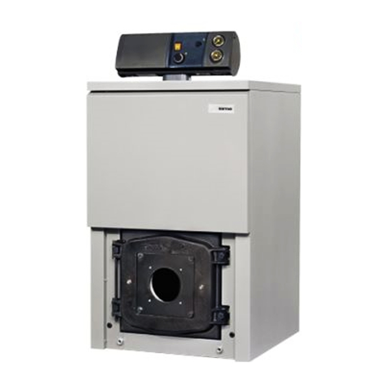
INTRODUCTION They use light oil and have a perfectly tions. balanced combustion with a very high The components for “1R - 2R free- The new “1R - 2R freestanding” thermal ef ficiency for economical standing” installation are supplied in series of cast iron boilers has been performance. -
Page 23: Loss Of Head
30÷85 30÷85 30÷85 30÷85 30÷85 30÷85 30÷85 Smoke volume Weight * Without baffles LOSS OF HEAD “1R” boiler 1R 9 1R 8 1R 7 1R 6 1R 5 1R 4 Flow m Portata m “2R” boiler 2R 15 2R 14... -
Page 24: Combustion Chamber Dimensions
COMBUSTION CHAMBER DIMENSIONS The dimensions of this direct passage combustion chamber are reported in fig. 3. The refractory brick is supplied on the “1R4” models. Fig. 3 A mm B mm L mm Volume m 0,025271 0,031891 0,038510 0,045129 0,051748 0,058367 2R10 2R11... -
Page 25: Installation
60° - 45° 1.6.4 Burner assembly The boiler is supplied to be assembled on the burner. The connection flange dimensions are indicated in fig. 4. ø 1R 4÷6 1R 7÷9 2R 6-7 Fig. 4 2R 8÷15 INSTALLATION 2. 1 BOILER ROOM to disconnect by means of tightening –... -
Page 26: Boiler Body Assembly
with a static exhaust device that force, bring the two pieces together ensures const ant and ef ficient so that they are parallel. extraction of products generated by The sections can be considered pro- combustion; perly joined together when their –... -
Page 27: Electrical Connection
NOTE: fuses. minals 4-5 after removing the link SIME declines all responsibility for The room thermostat (required for (fig. 9). Connect the burner cable injury caused to persons due to fai- enhanced room temperature con- supplied. -
Page 28: Use And Maintenance
The safety stat with automatic reset cleaned at the end of each season. authorised technical personnel in your calibration set at 100°C (2 fig. 1) trips, To clean the boiler, simply remove the area. “1R” boiler “2R” boiler Fig. 11... - Page 29 Dans le notice technique conserver le “Certificat d’essai” placé dans la cham- bre de combustion TABLE DES MATIERES DESCRIPTION DE LA CHAUDIERE 1. 1 INTRODUCTION ..................28 DIMENSIONS D’ENCOMBREMENT DONNEES TECHNIQUES PERTES DE CHARGE .
- Page 30 á l’entretien. Les groupes avec un très haut rendement qui per- thermiques "1R - 2R freestanding" sont Les chaudières en fonte “1R - 2R free- mettent de réaliser de très importantes livrés en trois colis séparés: corps de la standing”...
- Page 31 30÷85 30÷85 30÷85 30÷85 30÷85 30÷85 30÷85 Volume fumées Poids * Sans chicanes PERTES DE CHARGE Serie “1R” 1R 9 1R 8 1R 7 1R 6 1R 5 1R 4 Débit m Portata m Serie “2R” 2R 15 2R 14...
- Page 32 DIMENSIONS CHAMBRE DE COMBUSTION La chambre de combustion est à pas- sage direct. Ses dimensions sont reportées sur la fig. 3. La dalle réfractaire est fournie par les modèles “1R4”. Fig. 3 A mm B mm L mm Volume m 0,025271 0,031891 0,038510...
- Page 33 1.6.4 Montage du brûleur La chaudière livrée est prédisposée pour le montage du brûleur. Les dimensions de la bride de fixation sont indiquées sur la fig. 4. ø 1R 4÷6 1R 7÷9 2R 6-7 Fig. 4 2R 8÷15 INSTALLATION 2. 1...
- Page 34 de la chaudière; en effet si elle n’est ASSEMBLAGE DU pas exécut ée conformément aux CORPS DE CHAUFFE règles de l’art on pourrait avoir des démarrages difficiles avec conséquen- En standard, le corps est fourni monté: te formation de suie, condensation, en cas de difficulté...
- Page 35 MONTAGE DE LA JAQUETTE La jaquette et le panneau d'instru- ments sont fournis à part, dans des confections en carton. Dans le même emballage de la jaquette se trouve les documents de la chaudière et la laine de verre déjà prête pour isoler le corps de chauffe en fonte.
- Page 36 à 60°C. Pour contrôler la valeur de température programmée, consulter le thermomètre (4). Serie “1R” Serie “2R” 3.2.2 Aquastat de sécurité L’aquastat de sécurité à réarmement automatique étalonné à 100°C (2 fig.
- Page 37 Shranite s to knjiæico tudi “Potrdilo o odobritvi peËi”, ki je vneπeno v komori KAZALO OPIS PE»I UVOD ..............36 MERE TEHNI»NI PODATKI IZGUBE PRI NAPELJAVAH .
- Page 38 92/92. Delujejo na kurilno olje z delovanje in vzdræevanje. TermiËne uravnoteæenim izgorevanjem in z skupne “1R - 2R freestanding” so Nove peËi iz litega æeleza “1R - 2R visokim uËinkom, ki dovoljuje znaten razdeljene na tri dele: telo peËi, freestanding” so naËrtovane v prihranek pri uporabi.
- Page 39 30÷85 30÷85 30÷85 30÷85 30÷85 30÷85 30÷85 Volumen dima Teæa * Brez turbolatorjev IZGUBE PRI NAPELJAVAH Izvedba “1R” 1R 9 1R 8 1R 7 1R 6 1R 5 1R 4 Pretok m Portata m Izvedba “2R” 2R 15 2R 14...
- Page 40 MERE GORI©»A GoriπËe je tipa z direktnim preho- dom, njegove dimenzije so pred- stavljene na sliki 3. Samotno opeko dobavimo samo na modele “1R4”. Risba 3 A mm B mm L mm Volumen m 0,025271 0,031891 0,038510 0,045129 0,051748 0,058367 2R10 2R11 2R12...
- Page 41 60° - 45° 1.6.4 Montiranje gorilnika PeË je izdelana tako, da je mogoËe vgraditi gorilnik. Dimenzjie flanπe za pritrditev so oznaËene na sliki 4. ø 1R 4÷6 1R 7÷9 2R 6-7 Risba 4 2R 8÷15 INSTALACIJA KURILNICA navedena ob risbi πt. 1. Primerno polnjenja posode in pritisk polnjenja je, da so vsi prikljuËki povezani s...
- Page 42 Dimna cev mora torej odgovarjati peËi morate strogo slediti sledeËim zahtevam: naslednjim navodilom: – Mora biti iz nepropustnega – Pripravimo razne elemente, tako materiala ter mora biti odporna da πËistimo koniËne niples z raz- na visoke temperature in kon- topilom. denzacijo.
- Page 43 OPOMBA: instalacija je obvezna, da bomo ELEKTRI»NA dobili boljπo regulacijo temperatu- Podjetje SIME odklanja PRIKLJU»ITEV re v sobah, ga bomo morali pritr- kakrπnokoli odgovornost diti na spojke 4-5 potem ko smo poπkodbe oseb, do katerih bi PeË...
- Page 44 3.2.2 Varnostni termostat Varnostni termostat na avtomatsko vkljuËenje, ki je naravnan da 100°C (2 risba 10) se vkljuËi in sproæi Izvedba “1R” Izvedba “2R” avtomatsko ugasitev gorilnika v pri- meru, da v peËi po nesreËi pride do previsoke temperature. Za ponovno vkljuËitev peËi poËakajte, da se tem-...
- Page 45 Het “Testcertificaat” dat zich in de verbrandingskamer bevindt dient bij de documentatie van de verwarmingsketel te worden bewaard INHOUD BESCHRIJVING VAN DE KETEL 1. 1 INLEIDING ................... . 44 UITWENDIGE AFMETINGEN TECHNISCHE GEGEVENS DRUKVERLIES .
- Page 46 De “1R - 2R lanceerde verbranding en hebben een freestanding” ketels worden in drie De gietijzeren ketels “1R - 2R free- zeer hoog rendement dat een grote afzonderlijke verpakkingen afgeleverd: standing” zij in overeenstemming met brandstofbesparing toestaat.
- Page 47 30÷85 30÷85 30÷85 30÷85 30÷85 30÷85 30÷85 30÷85 Rookgasvolume Gewicht * Zonder turbulatoren DRUKVERLIES Ketel “1R” 1R 9 1R 8 1R 7 1R 6 1R 5 1R 4 Debiet m Portata m Ketel “2R” 2R 15 2R 14 2R 13...
- Page 48 WAND VAN DE VERBRANDINGSKAMER De verbrandingskamer is van het type met rechtstreekse doorlaat. De afme- tingen staan aangegeven op fig. 3. De hittebestendige steen wordt geleverd op de ketels “1R4”. Fig. 3 A mm B mm L mm Volume m 0,025271 0,031891 0,038510...
- Page 49 1.6.4 Montage van de brander De ketel wordt gereed voor de monta- ge van de brander geleverd. De afmetingen van de bevestiging- sflens zijn aangegeven in fig. 4. ø 1R 4÷6 1R 7÷9 2R 6-7 Fig. 4 2R 8÷15 INSTALLATIE 2.
- Page 50 het starten van de ketel problemen, MONTAGE VAN HET zoals vorming van roet, condensatie, KETELLICHAAM afzettingen opleveren. De schoorsteen moet beantwoorden Het ketellichaam wordt standaard geas- aan de onderstaande vereisten. sembleerd afgeleverd; indien er proble- Hij dient in het bijzonder: men zijn bij het installeren in de verbran- –...
- Page 51 MONTAGE VAN DE MANTEL De mantel en het instrumentenbord worden in aparte kartonnen verpakkin- gen afgeleverd. In de verpakking van de mantel bevindt zich het zakje met de documentatie van de verwarming- sketel en de reeds geprepareerde gla- swol om het gietijzeren verwarmingsli- chaam te isoleren.
- Page 52 Erkende Technische Servicedienst in ter (4) worden gecontroleerd. Voordat u de modellen “1R4 ÷ 1R6” uw regio wenden. 3.2.2 Veiligheidsaquastaat Serie “1R” Serie “2R” De veiligheidsaquastaat met automati- sche reset die op 100 °C is ingeregeld (2 fig. 10) schakelt in waardoor de...
- Page 53 AÊ·ÈÚ¤ÛÙ ÙÔ “¶ÈÛÙÔ ÔÈËÙÈÎfi ‰ÔÎÈÌ‹˜” · fi ÙÔÓ ı¿Ï·ÌÔ Î·‡Û˘ Î·È Ê˘Ï¿ÍÙ ÙÔ Ì ÙÔ ÂÁ¯ÂÈÚ›‰ÈÔ Ô‰ËÁÈÒÓ. ¶INAKA™ ¶EPIEXOMENøN ¶EPI°PAºH §EBHTA EI™A°ø°H ............... . 52 ¢IA™TA™EI™...
- Page 54 Ù¤ÏÂÈ· ÈÛÔÚÚÔ Ë̤ÓË Î·‡ÛË Ì T·  È̤ÚÔ˘˜ ÙÌ‹Ì·Ù· ÙÔ˘ Ϥ‚ËÙ· ı¤ÚÌ·ÓÛ˘ “1R - 2R freestanding” ÌÂÁ¿ÏË ıÂÚÌÈ΋ · fi‰ÔÛË ÁÈ· “1R - 2R freestanding” Û ÙÚ›· ÌÂÏÂÙ‹ıËÎ·Ó Î·È Î·Ù·Û΢¿˙ÔÓÙ·È ÔÈÎÔÓÔÌÈ΋ ÏÂÈÙÔ˘ÚÁ›·. ͯˆÚÈÛÙ¿ ÎfiÏ·: ÛÒÌ· Ϥ‚ËÙ·, Û‡Ìʈӷ Ì ÙËÓ Ô‰ËÁ›· ÁÈ· ÙȘ...
- Page 55 30÷85 30÷85 30÷85 30÷85 30÷85 30÷85 30÷85 ŸÁÎÔ˜ ¯ÒÚÔ˘ η˘Û·ÂÚ›ˆÓ µ¿ÚÔ˜ * .¯ˆÚ›˜ ÛÙÚÔ‚ÈÏÈÛÙ¤˜ η˘Û·ÂÚ›ˆÓ ¶Tø™H ¶IE™H™ NEPOY §¤‚ËÙ·˜ “1R” 1R 9 1R 8 1R 7 1R 6 1R 5 1R 4 ¶·ÚÔ¯‹ mÑ/h §¤‚ËÙ·˜ “2R” 2R 15 2R 14...
- Page 56 ¢IA™TA™EI™ £A§AMOY KAY™H™ O ı¿Ï·ÌÔ˜ Â›Ó·È Ù‡ Ô˘ ¿ÌÂÛ˘ ‰È·‰ÚÔÌ‹˜. OÈ ‰È·ÛÙ¿ÛÂȘ Ê·›ÓÔÓÙ·È ÛÙËÓ ÂÈÎ. 3. ∆Ô ˘Ú›Ì·¯Ô ÙÔ‡‚ÏÔ ·Ú¤¯ÂÙ·È ÌfiÓÔ Ì ÙÔ˘˜ Ϥ‚ËÙ˜ “1R4”. ∂ÈÎ. 3 A ¯ÈÏ. B ¯ÈÏ. L ¯ÈÏ. ŸÁÎÔ˜ m 0,025271 0,031891 0,038510 0,045129 0,051748 0,058367 2R10 2R11...
- Page 57 1.6.4 ™˘Ó·ÚÌÔÏfiÁËÛË Î·˘ÛÙ‹Ú· O Ϥ‚ËÙ·˜ ·Ú·‰›‰ÂÙ·È ¤ÙÔÈÌÔ˜ ÁÈ· ÙËÓ ÙÔ Ôı¤ÙËÛË ÙÔ˘ η˘ÛÙ‹Ú·. OÈ ‰È·ÛÙ¿ÛÂȘ Ù˘ ÊÏ¿ÓÙ˙·˜ ÙÔ Ôı¤ÙËÛ˘ Ê·›ÓÔÓÙ·È ÛÙËÓ ÂÈÎ. 4. ¯ÈÏ. ¯ÈÏ. ø 1R 4÷6 1R 7÷9 2R 6-7 ∂ÈÎ. 4 2R 8÷15 °ENIKE™ A¶AITH™EI™ E°KATA™TA™H™ §EBHTO™TA™IO ™YN¢E™H §EBHTA (ÌÂ...
- Page 58 ÙfiÙÂ Ë ÂÎΛÓËÛË ÙÔ˘ Ϥ‚ËÙ· ı· ™øMA §EBHTA Î·È Î·ÙÒÙÂÚÔ ÙÌ‹Ì· Â›Ó·È ‰‡ÛÎÔÏË Î·È Ì ÔÚ› Ó· Ù·˘ÙÔ¯ÚfiÓˆ˜. ‰ËÌÈÔ˘ÚÁ› ·Èı¿ÏË, Û˘Ì ˘ÎÓÒÌ·Ù· TÔ ÛÒÌ· ÙÔ˘ ·Ú·‰›‰ÂÙ·È E¿Ó ηٿ ÙËÓ ‰È¿ÚÎÂÈ· ·˘Ù‹˜ Î·È ÎÚÔ‡ÛÙ·. η Ó·ÁˆÁfi˜ Û˘Ó·ÚÌÔÏÔÁË̤ÓÔ. Ÿ Ô˘ ˘ ¿Ú¯ÂÈ Ù˘...
- Page 59 ÛÙÔ TS £ÂÚÌÔÛÙ¿Ù˘ ·ÛÊ·Ï›·˜ ˘ ¿Ú¯ÔÓ Î·ÏÒ‰ÈÔ. K·˘ÛÙ‹Ú·˜ (‰ÂÓ ·Ú¤¯ÂÙ·È) SB §˘¯Ó›· ‚Ï¿‚˘ η˘ÛÙ‹Ú· ™HMEIø™H: H SIME · Ô ÔÈÂ›Ù·È ™HMEIø™H: O ıÂÚÌÔÛÙ¿Ù˘ ¯ÒÚÔ˘ Û˘Ó‰¤ÂÙ·È Î¿ı ¢ı‡Ó˘ ˙ËÌÈÒÓ Û ˘ÏÈο ‹ ÛÙȘ ÎϤ̘ 4-5, ·ÊÔ‡ ·Ê·ÈÚÂı› Ë Á¤Ê˘Ú·. ¿ÙÔÌ· ÛÂ...
- Page 60 ÚfiÛ‚·Û˘ ÛÙÔ˘˜ ÙÚÂȘ ·ÚÈÔ˘˜ ˘ ÔÛÙ‹ÚÈ͢ Ù˘ ÂÚÈÔ¯‹˜. · ÔÊ˘Á‹ Û˘Ì ˘Îӈ̿وÓ. ∏ ıÂÚÌÔÎÚ·Û›· ÙÔ˘ Ϥ‚ËÙ· Ê·›ÓÂÙ·È ÛÙÔ ıÂÚÌfiÌÂÙÚÔ (4). §¤‚ËÙ·˜ “1R” §¤‚ËÙ·˜ “2R” 3.2.2 £ÂÚÌÔÛÙ¿Ù˘ ·ÛÊ·Ï›·˜ O ıÂÚÌÔÛÙ¿Ù˘ ·ÛÊ·Ï›·˜ (2 ÂÈÎ. 10) Â›Ó·È ÙÔ˘ Ù‡ Ô˘ ·˘ÙfiÌ·Ù˘  ·Ó·ÊÔÚ¿˜...
- Page 61 Direttiva rendimenti 92/42 CEE Legnago, 1 luglio 1998 FONDERIE SIME SpA il Direttore Generale ing. ALDO GAVA Fonderie Sime S.p.A. - Via Garbo, 27 - 37045 Legnago (Vr) - Tel. 0442 631111 - Fax Servizio Tecnico 0442 631292 - www.sime.it...
- Page 64 Fonderie Sime S.p.A. - via Garbo, 27 - 37045 Legnago (Vr) Tel. 0442 631111 - Fax Serv. Commerciale Italia 0442 631291 - Fax Serv. Tecnico 0442 631292 Tel. +39/0442 631111 - Export Division fax number +39/0442 631293 - Sime Service fax number +39/0442 631292...
Need help?
Do you have a question about the 1R and is the answer not in the manual?
Questions and answers