Fronius Primo GEN24 208-240 Operating Instructions Manual
Hide thumbs
Also See for Primo GEN24 208-240:
- User manual ,
- Operating instructions manual (112 pages) ,
- Application manual (27 pages)

Subscribe to Our Youtube Channel
Related Manuals for Fronius Primo GEN24 208-240


Summary of Contents for Fronius Primo GEN24 208-240
- Page 1 Operating Instructions Fronius Primo GEN24 208-240 7.7 / 10.0 EN-US Operating instructions 42,0426,0312,EA 009-25042024...
-
Page 3: Table Of Contents
Safety General Environmental conditions Qualified personnel Data on noise emission values EMC measures Backup power Equipment grounding (GND) General information Fronius Primo GEN24 Device concept Function overview Scope of supply Intended use Thermal concept Data backup Fronius Solar.web Local communication Different operating modes Operating modes –... - Page 4 Preparing knockouts for connection Installing the mounting bracket and attaching the inverter Selecting the mounting material Properties of the mounting bracket Do not deform the mounting bracket Fitting the mounting bracket to a wall Installing the mounting bracket on a mast or beam Attaching the mounting bracket to mounting rails Attaching the inverter to the mounting bracket Requirements for connecting the inverter...
- Page 5 Fronius manufacturer's warranty Status codes and remedy Display Status codes Technical data Technical data for Fronius Primo GEN24 7.7 208 - 240 Technical data for Fronius Primo GEN24 10.0 208 - 240 WLAN Explanation of footnotes Integrated DC disconnector Circuit Diagrams Emergency power terminal—PV Point (OP)
-
Page 6: Safety Rules
Safety rules Explanation of WARNING! safety instruc- tions Indicates a potentially dangerous situation. ▶ Death or serious injury may result if appropriate precautions are not taken. CAUTION! Indicates a potentially harmful situation. ▶ Minor injury or damage to property may result if appropriate precautions are not taken. -
Page 7: Environmental Conditions
All installations must comply with national and local electrical codes and stand- ards. In addition to the Operating Instructions, all applicable local regulations regard- ing accident prevention and environmental protection must also be followed. All safety and danger notices on the device: Must be kept in a legible state Must not be damaged Must not be removed... -
Page 8: Emc Measures
The cooling of the device takes place via an electronic temperature control sys- tem at the lowest possible noise level and depends on the power used, ambient temperature, and the soiling level of the device, etc. It is not possible to provide a workplace-related emission value for this device, because the actual sound pressure level is heavily influenced by the installation situation, the power quality, the surrounding walls, and the properties of the room in general. -
Page 9: Equipment Grounding (Gnd)
IMPORTANT! Very high start-up currents can temporarily distort or interrupt the output voltage. Simultaneous operation of electronic devices in the same backup power grid should be avoided. IMPORTANT! The inverter may only be operated within the limits of its technical capabilities. Operation outside of its technical capabilities can cause the inverter to shut down. -
Page 11: General Information
General information... -
Page 13: Fronius Primo Gen24
Fronius provides the application Solar.cre- ator, available at https://creator.fronius.com/. The Fronius repowering tool (https://repowering.fronius.com/) supports in- stallers and Fronius System Partners with repowering existing photovoltaic sys- tems. The inverter has backup power functions and switches to backup power mode if it has been wired accordingly*. -
Page 14: Scope Of Supply
Follow all grid operator regulations regarding grid power feed and connection methods. The Fronius GEN24 inverter is a grid-connected inverter with backup power func- tion and is not a stand-alone inverter. The following restrictions in backup power mode must therefore be observed: The inverter may be operated for max. -
Page 15: Thermal Concept
These specifications do not provide an absolute guarantee of flawless op- eration. High error rates in the transmission, fluctuating receptions or mis- fires can have an adverse effect on data transfer. Fronius recommends on- site testing to ensure that the connections meet the minimum require-... -
Page 16: Local Communication
Local commu- The inverter can be found via the Multicast DNS (mDNS) protocol. We recom- nication mend searching for the inverter using the assigned host name. The following data can be called up via mDNS: NominalPower Systemname DeviceSerialNumber SoftwareBundleVersion... -
Page 17: Different Operating Modes
Primary meter records the load curve of the system and makes the measured data available for energy profiling in Fronius Solar.web. The primary meter also regulates the dynamic feed-in control. Secondary meter records the load curve of individual loads (e.g., washing machine,... -
Page 18: Operating Mode - Inverter With Smart Meter
Operating mode - Inverter with Smart Meter 0 0 1 max. 3.1 kW Operating mode – Inverter with several Smart 0 0 1 Meters 0 0 1 max. 3.1 kW... -
Page 19: Protection Of People And Equipment
Protection of people and equipment Rapid shutdown Two different types of rapid shutdown (RSD) can be triggered depending on the configuration and on-site installation: Via external buttons: One or more external buttons can be installed on the WSD (wired shutdown) interface of the Data communication area on page 25. -
Page 20: Power Line Communication (Plc) Transmitter
In case a string-level shutdown equipment at the PV array is used in combination with the inverter, this labeling has to be used acording to NEC (Section 690.12), CEC (Section 64-218): SOLAR PV SYSTEM EQUIPPED WITH RAPID SHUTDOWN SOLAR PV SYSTEM IS EQUIPPED WITH RAPID SHUTDOWN. -
Page 21: Additional External Ac And/Or Dc Disconnect
To ensure compliance with all applicable regulations in your country and to en- sure optimal reception among all recipients, please follow the recommendations below: Keep the distance between the DC+ and DC- conductors as small as possible Avoid cable loops caused by cables that are too long (coil effect) Use metal cable ducts where possible Do not place DC cables from different inverters in the same cable duct or cable tray... -
Page 22: Standby State
IMPORTANT! Fronius will not bear any costs for production downtimes, installation costs, etc., which may arise due to a detected electric arc and its consequences. Fronius ac- cepts no liability for damage which may occur despite the integrated Arc Fault Circuit Interrupter/interruption (e.g., due to a parallel arc). -
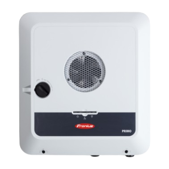
Page 23: Operating Controls And Connections
Operating controls and connections Connection area 2 x 5-pin DC push-in terminal Push-in WSD (wired shutdown) terminal Push-in terminals in the data communication area (Modbus, digital inputs and outputs) 3-pin push-in terminal for PV Point (OP) 4-pin AC push-in terminal 6-pin ground electrode terminal... -
Page 24: Connection Area Divider
Connection area divider AC conduit connection (Ø ½ - 1 inch / 13 - 25 mm) Ground spike conduit connection (Ø 5/8 inch / 16 mm) (10) DatCom conduit connection (Ø ½ - ¾ inch / 13 - 19 mm) (11) Data communication area conduit connection (12) -
Page 25: Dc Disconnector
DC disconnector The DC disconnector has three switch settings: Locked/off (turned to the left) IMPORTANT! In switch settings (1) and (3), the in- verter can be secured to prevent it from being switched on/off using a standard padlock. The national guidelines must be complied with in this respect. -
Page 26: Button Functions And Led Status Indicator
LED status shown via the operating status indicator LED. In the event of faults, carry out the individual steps in the Fronius Solar.start app. The optical sensor is actuated WLAN access point by touching with a finger. 3-6 sec. - Page 27 Sensor functions = WLAN Access Point (AP) is opened. Flashing blue = WLAN Protected Setup (WPS) is activated. Flashing green 3 seconds (max. 6 seconds) = the service message is acknowledged. Flashing white (rapidly) LED status indicator The inverter is operating correctly. Lights up green The inverter is performing the grid checks required by the applicable standards for feed-in mode.
-
Page 28: Schematic Internal Wiring Of Ios
LED status indicator The inverter is operating correctly, a network fault is in- dicated. Lights up red The network connection is active. Lights up blue The inverter is performing an update. Flashing blue There is a service message. Lights up white Schematic in- The V+/GND pin provides the possibility of feeding in a voltage in the range of ternal wiring of... -
Page 29: Backup Power Variant - Pv Point (Op)
Backup power variant - PV Point (OP) -
Page 31: General
General PV Point (OP) WARNING! Limited rapid shutdown function in backup power mode (PV Point and Full Backup) If PV Point or Full Backup is con- figured, rapid shutdown cannot be triggered via the loss of grid connec- tion. This can result in serious personal injury and damage to the PV system. - Page 32 If no energy from the PV modules is available in backup power mode, backup power mode ends automatically. Backup power mode restarts again automatic- ally once sufficient energy can once again be provided by the PV modules. In the event of excessive loads, backup power mode is stopped and the "Backup power overload"...
-
Page 33: Installation
Installation... -
Page 35: General
General Quick-fastener A quick-fastener system (3) is used to system mount the connection area cover and front cover. The system is opened and closed with a half-rotation (180°) of the captive screw (1) into the quick- fastener spring (2). The system is independent of torque. NOTE! Danger when using a drill driver. - Page 36 This device complies with Part 15 of the FCC Rules. Operation is sub- ject to the following conditions: This device must not cause any harmful interference. This device must not be affected by external sources of interfer- ence, including interference that may impair operation. Safety symbols: Danger of serious injury and property damage due to incorrect opera- tion...
-
Page 37: Installation Location And Position
For more detailed information on in- verter dimensions, refer to the chapter headed Fronius Primo GEN24 7.7 - 10.0 208-240 on page 119. When installing the inverter on the outer walls of cattle sheds, it is important to maintain a minimum clearance of 6.5 ft between all sides of the inverter and... - Page 38 The inverter is suitable for outdoor installation. Type 4X When properly installed, the inverter has a Type 4X protection class, is not susceptible to spraying water on any side and can also be operated in moist environments. In order to keep inverter heating as low as possible, do not ex- pose the inverter to direct sunlight.
-
Page 39: Installation Position Of The Inverter
Installation posi- The inverter is suitable for vertical installation on a vertical wall tion of the in- or column. verter The inverter is suitable for installation on a sloping surface (min. slope of underside 10°). Do not install the inverter on a sloping surface with the connec- tions upwards. - Page 40 Do not install the inverter on the ceiling.
-
Page 41: Knockouts
Knockouts Preparing IMPORTANT! The knockouts must be drilled out using a step drill bit only. The knockouts for maximum conduit sizes are ½ - 1 inch / 13 - 25 mm. connection IMPORTANT! Void warranty if the conduit holes are drilled improperly. Use suitable eye protection when drilling out the knockouts. -
Page 42: Installing The Mounting Bracket And Attaching The Inverter
Installing the mounting bracket and attaching the inverter Selecting the Use the corresponding fixing materials depending on the subsurface and observe mounting mater- the screw dimension recommendations for the mounting bracket. The installer is responsible for selecting the right type of fixing. Properties of the The mounting bracket (illustration) can mounting brack-... -
Page 43: Installing The Mounting Bracket On A Mast Or Beam
Installing the When installing the inverter on a mast mounting brack- or beam, Fronius recommends using et on a mast or the "Pole clamp" (order no. SZ beam 2584.000) mounting kit from Rittal GmbH. The "Pole clamp" kit covers the follow-... -
Page 44: Attaching The Mounting Bracket To Mounting Rails
Attaching the IMPORTANT! mounting brack- The mounting bracket must be affixed et to mounting at a minimum of four points. rails Attaching the in- Integrated grips, which facilitate lift- verter to the ing/clipping, are located on the side of mounting brack- the inverter. -
Page 45: Requirements For Connecting The Inverter
Requirements for connecting the inverter Various cable Fine-stran- Fine-stran- types ded with fer- ded with fer- rule and col- rule without Multi-stran- Fine-stran- Solid collar Permitted cables "Round copper conductors can be connected to the terminals of the inverter as for the electrical described below": connection... -
Page 46: Cable Diameter For Push-In Terminals
Ground electrode terminal (6-pin) Select a sufficiently large cable cross-section based on the actual device output. AWG 14–6 / AWG 14–6 / AWG 14–6 / AWG 14–6 / AWG 14–6 / 2.5 - 16 mm² 2.5 - 16 mm² 2.5 - 16 mm² 2.5 - 16 mm²... -
Page 47: Maximum Alternating Current Fuse Protection
AWG 26–16 ductors 29 m possible LAN connections Fronius recommends using at least CAT 5 STP (shielded twisted pair) cables and a maximum dis- tance of 109 yd / 100 m. Maximum altern- NOTE! ating current The national regulations of the grid... - Page 48 Recommended Maximum fuse rating ( 208V / Inverter Phases fuse rating 220V / 240 V) Fronius Primo GEN24 10.0 65 A 60 A / 60 A / 55 A 208-240...
-
Page 49: Connecting The Inverter To The Public Grid (Ac Side)
Connecting the inverter to the public grid (AC side) Safety WARNING! Danger from incorrect operation and work that is not carried out properly. This can result in severe personal injury and damage to property. ▶ Read the Installation Instructions and Operating Instructions before in- stalling and commissioning the equipment. -
Page 50: Connecting The Inverter To The Public Grid (Ac Side)
208 V Delta Corner Grounded 220 V Delta Corner Grounded 240 V Delta Corner Grounded 208 V 220 V 240 V Connecting the NOTE! inverter to the public grid (AC In grid configurations with neutral conductors, the neutral conductor must be side) connected in order to operate the inverter. - Page 51 Loosen the five screws of the connec- tion area cover by rotating them 180° to the left using a screwdriver (TX20). Remove the connection area cover from the device. Guide the mains cable from below through the electrical installation tube on the right side.
- Page 52 Phase conductor Nsens Neutral conductor* Phase conductor * Valid for grid configurations with neutral conductors. Fasten the grounding cable to the ground electrode terminal using a screwdriver (TX20) and a torque of 1.475 ft lbs / 2 Nm. Insert the AC terminal into the AC slot until it engages.
-
Page 53: Connecting Solar Module Strings To The Inverter
This can result in severe personal injury and damage to property. ▶ The commissioning, maintenance, and service work in the inverter's power stage set may only be carried out by Fronius-trained service personnel in ac- cordance with the technical specifications. ▶... -
Page 54: Pv Generator, General
WARNING! Danger from grid voltage and DC voltage from PV modules that are exposed to light. This can result in severe personal injury and damage to property. ▶ All connection, maintenance, and service work should only be carried out when the AC and DC sides have been disconnected from the inverter and are de-energized. -
Page 55: Connecting Solar Module Strings To The Inverter
Module array settings: PV 1: ON PV 2: ON PV 1 less than or equal to 41.25 A (I SC PV1 ) PV 2 less than or equal to 36 A (I SC PV2 ) Connecting solar module strings to the inverter... - Page 56 Guide the DC cables through the elec- trical installation tube. IMPORTANT! Guide the cables through the electrical installation tube before stripping them in order to avoid twisting/bending single wires.
- Page 57 Select the cable cross-section in ac- cordance with the instructions in Per- mitted cables for the electrical con- nection from page 45. Strip the insulation of the single con- ductors by 0.47 inches. Lift to open the terminal's operating lever and in- sert the stripped single conductor into the slot provided in the terminal as far as it will go.
- Page 58 Use a suitable measuring instrument to check the voltage and polarity of the DC cabling. Remove both DC ter- minals from the slots. CAUTION! Danger due to polarity reversal at the terminals. This may result in severe damage to the inverter. ▶...
-
Page 59: Connecting Backup Power - Pv Point (Op)
Connecting backup power - PV Point (OP) Safety WARNING! Danger from incorrect installation, commissioning, operation or incorrect use. This can result in severe personal injury and damage to property. ▶ Single 120 / 220 / 240 volt supply. Do not connect multi-wire branch circuits! ▶... -
Page 60: Installation
In order to ensure the ground fault circuit interrupter operates properly, a con- nection must be established between the neutral conductor N' (OP) and equip- ment grounding (GND). Wiring proposal recommended by Fronius, see page 115. Turn off the automatic circuit breaker. Set the DC disconnector to the "Off"... - Page 61 Drill out the knockout with a step drill. Insert the conduit into the knockout and fasten it using the torque specified Preparing by the manufacturer. Seal the conduit as per the chapter headed knockouts for connection on page 41. Guide the mains cable through the conduit from below.
- Page 62 L1´ Phase conductor N´ Neutral conductor N´ Ground conductor NOTE! The ground conductor must be pro- duced with ends that are permanently marked blue, according to the national provisions, and have a cross-section of AWG 6. Fasten the ground conductor and PEN conductor to the ground electrode ter- minal using a screwdriver (TX20) and a torque of 1.47 ft-lbs / 2 Nm.
-
Page 63: Connecting The Data Communication Cables
Connecting the data communication cables Modbus parti- The inputs M0 and M1 can be freely selected. A maximum of four Modbus parti- cipants cipants can be connected to the Modbus terminal at inputs M0 and M1. IMPORTANT! Only one primary meter can be connected to each inverter. If the "Inverter Con- trol via Modbus"... -
Page 64: Routing Data Communication Cables
Routing data Drill out the knockout with a step drill. communication cables Insert the conduit into the hole and fasten it using the torque specified by the manufacturer. Seal the conduit as per the chapter headed Preparing knockouts for connection on page 41. - Page 65 OPTION 1 Modbus 1 Modbus 0 Manufacturer manual Manufacturer manual 0 0 1 Modbus 0 / 1 Modbus 0 / 1 (min. CAT 5) (min. CAT 5) OPTION 2 M0 / M1 Manufacturer manual Manufacturer manual 0 0 1 Modbus 0 / 1 Modbus 0 / 1 (min.
-
Page 66: Installing The Wsd (Wired Shutdown)
Installing the WARNING! WSD (wired shutdown) Limited rapid shutdown function in backup power mode (PV Point and Full Backup) If PV Point or Full Backup is con- figured, rapid shutdown cannot be triggered via the loss of grid connec- tion. This can result in serious personal injury and damage to the PV system. -
Page 67: Closing And Commissioning The Inverter
Closing and commissioning the inverter Closing the in- NOTE! verter's connec- tion area/hous- The housing cover is fitted with a lock for safety reasons, which allows the hous- ing cover on the inverter to be pivoted only when the DC disconnector is off. ing cover, and ▶... -
Page 68: Installation With The App
Installation with The "Fronius Solar.start" app is required for installation. Depending on the mo- the app bile device used to perform the installation, the app is available on the relevant platform. Fronius Solar.start open access point Download and install the Fronius Solar.start app. - Page 69 The network wizard and product setup can be performed independently. A net- work connection is required for the Solar.web installation wizard. Ethernet: 192.168.250.180 open access point Establish a connection to the inverter (LAN1) using a network cable (min. CAT5 STP). Open the access point by touching the sensor once Communications LED flashes blue.
-
Page 70: Energizing The Inverter And Switching It Back On
De-energizing the inverter and switching it back De-energizing Turn off the automatic circuit the inverter and breaker. switching it back Turn the DC disconnector to the "Off" switch setting. To start up the inverter again, follow the steps listed above in reverse order. -
Page 71: Settings - User Interface Of The Inverter
Settings – User interface of the in- verter... -
Page 73: User Settings
User settings User login Open the user interface of the inverter in the browser. In the menu field "Log In", log in with username and password, or, in the menu field "User", click on the "User login" button and log in with username and password. -
Page 74: Device Configuration
Primary meter For problem-free operation with further energy generators and in Full Backup power operation, it is important to install the Fronius Smart Meter at the feed-in- point. The inverter and further producers must be connected to the public grid via the Fronius Smart Meter. - Page 75 A residual current circuit breaker in individual cases and depending on local conditions. For this reason, Fronius recommends using a residual current circuit breaker suitable for fre- quency inverters with a release current of least 100 mA, taking into account na-...
- Page 76 Parameter Value range Description "Inverter shut- No measures to prevent false alarms. down before 30 The inverter shuts down at 15 mA, before mA FI triggers" the residual current circuit breaker is triggered. "Leakage cur- 0 ‑ 0.25 By reducing the set value, the leakage cur- rent factor for (default: 0.16) rent is reduced and the intermediate cir-...
- Page 77 Parameter Value range Description "Backup power 0 ‑ 600 s Waiting time for restarting backup power restart delay" mode following a shutdown. "Backup power 1 ‑ 10 The max. number of automated restart at- restart at- tempts. Once the max. number of auto- tempts"...
-
Page 78: Load Management
Load management Load manage- "Rules" ment It is possible for up to four different load management rules to be defined. At the same threshold values, the rules are activated in succession. For deactiva- tion, this is done in reverse; the I/O last switched on is the first to be switched off. -
Page 79: System
Click "Save". Update All available updates are provided on the product page and in the "Download Search" area at www.fronius.com Updating the firmware Drag the firmware file into the "drop file here" field, or select via "Select file". Update is started. -
Page 80: License Manager
Select the information individually by ticking the check boxes beside the in- formation or by ticking "Select all". Enter the file name into the input field and click the "Save" button. The PDF is created and shown. License manager The power data and functional scope of the inverter are stored in the license file. If the inverter, power stage set or data communication area is replaced, the li- cense file must also be replaced. - Page 81 The support user is activated. IMPORTANT! The support user exclusively enables Fronius Technical Support to configure set- tings on the inverter via a secure connection. Access is deactivated by clicking "End support user access" button. Creating support info (for Fronius Support team) "Create support info"...
-
Page 82: Communication
If a firewall is used for outgoing connections, the following protocols, server ad- dresses and ports must be allowed for successful data transfer: Tcp fronius-se-iot.azure-devices.net:8883 Tcp fronius-se-iot-telemetry.azure-devices.net:8883 Tcp fronius-se-iot-telemetry.azure-devices.net:443 Udp sera-gen24.fronius.com:1194 (213.33.117.120:1194) Tcp cure-se.fronius.com:443 Tcp firmware-download.fronius.com:443 Tcp froniusseiot.blob.core.windows.net:443 Tcp provisioning.solarweb.com:443 Upd/Tcp 0.time.fronius.com:123... -
Page 83: Modbus
For connection type "automatic" - enter WLAN password and host name. For connection type "static" - enter IP address, subnet mask, DNS and gate- way. "Connect" Click on the button. The connection is established. After connecting, the status of the connection services"... -
Page 84: Remote Control
"Modbus port" Number of the TCP port that is to be used for Modbus communication. "SunSpec Model Type" Depending on the SunSpec model, there are two different settings. float: SunSpec Inverter Model 111, 112, 113 or 211, 212, 213 or 701, 702, 703, 704, 705, 706, 707, 708, 709, 710, 711, 712, 713 int + SF: SunSpec Inverter Model 101, 102, 103 or 201, 202, 203 or 701, 702, 703, 704, 705, 706, 707, 708, 709, 710, 711, 712, 713... -
Page 85: Fronius Solar Api
Fronius Solar The Fronius Solar API is an IP-based, open JSON interface. If it is activated, IOT devices in the local network can access inverter information without authentica- tion. For security reasons, the interface is deactivated ex works and must be ac- tivated if it is required for a third-party application (e.g., EV charger, Smart Home... -
Page 86: Safety And Grid Requirements
The "Country Setup" menu area is intended exclusively for installers/service verter codes in technicians from authorised specialist companies. The inverter access code re- Solar.SOS quired for this menu area can be requested in the Fronius Solar.SOS portal. Requesting inverter codes in Solar.SOS: Go to solar-sos.fronius.com... -
Page 87: Feed-In Limit
The feed-in limit takes account of self-consumption in the household before the power of an inverter is reduced: An individual limit can be set. A Fronius Smart Meter can be connected to the Modbus push-in terminal of the data communication area, at the terminals M0/M1- / M0/M1+ for Mod- bus data. -
Page 88: Connection Diagram - 4 Relays
Example: Feed-in limit (not taking into account the efficiency) PV system to Fronius inverter: 5000 W Consumption in home: 1000 W Maximum permitted power of feeding in of the entire 60% = 3000 W system: In this example, only 3000 W may be fed into the grid at the grid feed-in point. - Page 89 100 % 60 % 30 % IN10 IN11 Ripple control signal receiver with 4 relays for effective power limitation. I/Os of the data communication area. Use pre-configured file for 4-relay operation: Download the file (.fpc) under 4-relay operation to the mobile device. Upload the file (.fpc) in the "I/O power management"...
-
Page 90: I/O Power Management
I/O power man- I/O Power Management agement set- V+/GND tings - 4 relays None None None None None DNO Feedback None not used None None DNO Rules IO control IO control Rule 1 IO control IO control Active Power Power Factor (cos φ) DNO Feedback Rule 2 Active Power... -
Page 91: Connection Diagram - 3 Relays
Connection dia- The ripple control signal receiver and the I/O terminal of the inverter can be con- gram - 3 relays nected to one another as shown in the connection diagram. For distances of over 11 yd between the inverter and the ripple control signal re- ceiver, a CAT 5 cable is recommended as a minimum and the shielding must be connected on one side at the push-in terminal of the data communication area (SHIELD). -
Page 92: I/O Power Management Settings - 3 Relays
I/O power man- I/O Power Management agement set- V+/GND tings - 3 relays None None None None None DNO Feedback None not used None None DNO Rules IO control IO control Rule 1 IO control None Active Power Power Factor (cos φ) DNO Feedback Rule 2 Active Power... -
Page 93: Connection Diagram - 2 Relays
Connection dia- The ripple control signal receiver and the I/O terminal of the inverter can be con- gram - 2 relays nected to one another as shown in the connection diagram. For distances of over 11 yd between the inverter and the ripple control signal re- ceiver, a CAT 5 cable is recommended as a minimum and the shielding must be connected on one side at the push-in terminal of the data communication area (SHIELD). -
Page 94: I/O Power Management Settings - 2 Relays
I/O power man- I/O Power Management agement set- V+/GND tings - 2 relays None None None None None DNO Feedback None not used None None DNO Rules IO control IO control Rule 1 None None Active Power Power Factor (cos φ) DNO Feedback Rule 2 Active Power... -
Page 95: Connection Diagram - 1 Relay
Connection dia- The ripple control signal receiver and the I/O terminal of the inverter can be con- gram - 1 relay nected to one another as shown in the connection diagram. For distances of over 10 m between the inverter and the ripple control signal re- ceiver, a CAT 5 cable is recommended as a minimum and the shielding must be connected on one side at the push-in terminal of the data communication area (SHIELD). -
Page 96: I/O Power Management Settings - 1 Relay
I/O power man- I/O Power Management agement set- V+/GND tings - 1 relay None None None None None DNO Feedback None not used None None DNO Rules IO control None Rule 1 None None Active Power Power Factor (cos φ) DNO Feedback Rule 2 Active Power... -
Page 97: Appendix
Appendix... -
Page 99: Service, Maintenance And Disposal
Copyright Copyright of these Operating Instructions remains with the manufacturer. Text and illustrations were accurate at the time of printing. Fronius reserves the right to make changes. The contents of the Operating Instructions shall not provide the basis for any claims whatsoever on the part of the purchaser. If you... -
Page 100: Operation In Dusty Environments
Operation in NOTE! dusty environ- If the inverter is operated in dusty environments, dirt may build up on the heat ments sink and fan. This may result in a loss of power due to insufficient cooling of the inverter. ▶ Make sure that the ambient air can always flow through the inverter's ventila- tion slots unimpeded. -
Page 101: Disposal
To start up the inverter again, follow the steps listed above in reverse order. Disposal Waste electrical and electronic equipment must be collected separately and re- cycled in an environmentally sound manner in accordance with the European Dir- ective and national law. Used equipment must be returned to the distributor or through a local authorized collection and disposal system. -
Page 102: Warranty Provisions
Fronius manu- Detailed warranty conditions specific to your country can be found online: facturer's war- tps://www.fronius.com/en/solar-energy/installers-partners/service-support/ ranty warranty-models To take advantage of the full warranty duration for your newly installed Fronius inverter or storage system, register your product at: www.solarweb.com... -
Page 103: Status Codes And Remedy
This can result in severe personal injury and damage to property. ▶ The installation and connection of an SPD surge protection device may only be carried out by Fronius-trained service personnel in accordance with the technical specifications. ▶ Observe safety rules. -
Page 104: Technical Data
Technical data Technical data DC input data for Fronius MPP voltage range 260 - 480 V Primo GEN24 7.7 208 - 240 Max. input voltage 600 V at 1000 W/m²/14 °F in an open circuit Min. input voltage 65 V... - Page 105 AC output data Max. output fault cur- at 208 V 682 A/396 ms rent per duration at 220 V 676 A/120 ms at 240 V 698 A/339 ms Nominal output frequency 60 Hz Setting range for mains frequency 45.0 - 66.0 Hz Frequency trip limit accuracy 0.01 Hz Total harmonic distortion...
- Page 106 Protection devices Arc Fault Circuit Interrupter AFCI type 1 integrated, according to UL1699B:2021 and F-I- AFPE-1-4-1 according to IEC63027:2023 Rapid shutdown Integrated, in accord- ance with UL1741 and CSA C22.2 No.330-23 RCMU Integrated Active anti-islanding method Integrated Behavior in the event of overheating Power limiter, active cooling Output data PV Point...
- Page 107 63 Hz Power factor 0.8 - 1 ind. / cap. Switching time <45 sec. Technical data DC input data for Fronius MPP voltage range 260 - 480 V Primo GEN24 10.0 208 - 240 Max. input voltage 600 V at 1000 W/m²/14 °F in an open circuit Min.
- Page 108 DC input data Max. input current PV 1 22 A PV 2 22 A Max. short circuit current for module array (I SC PV 41.25 A PV 1 36 A PV 2 Max. total short circuit current for module array 77.25 A SC PV1 SC PV2...
- Page 109 General data Dimensions H × W × D 23.0 × 20.8 × 7.1 inches (583 x 529 x 180 mm) Weight 49.05 lbs. (22.25 kg) Shipping dimensions W × H × D 25.8 × 23.5 × 10.4 inches (654 x 598 x 264 mm) Shipping weight 57.10 lbs.
- Page 110 Output data PV Point Nominal output frequency 63 Hz Power factor 0 - 1 ind. / cap. Switching time <35 sec. Data communication WLAN SMA-RP connection 802.11b/g/n (FCC ID: QKWPILOT1 / IC ID: 12270-PILOT1 / (WPA, WPA2) IFETEL:RCPFRTP20-1349) (FCC ID: QKWPI- LOT2 / IC ID: 12270-PILOT2) Ethernet (LAN) RJ 45, 10/100 Mbit...
-
Page 111: Wlan
Output data Full Backup Power factor 0.8 - 1 ind. / cap. Switching time <45 sec. WLAN WLAN Frequency range 2412 - 2462 MHz Channels / power used Channel: 1-11 b,g,n HT20 Channel: 3-9 HT40 <18 dBm Modulation 802.11b: DSSS (1Mbps DBPSK, 2M- bps DQPSK, 5.5/11Mbps CCK) 802.11g: OFDM (6/9Mbps BPSK, 12/18Mbps QPSK, 24/36Mbps 16-... - Page 112 Rated operating current and rated breaking capacity Rated operating Rated operating Rated operating (make) (make) voltage (U current (I current (I (break) (break) ≤ 500 V 14 A 56 A 36 A 144 A 600 V 32 A 30 A 120 A 700 V 12 A...
-
Page 113: Circuit Diagrams
Circuit Diagrams... -
Page 115: Emergency Power Terminal-Pv Point (Op)
Emergency power terminal—PV Point (OP) Circuit diagram... -
Page 117: Dimensions Of The Inverter
Dimensions of the inverter... -
Page 119: Fronius Primo Gen24 7.7 - 10.0
Fronius Primo GEN24 7.7 - 10.0 208-240 Fronius Primo GEN24 7.7 - 10.0 208-240...
Need help?
Do you have a question about the Primo GEN24 208-240 and is the answer not in the manual?
Questions and answers
I just got a fronius prim installed.. No interface.. Just 2 lights and a spot to put your finger.. I finally got the monitor working and I cannot get the blue light to stop flashing and my internet says I am offline.. Right when I hooked up to internet it wnet ****
A flashing blue light on the Fronius Primo GEN24 208-240 indicates that the WLAN Access Point (AP) mode is active (search mode), allowing direct connection to the inverter.
To resolve the offline internet issue:
1. Connect a device to the inverter's WLAN AP.
2. Log in to the inverter’s user interface.
3. Go to network settings.
4. Select and connect to a WLAN network:
- Choose a network from the list.
- Select connection type (Automatic or Static).
- For Automatic: enter WLAN password and host name.
- For Static: enter IP address, subnet mask, DNS, and gateway.
5. Click “Connect.”
6. Verify the connection status in the user interface.
Ensure firewall and DHCP settings allow access if using a router like FRITZ!Box.
This answer is automatically generated