Furuno TZT2BB Installation Manual
Multi function display
Hide thumbs
Also See for TZT2BB:
- Instructions manual (28 pages) ,
- Installation manual (8 pages) ,
- Quick start manual (6 pages)
Table of Contents
Advertisement
Quick Links
Installation Manual
MULTI FUNCTION DISPLAY
TZT2BB
Model
SAFETY INSTRUCTIONS ................................................................................................ i
SYSTEM CONFIGURATION ........................................................................................... ii
EQUIPMENT LIST .......................................................................................................... iv
1. MOUNTING..............................................................................................................1-1
1.1 Mounting Considerations ...................................................................................................1-1
1.2 How to Install the Processor Unit.......................................................................................1-2
1.3 How to Install the Switch Box.............................................................................................1-3
1.4 How to Install Transducers ................................................................................................1-4
2. WIRING....................................................................................................................2-1
2.1 Interface Connections Overview ........................................................................................2-1
2.2 How to Protect the Interface Connections .........................................................................2-2
2.3 MULTI Cable......................................................................................................................2-4
2.4 DRS Radar Sensor Connections .......................................................................................2-6
2.5 Network Connection with Other TZT Series Units .............................................................2-6
2.6 USB Connections...............................................................................................................2-7
2.7 VIDEO IN, HDMI IN/OUT Connections..............................................................................2-7
2.8 NMEA 2000 Connector ......................................................................................................2-8
2.9 Example System Configurations......................................................................................2-14
3. EQUIPMENT SETUP...............................................................................................3-1
3.1 How to Set Time Zone, Time Format and Language.........................................................3-3
3.2 How to Set Units of Measurement .....................................................................................3-5
3.3 Initial Setup ........................................................................................................................3-6
3.4 How to Set Up the Radar .................................................................................................3-12
3.5 How to Set Up the Fish Finder.........................................................................................3-15
3.6 Wireless LAN Settings .....................................................................................................3-20
3.7 How to Manage Your Charts............................................................................................3-23
3.8 IP Camera Setup .............................................................................................................3-26
PACKING LIST(S) ....................................................................................................... A-1
OUTLINE DRAWING(S) .............................................................................................. D-1
INTERCONNECTION DIAGRAM(S) ........................................................................... S-1
www.furuno.com
All brand and product names are trademarks, registered trademarks or service marks of their respective holders.
Advertisement
Table of Contents

Related Manuals for Furuno TZT2BB


Summary of Contents for Furuno TZT2BB
-
Page 1: Table Of Contents
Installation Manual MULTI FUNCTION DISPLAY TZT2BB Model SAFETY INSTRUCTIONS ....................i SYSTEM CONFIGURATION ................... ii EQUIPMENT LIST ......................iv 1. MOUNTING......................1-1 1.1 Mounting Considerations ....................1-1 1.2 How to Install the Processor Unit..................1-2 1.3 How to Install the Switch Box.....................1-3 1.4 How to Install Transducers ....................1-4 2. - Page 2 ・FURUNO Authorized Distributor/Dealer 9-52 Ashihara-cho, Nishinomiya, 662-8580, JAPAN A : MAY 2018 Printed in Japan All rights reserved. G : JAN . 25, 2024 Pub. No. IME-44960-G (TEHI ) TZT2BB 0 0 0 1 9 4 2 2 8 1 6...
-
Page 3: Safety Instructions
SAFETY INSTRUCTIONS The installer must read the applicable safety instructions before attempting to install or operate the equipment. Indicates a potentially hazardous situation which, if not avoided, WARNING could result in death or serious injury. Indicates a potentially hazardous situation which, if not avoided, CAUTION may result in minor or moderate injury. -
Page 4: System Configuration
Further, FURUNO cannot guarantee the functionality of any after-market hub. : FURUNO networks allow for a maximum of three Ethernet Hub HUB-101s. : Applicable when FUSION-LINK compatible device is connected via Ethernet hub. - Page 5 SYSTEM CONFIGURATION TZT series network connection The TZT series can be connected on the same network with the following combinations. TZtouch: TZtouch3: TZtouchXL: TZT9/14/BB TZT9F/12F/16F/19F TZT22X/24X TZtouch2: TZTL12F/15F TZtouch2: TZT2BB...
-
Page 6: Equipment List
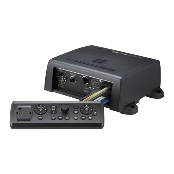
EQUIPMENT LIST Standard supply Name Type Code No. Qty. Remarks Processor Unit MPU-004 Switch Box PSD-003 Installation CP19-02100 000-034-826 Materials Spare Parts SP19-00601 001-023-040 Fuses Optional supply Name Type Code No. Remarks Switch Box PSD-003 000-034-828 Joint Box TL-CAT-012 000-167-140-10 For LAN cable exten- sion Remote Control Unit... - Page 7 EQUIPMENT LIST Name Type Code No. Remarks LAN Cable Assembly MOD-Z072-020+ 001-167-880-10 Length: 2 m MOD-Z073-030+ 000-167-171-10 Length: 3 m MOD-Z072-050+ 001-167-890-10 Length: 5 m MOD-Z072-100+ 001-167-900-10 Length: 10 m NMEA connectors SS-050505-FMF-TS001 000-168-603-10 Micro T-Connector NC-050505-FMF-TS001 000-160-507-10 Mini/Micro T-Connec- LTWMC-05BMMT-SL8001 000-168-604-10 Termination Resistor...
- Page 8 EQUIPMENT LIST This page is intentionally left blank.
-
Page 9: Mounting
MOUNTING Mounting Considerations When selecting a mounting location, keep the following points in mind: • Install the units indoors. • Locate the units away from water splash. • The operating temperature range of the processor unit is -15°C to 55°C (-27°F to 99°F). -
Page 10: How To Install The Processor Unit
1. MOUNTING How to Install the Processor Unit The Processor Unit (MPU-004) can be installed on a flat surface (such as a desktop) or on a bulkhead. 1.2.1 Bulkhead installation 1. Referring to the outline drawing at the back of this manual, drill four holes for the mounting screws (self-tapping 520, supplied as installation materials). -
Page 11: How To Install The Switch Box
1. MOUNTING How to Install the Switch Box The switch box (PSD-003) is designed to be flush mounted on a flat surface, such as a bulkhead or console. 1. Referring to the supplied outline drawing, make a cutout at the mounting location. 2. -
Page 12: How To Install Transducers
1. MOUNTING How to Install Transducers Note: For configurations using the DFF-3D, see the DFF-3D installation instructions in the operator’s manual (OME-13520-xx; xx indicates publication version). 1.4.1 How to install a transducer through the hull Transducer mounting location The thru-hull mount transducer provides the best performance of all, since the trans- ducer protrudes from the hull and the effect of air bubbles and turbulence near the hull skin is reduced. - Page 13 1. MOUNTING Installation procedure 1. With the boat hauled out of the water, mark the location chosen for mounting the transducer on the bottom of the hull. 2. If the hull is not level within 15° in any direction, fairing blocks made out of teak should be used between the transducer and hull, both inside and outside, to keep the transducer face parallel with the water line.
- Page 14 1. MOUNTING 1.4.2 How to install a transducer in the transom The optional transom mount transducer is very commonly employed, usually on rela- tively small I/O or outboard boats. Do not use this method on an inboard motor boat because turbulence is created by the propeller ahead of the transducer. DO NOT over-tighten screws, to prevent damage to the transducer.
- Page 15 1. MOUNTING 1.4.3 How to install a transducer from inside the hull The transducer may also be installed inside the hull on FRP boats. However, this in- stallation method affects the ability to detect the seabed, fish and other objects be- cause the ultrasound pulse is weakened when it passes through the hull.
- Page 16 (power switch) to turn the power on. 4) After the startup procedure completes (approx. 90 seconds), the last used display appears. Water Tap the [FURUNO] icon ( ) to show the home screen and display mode Hull plate settings. See section 3.3 for how to use the menu.
- Page 17 See section 3.3 for how to use the menu. 1) Tap the [FURUNO] icon ( to show the home screen and display mode settings. 2) Drag the menu to show [Sounder] in the menu, then tap [Sounder].
- Page 18 1. MOUNTING 1.4.4 How to install a triducer DO NOT over-tighten screws, to prevent damage to the transducer. 525STID-MSD The optional triducer 525STID-MSD is designed for thru-hull mounting. ø 79 133 2.00"-12 UN threads ø 51 Unit: mm 525STID-PWD The optional transom mount triducer 525STID-PWD can be installed by the thru-hull method or the inside-hull method.
- Page 19 1. MOUNTING Mounting location To ensure the best performance, the sensor must be submerged in aeration-free and turbulence-free water. Mount the sensor close to the centerline of your boat. On slow- er heavier displacement hulls, positioning it farther from the centerline is acceptable. Allow adequate space above the bracket for it to release and rotate the sensor up- ward.
- Page 20 1. MOUNTING If you do not know the transom angle, temporarily attach the bracket and sensor to the transom to determine if the plastic shim is needed. 11º transom angle 2º-10º 19º-22º NO SHIM transom transom angle angle shim with shim with taper down taper up...
- Page 21 1. MOUNTING 4. Repeat step 1 to ensure that the angle of the sensor is correct. Note: Do not position the sensor farther into the water than necessary to avoid increasing drag, spray, and water noise and reducing boat speed. 5.
- Page 22 1. MOUNTING 9. Route the cable to the display unit being careful not to tear the cable jacket when passing it though the bulkhead(s) and other parts of the boat. To reduce electrical interference, separate the sensor cable from other electrical wiring and "noise" sources.
-
Page 23: Wiring
WIRING Interface Connections Overview The figure below shows the connections available on the processor unit. For detailed information on connections, see the interconnection diagram at the back of this man- ual. MJ-A3SPF0019-035C MJ-A3SPF0019-035C To ship’s mains (12 to 24 V DC) Ground wire Bottom layer Bottom layer... -
Page 24: How To Protect The Interface Connections
2. WIRING How to Protect the Interface Connections All cable connectors not inside the equipment, whether exposed to weather or other- wise, should be waterproofed and secured after making the connection. By securing and waterproofing the connections, the IPx2 rating can be maintained. Disconnec- tions/loosened connections are also prevented. - Page 25 2. WIRING For unused cables 1) Cover the loose end of the cable connector with self-vulcanizing tape. Self-vulcanizing tape 2) Wrap the connector with a layer of vulcanizing tape, covering approx. 50 mm of the connected cable. Note: Confirm that the connector is covered. 50 mm Self-vulcanizing tape 3) Wrap vinyl tape over the self-vulcanizing tape on the connector.
-
Page 26: Multi Cable
2. WIRING MULTI Cable The MULTI cable is used for connection to the power switch, event switch, external buzzer. The cable has 11 wires, connect these wires referring to the table below. Wire color Connect to..White NMEA - TD_A Blue NMEA - TD_B Gray... - Page 27 2. WIRING 4. Isolate and secure unused wires as shown in section 2.2. 5. Referring to "[DATA ACQUISITION] menu" on page 3-8, set up the interface as required. 2.3.3 How to connect the external buzzer Connect the optional external buzzer (OP03-136) following the procedure below. Note: The external buzzer does not require menu settings.
-
Page 28: Drs Radar Sensor Connections
Network Connection with Other TZT Series Units Your TZT2BB is equipped with three network connectors (RJ45). Like previous NavNet series equipment, the TZT2BB is able to share Radar images and other infor- mation, across an Ethernet connection. Up to four NavNet TZtouch units may be con- nected to the same network at one time (see page iii for the details). -
Page 29: Usb Connections
Note: For more detailed image quality, FURUNO recommends using IP cameras or HDMI input instead of analog cameras or Input for connection to the TZT2BB. If using an analog camera or Input, please use an Analog-HDMI converter for more detailed image quality. -
Page 30: Nmea 2000 Connector
(OME-44870-x). Video out (external HDMI monitors) You can connect an HDMI monitor to the TZT2BB. If the monitor is a touch monitor, you can also operate the TZT2BB from the monitor. The TZT2BB is compatible with wide-screen monitors which meet the following re-... - Page 31 2. WIRING 2.8.1 How to connect the TZT2BB to NMEA 2000 equipment Below is an example of two TZT2BB units, connected via NMEA 2000 to NMEA 2000 sensors. TZT2BB TZT2BB Ethernet connection via HUB-101 Terminator Terminator NMEA 2000 backbone NMEA 2000 backbone...
- Page 32 /Command Link Plus /Helm Master How to set up the engine display Once the TZT2BB detects the Yamaha engine network, the engine can be set up on [Settings][Initial Setup][YAMAHA ENGINE SETUP]. See "[YAMAHA ENGINE SETUP] menu" on page 3-7 for details.
- Page 33 2. WIRING 2.8.4 NMEA 2000 input/output Input PGN Description 059392 ISO Acknowledgment 059904 ISO Request 060160 ISO Transport Protocol, Data Transfer 060416 ISO Transport Protocol, Connection Management - BAM group function 060928 ISO Address Claim Self Test Group Function 061184 HID Keyboard/Keypad Usage HID Mouse Report Descriptor (Proprietary PGN) 065240...
- Page 34 Note that only one TZT2BB will output NMEA 2000 data on the network at a time: the TZT2BB which is powered ON first. If that display is turned OFF, another will take its place to output the data.
- Page 35 NAVpilot General Message (I AM NAV4 SERVER) 130841 N2K System Setup Information NMEA 0183 sentence output The TZT2BB can output the following NMEA 0183 sentence to external equipment on the same network. Note that all sentences listed here use the GP talker. Sentence Description...
-
Page 36: Example System Configurations
Example System Configurations Basic plotter/fish finder installation The FURUNO GP-330B is connected to the NMEA 2000 backbone cable. The DFF3- UHD network fish finder is connected to the LAN port of the TZTBB using the standard supply cable MOD-WPAS0001-030+(3 m) and a junction box TL-CAT-012. - Page 37 2. WIRING Mid/Large-size vessels (External GPS, Fish Finder, Radar) This is a single station plotter/radar/fish finder installation. Connection to multiple sen- sors, such as the DFF3-UHD and DRS series, requires an Ethernet hub such as the HUB-101. Radar Sensor DRS6A X-Class, DRS12A X-Class, Radar Sensor DRS25A X-Class, DRS6A-NXT, DRS4DL+, DRS4D X-Class...
- Page 38 2. WIRING This page is intentionally left blank. 2-16...
-
Page 39: Equipment Setup
EQUIPMENT SETUP This chapter shows you how to set up your system according to the equipment you have connected. Touch control description The touch control depends on the screen type. The basic operations to use during the installation setup are in the following table. Operating by finger Function •... - Page 40 (power switch) on the switch box to turn the power on. 2. After the startup process completes, the last used display appears and a warning message is displayed. After reading the message, tap [OK]. 3. Tap the [FURUNO] icon ( ) to show the home screen and display mode settings.
-
Page 41: How To Set Time Zone, Time Format And Language
Before setting up your equipment, select the time zone, language and units to use on your equipment as shown below. 1. Tap the [FURUNO] icon ( ) to show the home screen and display mode settings. 2. Tap [Settings] to show the [Settings] menu. - Page 42 3. EQUIPMENT SETUP 9. Drag the menu to display the [Language] menu item, then tap [Language] on the main menu to show the language options. 10. Tap the appropriate language to use. The unit will display a confirmation mes- sage. Tap [OK] to restart the unit and apply the new language settings.This pro- cess takes approximately five minutes to optimize the system for the new language setting.
-
Page 43: How To Set Units Of Measurement
3. EQUIPMENT SETUP How to Set Units of Measurement 1. Tap the [FURUNO] icon ( ) to show the home screen and display mode settings. 2. Tap [Settings] to show the [Settings] menu. 3. Drag the main menu to display [Units], then tap [Units]. -
Page 44: Initial Setup
[Units] menu. Note 2: For configurations using the DFF-3D, refer to the instructions outlined in the operator’s manual (OME-13520-xx; xx indicates publication version). 1. Tap the [FURUNO] icon ( ) to show the home screen and display mode settings. - Page 45 3. EQUIPMENT SETUP [INSTRUMENTS SETUP] menu - Engine & Tank, Graphic Instruments menus Engine & Tank, Instruments Setup Menu item Description Options (setting range) [Engine & Tank Auto- See page 3-11. matic Setup] [Engine & Tank Manual See page 3-11. Setup] [Graphic Instruments See page 3-10.
- Page 46 Select the source for each data to input to the system. If two or more sources are connected for a data, select one using the pull-down dialog box. The FURUNO products are shown at the upper part of the list. [Sensor List] Show the information for sensors connected to your equipment.
- Page 47 (This menu does not appear on monitors connected to the HDMI OUT2 port.) Note 1: Set to [ON] on one of the TZT2BB on the network. For two or more TZT2BB, set to [ON] for only one unit. Note 2: For two or more TZT2BB, do not re-set this item once it has been set.
- Page 48 [Update Network For the service technician. Equipments] [Sirius Radio Diag- Check the satellite radio of the FURUNO BBWX SiriusXM weather receiver nostic] for proper operation. See the Operator’s Manual. [Sirius Weather Diag- Check the weather section of the FURUNO BBWX SiriusXM weather re- nostic] ceiver for proper operation.
- Page 49 Resets applicable settings to default. [OK], [Cancel] tings] [Initial Setup] menu - [Engine & Tank Automatic Setup] The TZT2BB will automatically detect engines and tanks connected to the same net- work. This is the recommended method for setting up engines and tanks. 3-11...
-
Page 50: How To Set Up The Radar
[Reset] Resets the engine/tank details to default. How to Set Up the Radar 1. Tap the [FURUNO] icon ( ) to show the home screen and display mode settings. 2. Tap [Radar] from the [Settings] menu. 3. Tap [Radar Source], then select the appropriate radar sensor. - Page 51 3. EQUIPMENT SETUP [Radar] menu - [Radar Initial Setup] Menu item Description Options (setting range) [Antenna Rotation] Select the speed of antenna rotation. Not [Auto], [24 RPM] available (greyed out) with the radar sensor DRS4DL+. [Antenna Heading Align] See "How to align the antenna [-179.9°] to [+180.0°] heading"...
- Page 52 3. EQUIPMENT SETUP Menu item Description Options (setting range) [ARPA Advanced Set- For service technician only. Do not change these settings. tings] This item is available when [TX/STBY] is [ON]. Not available (grayed out) with the radar sensor DRS4DL, DRS4DL+, or FAR-2xx8, FAR-2xx7, FAR-15x8 series radar antenna.
-
Page 53: How To Set Up The Fish Finder
Reduce range 3.650 Radar indications 2. Turn the vessel’s bow toward a target. 3. Tap the [FURUNO] icon ( ) to show the home screen and display mode settings. 4. Tap [Radar] to show the [Radar] menu. 5. Tap [Antenna Heading Align]. - Page 54 Select [ON] if you use this equipment in salt water. [OFF], [ON] [Fish Finder Select the connected fish finder.To use the built-in fish [TZT2BB], Source] finder, select [TZT2BB], which is the default nickname. [DFF1/BBDS1], The nickname can be changed in [INITIAL SET- [DFF3], UP][SENSOR LIST]. [DFF1-UHD], [DFF3-UHD] [Transducer Setup] Setup Transducer and Motion Sensor.
- Page 55 3. EQUIPMENT SETUP Options Menu item Description (setting range) [STC HF] Adjust the low (LF) or high (HF) STC frequency. 0 to +10 See the operator’s manual for details. [STC LF] 0 to +10 Note: Shown with connection of DFF3, DFF1-UHD, DFF3- UHD.
- Page 56 • [Manual]: Manually set up the transducer. • [Model]: Select the appropriate transducer model (for FURUNO or AIRMAR transducers). [Model Number] Select the appropriate model number from the list. Note: Only available when [Transducer Setup Type] is set to [Model].
- Page 57 The [Motion Sensor] menu sets up the motion sensor, which provides for stable dis- play of the seabed, schools of fish, etc. in moderate-to-rough seas. Note 1: TZT2BB does not support heaving correction. Motion sensor setup is not re- quired if [Fish Finder Source] in the [Sounder] menu is set to [Internal].
-
Page 58: Wireless Lan Settings
Bow/Stern for LF Options Menu item Description (setting range) [Motion Sensor Select the sensor connected to your TZT2BB unit. For all [NMEA2000], Type] sensors other than SC-50 and SC-110, select [NMEA0183] [NMEA2000]. Note: This menu item is not available when [Fish Finder Source] is set to [TZT2BB]. - Page 59 3. EQUIPMENT SETUP 3. Tap [Wireless LAN Settings][Wireless Mode]. 4. Tap [Connect to existing LAN]. Tap “<“ to go back one layer. 5. Turn on [Wireless] to see the available WLAN networks at the bottom of the screen. XXXX XXXX XXXX XXXX 6.
- Page 60 8. Tap [X] on the title bar to close the menu. 9. Connect to NavNet TZtouch2 at your tablet or smartphone. Use the network name and password, set up in this procedure, when connecting to the TZT2BB via tablet or smartphone. 3-22...
-
Page 61: How To Manage Your Charts
Note 2: When two or more units share an unlock code, you need to get an unlock code again if you change the [Chart Master Device]. For example, if the TZT2BB that was used as the “primary” ([Chart Master Device] setting: [ON]) is used as the “secondary”... - Page 62 3.7.2 How to update or add charts Free (USA and NOAA) and for-fee compatible charts are provided by FURUNO and Mapmedia. Go to the URL shown below to download Mapmedia charts. For FURUNO- supplied charts, contact your local FURUNO dealer.
- Page 63 3. EQUIPMENT SETUP 3.7.3 How to view your charts Tap the [FURUNO] icon ( ) to show the home screen, then tap [Charts] to display your charts catalog. Tap to show [FIlter charts] pop-up menu Tap to dowload chart unlock codes.
-
Page 64: Ip Camera Setup
How to delete charts Before replacing a chart, you should delete the old chart data on every NavNet TZtouch2/3 and TZT2BB unit. Only delete the chart data that you intend to replace or no longer require. Open the charts catalog. Tap the trashcan icon of the chart to delete. You are asked "ARE YOU SURE YOU WANT TO DELETE THIS FILE?"... - Page 65 A C K I N G L I S T 19BH-X-9853 -2 MPU-004/PSD-003-E/C N A M E DESCRIPTION/CODE № O U T L I N E Q'TY ユニット UNIT スイッチボックス PSD-003-* SWITCH BOX 000-034-830-00 制御部 MPU-004-* PROCESSOR UNIT 000-034-825-00 予備品 SPARE PARTS 予備品...
- Page 67 1/Aug/2017 H.MAKI 電子署名者 : 牧 宏昌 牧 宏昌 DN : cn=牧 宏昌, o=古野電気㈱, ou=情技 課, email=hiromasa.maki@furuno.co.jp, c=JP 日付 : 2017.08.01 17:34:20 +09'00'...
Need help?
Do you have a question about the TZT2BB and is the answer not in the manual?
Questions and answers