Advertisement
Quick Links
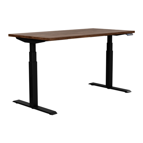
Surge
ASSEMBLY INSTRUCTIONS
Well-made wellness.
Add elevated design and sound ergonomics to any workspace with our
Surge height-adjustable table. Its rugged dual-beam base is one of the
quickest to assemble in the industry and can take on extra weight, giving
you more tabletop options — all while providing peace of mind with
enhanced safety features, including meeting BIFMA X5.5 standards.
T-Leg Model
C-Leg Model
|
|
1
C6772 Rev B
www.sitonit.net
Advertisement

Related Manuals for SitOnit Seating Surge C-Leg


Summary of Contents for SitOnit Seating Surge C-Leg
- Page 1 Surge ASSEMBLY INSTRUCTIONS Well-made wellness. Add elevated design and sound ergonomics to any workspace with our Surge height-adjustable table. Its rugged dual-beam base is one of the quickest to assemble in the industry and can take on extra weight, giving you more tabletop options —...
- Page 2 Surge ASSEMBLY INSTRUCTIONS Read the entire instruction manual before you start installation and assembly. If you have any questions regarding any of the instructions or warnings, please contact your local distributor for assistance. To report any issues with this product, contact our customer experience team at: (888) 274-8664 or sitonit@exemplis.com.
- Page 3 Surge ASSEMBLY INSTRUCTIONS IMPORTANT SAFETY INSTRUCTIONS WARNING: TO REDUCE THE RISK OF BURNS, FIRE, ELECTRIC SHOCK, OR INJURY TO PERSONS Keep Dry and Use Care When Cleaning Keep all electrical components away from water and humidity. Do not operate where aerosol (spray) products are being used or where oxygen is being administered.
- Page 4 Surge ASSEMBLY INSTRUCTIONS IMPORTANT SAFETY INSTRUCTIONS WARNING / AVERTISSEMENT RISK OF INJURY / RISQUE DE BLESSURE Max Load 265 lb, including worksurface Charge nominale 120 kg, incluant la surface de travail WARNING / AVERTISSEMENT RISK OF FIRE AND SHOCK / RISQUE D'INCENDIE ET DE CHOC Use only min Power cord to be SJT type or equivalent, 18/3 AWG minimum, 300 V, 105 degree C Utilisez uniquement un type SJT minimum ou équivalent, cordon 18 AWG minimum...
- Page 5 Surge ASSEMBLY INSTRUCTIONS IMPORTANT SAFETY INSTRUCTIONS Servicing of Double-Insulated Products In a double-insulated product, two systems of insulation are provided instead of grounding. No grounding means is provided on a double-insulated product, nor is a means for grounding to be added to the product. Servicing a double-insulated product requires extreme care and knowledge of the system and is to be done only by qualified service personnel.
- Page 6 Surge ASSEMBLY INSTRUCTIONS WARNING RISK OF DEATH AND SERIOUS INJURY Do Not Overload Table Make sure the table system is not overloaded by the weight of the tabletop and objects on table. Evenly distribute load; excess loads near the edges can reduce stability and lead to tip-over.
- Page 7 Surge ASSEMBLY INSTRUCTIONS Recommended Tools • Cordless Drill/Driver • #1 Phillips Bit • #2 Phillips Bit • 5 mm Hex Key #1 Phillips Bit #2 Phillips Bit 5 mm Hex Key C6772 Rev B www.sitonit.net...
-
Page 8: Table Of Contents
Surge ASSEMBLY INSTRUCTIONS Parts • • Hardware Top Supports (2) • • M6 x 35 mm Screws (8) Columns (2) • Feet (2) • Frame (1) Supports Frame Columns Feet T-leg foot is shown HARDWARE M6 x 35 mm Screws C6772 Rev B www.sitonit.net... -
Page 9: Hardware
Surge ASSEMBLY INSTRUCTIONS Parts • • Hardware Hand Control (1) • • M3 x 20 mm Screw (3) Control Box (1) • • M5 x 20 mm Screw (12) Cam Lock (2) • • M5 x 25 mm (2) Hairpin Clip (2) •... - Page 10 Surge ASSEMBLY INSTRUCTIONS Step 1: Attach the frame to the top supports. T-leg model is shown. C-leg step 1 is the same. When the frame is attached correctly, it will sit flush against the top support. C6772 Rev B www.sitonit.net...
- Page 11 Surge ASSEMBLY INSTRUCTIONS Step 2 (T-Leg): Loosen the set screws on the telescoping cross bars and pull the frame apart to align it with pilot holes. Refer to page 24 if tabletop does not have pilot holes. T-leg model is shown. See the following page for C-leg step 2.
- Page 12 Surge ASSEMBLY INSTRUCTIONS Step 2 (C-Leg): Loosen the set screws on the telescoping cross bars and pull the frame apart to align it with pilot holes. Refer to page 24 if tabletop does not have pilot holes. C-leg model is shown. See the previous page for T-leg step 2.
- Page 13 Surge ASSEMBLY INSTRUCTIONS Step 3 (T-Leg): Attach the frame to the tabletop. Half the frame is shown below. Attach the screws on both sides. T-leg model is shown. See the following page for C-leg step 3. 1:1 HARDWARE TOOLS M5 x 20 mm Screw #2 Phillips Bit C6772 Rev B www.sitonit.net...
- Page 14 Surge ASSEMBLY INSTRUCTIONS Step 3 (C-Leg): Attach the frame to the tabletop. Half the frame is shown below. Attach the screws on both sides. C-leg model is shown. See the previous page for T-leg step 3. 1:1 HARDWARE TOOLS M5 x 20 mm Screw #2 Phillips Bit C6772 Rev B www.sitonit.net...
- Page 15 Surge ASSEMBLY INSTRUCTIONS Step 4: Insert the tabs of the columns into the slots in the frame and push the columns towards the side beams to secure them. T-leg model is shown. C-leg step 4 is the same. Column Tab Frame Slot C6772 Rev B www.sitonit.net...
- Page 16 Surge ASSEMBLY INSTRUCTIONS Step 5: Insert the cam lock into frame long-end first. Cam lock steps need to be applied to both columns. C6772 Rev B www.sitonit.net...
- Page 17 Surge ASSEMBLY INSTRUCTIONS Step 6: Press the cam lock down and use the hair pin clip to secure it in place. Cam lock steps need to be applied to both columns. C6772 Rev B www.sitonit.net...
-
Page 18: M6 X 35 Mm Screws
Surge ASSEMBLY INSTRUCTIONS Step 7: Attach the feet to the columns. T-leg model is shown. C-leg step 7 is the same. 1:1 HARDWARE TOOLS M6 x 35 mm Screws 5 mm Hex Key C6772 Rev B www.sitonit.net... - Page 19 Surge ASSEMBLY INSTRUCTIONS Step 8: Attach the control box to the tabletop 1:1 HARDWARE TOOLS #2 Phillips Bit M5 x 25 mm Screw C6772 Rev B www.sitonit.net...
- Page 20 Surge ASSEMBLY INSTRUCTIONS Step 9: Attach the hand control to the tabletop. 1:1 HARDWARE TOOLS #1 Phillips Bit M3 x 20 mm Screw C6772 Rev B www.sitonit.net...
- Page 21 Surge ASSEMBLY INSTRUCTIONS Step 10: Route all cables from the columns to the control boxes, using the extension cables. C6772 Rev B www.sitonit.net...
- Page 22 Surge ASSEMBLY INSTRUCTIONS Step 11 (Optional): Use the wire clips and P-clips to manage cables. 1:1 HARDWARE TOOLS M3.5 x 16 mm Screw #2 Phillips Bit C6772 Rev B www.sitonit.net...
- Page 23 Surge ASSEMBLY INSTRUCTIONS Step 12: Turn the table upright and connect the A/C cable from the control box to the outlet. C6772 Rev B www.sitonit.net...
- Page 24 Surge ASSEMBLY INSTRUCTIONS Mounting Locations If the height-adjustable base is being installed on a tabletop without pilot holes, reference the tables below to determine placement. Front Offset Side Offset Side Offset Front Offset - Small Frames Table Width Offset Table Depth Offset 42"...
- Page 25 Surge SETUP INSTRUCTIONS Initialization 1-Touch Memory Feature Check all cords to ensure they 1-Touch is enabled as default. The table are fully connected. Initialization will move to the programed height with is recommended before using a single press of each memory button. table and is the first step when The following steps allow this feature to troubleshooting issues.
- Page 26 Surge SETUP INSTRUCTIONS Synchronize the Height Set the Maximum Height Display 1. Press and hold the ∆ button until it reaches the desired position. This feature allows user to recalibrate the height display so it matches the 2. Press and hold the button, then measured table height press and hold the...
- Page 27 Surge TROUBLESHOOTING INSTRUCTIONS Trouble Shooting Steps Error Code Description Possible Solution Check the connecting cables between the column Column Malfunction and control box. If the cable connectors or column receptacles are damaged, replace them. Overload Remove weight from the tabletop. Control box functioning in a severe environment.
- Page 28 Surge TROUBLESHOOTING INSTRUCTIONS Reinitialize Follow the same steps used during the initial setup on page 25 to reinitialize as a starting point to trouble-shooting. Reset Hand Control Readout Error Code Indicates Height Display is incorrectly synchronized. The following steps move the table to lowest height and correct the Height Display value 1.
Need help?
Do you have a question about the Surge C-Leg and is the answer not in the manual?
Questions and answers