Table of Contents
Advertisement
Quick Links
I N S T R U C T I O N M A N U A L
APV CU4*plus* 24V Direct Connect
Control Unit
S A F E T Y A G A I N S T E X P L O S I O N - F O R I E C E x Z O N E 2 G A S A P P L I C AT I O N S
F O R M N O . : H 3 4 5 3 1 6
R E V I S I O N : G B - 1
R E A D A N D U N D E R S TA N D T H I S M A N U A L P R I O R TO O P E R AT I N G O R S E RV I C I N G T H I S P R O D U C T.
Advertisement
Table of Contents

Related Manuals for SPX FLOW APV CU4 plus


Summary of Contents for SPX FLOW APV CU4 plus
- Page 1 I N S T R U C T I O N M A N U A L APV CU4*plus* 24V Direct Connect Control Unit S A F E T Y A G A I N S T E X P L O S I O N - F O R I E C E x Z O N E 2 G A S A P P L I C AT I O N S F O R M N O .
- Page 3 UKCA Declaration of Conformity DESIGN CENTER/MANUFACTURER: SPX Flow Technology Germany GmbH Gottlieb-Daimler-Str. 13, D-59439 Holzwickede MANUFACTURING FACILITY: SPX Flow Technology Poland sp. z o.o. Rolbieskiego 2, 85-862 Bydgoszcz, Poland AUTHORIZED REPRESENTATIVE: SPX Flow Europe Ltd. (for UKCA) Part Ground floor, Alexander House...
-
Page 5: Table Of Contents
SPX FLOW SPX FLOW_CU4.plus. 24V Direct Connect_IECEx_Zone 2_GB-1_012024_for D4. Valves.indd Content Page IECEx Specific Instructions 0.1. General Information 0.2. IECEx Specific Symbol 0.3. Authorized Use 0.4. Specific Safety Instructions 0.5. Identification of CU4** resp. CU4*plus* Control Units for use in IECEx ATEX environment 0.6. -
Page 6: General Information
The control unit must only be used with SPX FLOW valves and components recommended and authorized by SPX FLOW. Adequate transport, storage and installation, careful handling and maintenance are essential for a faultless and reliable function of the control unit. -
Page 7: Specific Safety Instructions
SPX FLOW SPX FLOW_CU4.plus. 24V Direct Connect_IECEx_Zone 2_GB-1_012024_for D4. Valves.indd IECEx Specific Instructions 0.4. Specific Safety Instructions Connecting/Disconnecting pluggable electric circuits The connecting and disconnecting of the pluggable electrical circuits including field wirings is only permitted in the absence of explosive atmosphere. Opening the device lead seal Do not open the control unit in the presence of explosive atmosphere. - Page 8 SPX FLOW SPX FLOW_CU4.plus. 24V Direct Connect_IECEx_Zone 2_GB-1_012024_for D4. Valves.indd IECEx Specific Instructions 0.4. Specific Safety Instructions In order to prevent the emergence of explosion risks observe the safety instructions of the instruction manual and adhere to the following: The required degree of protection (IP64) is guaranteed only in connection with suitable adaption sets. All pneumatic and electrical connections must be equipped with suitable connectors.
-
Page 9: Identification Of Cu4** Resp. Cu4*Plus* Control Units For Use In Iecex Atex Environment
SPX FLOW SPX FLOW_CU4.plus. 24V Direct Connect_IECEx_Zone 2_GB-1_012024_for D4. Valves.indd IECEx Specific Instructions 0.5. Identification of CU4** resp. CU4*plus* Control Units for use in IECEx ATEX environment IECEx / ATEX - identification: Equipment group II Explosion subcategory Ex ec IIB T4 Gc Ambient temperature 0 °C ≤ T ≤ +55 °C 0.6. Responsibilities... -
Page 10: Abbreviations And Definitions
SPX FLOW SPX FLOW_CU4.plus. 24V Direct Connect_IECEx_Zone 2_GB-1_012024_for D4. Valves.indd Abbreviations and Definitions Exhaust air AWG American Wire Gauge CE Communauté Européenne CU Control Unit DI Digital Input DO Digital Output EMC Electromagnetic Compatibility European Union GND Ground/mass potential IP International Protection LED Light Emitting Diode Pneumatic Air Connection NOT element NEMA National Electrical Manufacturers Association Supply Air Connection PELV Protected Extra-Low Voltage PWM Pulse-width modulation Pneumatic Air Connection... -
Page 11: Intended Use
The CU4plus Direct Connect control unit is only intended for use as described in chapter 3.1. Use beyond that described in chapter 3.1. do not comply with the regulations and SPX FLOW shall not be responsible for any damage resulting from this non-observance. -
Page 12: Welding Instructions
SPX FLOW SPX FLOW_CU4.plus. 24V Direct Connect_IECEx_Zone 2_GB-1_012024_for D4. Valves.indd Safety Instructions 2.4. Welding instructions It is generally recommended to avoid welding work in process installation in which control units are installed and connected. If welding is nonetheless required, earthing of the electrical devices in the welding area is a necessity. -
Page 13: General Terms
SPX FLOW SPX FLOW_CU4.plus. 24V Direct Connect_IECEx_Zone 2_GB-1_012024_for D4. Valves.indd General Terms 3.1. Purpose of use fig. 3.2. The control unit CU4plus Direct Connect has been developed for the control of process valves in food processing industry as well as related industries. The CU4plus Direct Connect control unit operates as interface between process control and process valve and controls the electric and pneumatic signals. - Page 14 SPX FLOW SPX FLOW_CU4.plus. 24V Direct Connect_IECEx_Zone 2_GB-1_012024_for D4. Valves.indd General Terms 3.3. Function of the individual components The installation of the control unit is undertaken by special adapters which are available for the different valves types, see chapter 5. Adapter. The snap connectors for supply air and pneumatic air to the individual cylinders at the valves are located at the outside of the control unit.
-
Page 15: Function Of The Individual Components
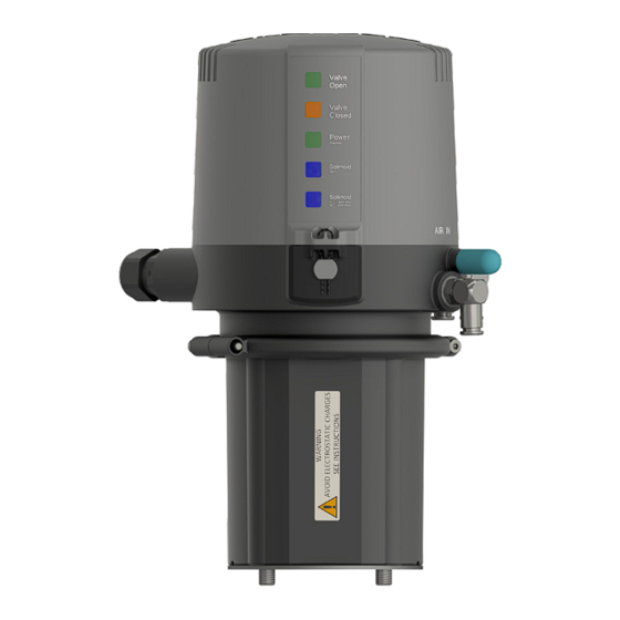
SPX FLOW SPX FLOW_CU4.plus. 24V Direct Connect_IECEx_Zone 2_GB-1_012024_for D4. Valves.indd General Terms 3.3. Function of the individual components The luminous diodes are located on the front side of the electronic module. Their signals are visibly indicated to the outside by an optical window in the cover the control unit. Beside the open and closed valve position, the existence of the operating voltage as well as different diagnostic information are indicated. -
Page 16: Mechanics And Pneumatics
SPX FLOW SPX FLOW_CU4.plus. 24V Direct Connect_IECEx_Zone 2_GB-1_012024_for D4. Valves.indd Mechanics and Pneumatics 4.1. Air connections seat valves and double seat mix proof valves 4.1.1. Function CU41plus-D4 design for D4 double seat mix proof valves without seat lift function air supply with integrated particle filter control air connection for main actuator exhaust air, with exhaust silencer CU43plus-D4 design for D4 SL double seat mix proof valves with seat lift function air supply with integrated particle filter... -
Page 17: Functional Description - Block Diagrams
SPX FLOW SPX FLOW_CU4.plus. 24V Direct Connect_IECEx_Zone 2_GB-1_012024_for D4. Valves.indd Mechanics and Pneumatics 4.3. Functional description - block diagrams 4.3.1. CU41plus-D4 for D4 double seat mix proof valves power supply + 1 Power + power supply - 2 Power - LED 6 3 DO Valve Closed... - Page 18 SPX FLOW SPX FLOW_CU4.plus. 24V Direct Connect_IECEx_Zone 2_GB-1_012024_for D4. Valves.indd Mechanics and Pneumatics 4.3. Functional description - block diagrams 4.3.2. CU43plus-D4 for D4 SL double seat mix proof valves power supply + 1 Power + power supply - 2 Power - LED 6 Operating directions of valve targets 3 DO Valve Closed...
-
Page 19: Technical Data / Standards
SPX FLOW SPX FLOW_CU4.plus. 24V Direct Connect_IECEx_Zone 2_GB-1_012024_for D4. Valves.indd Mechanics and Pneumatics 4.4. Technical data / Standards Material: PA6.6/PA12 Ambient temperature: -20 to +70 °C, -4 to +158 °F EMC 2014/30/EU (89/336/EEC) Standards and environmental audits: protective class IP 64 EN 60529/ complies with NEMA 6 DIN EN 55011... -
Page 20: Solenoid Valves
SPX FLOW SPX FLOW_CU4.plus. 24V Direct Connect_IECEx_Zone 2_GB-1_012024_for D4. Valves.indd Mechanics and Pneumatics 4.5. Solenoid valves In the base of the control unit max. 3 solenoid valves are installed. The 3/2-way solenoid valves are connected with the electronic module by moulded cables and plug connector. -
Page 21: Adapter
SPX FLOW SPX FLOW_CU4.plus. 24V Direct Connect_IECEx_Zone 2_GB-1_012024_for D4. Valves.indd Adapter Double seat mix proof valves D4, D4 SL Control Unit CU4plus Direct Connect Instruction Manual GB-0... -
Page 22: Electronic Module
Electronic Module 6.1. Function/block diagram The electronic module of the SPX FLOW CU4plus Direct Connect control unit is designed to be part of the PLC Input/Output system. It should be supplied with the same protected power supply as the other I/O devices. This power supply should not be used for other kinds of loads. - Page 23 SPX FLOW SPX FLOW_CU4.plus. 24V Direct Connect_IECEx_Zone 2_GB-1_012024_for D4. Valves.indd Electronic Module 6.1. Function/block diagram 6.1.1. CU41plus-D4 CU43plus-D4 solenoid valve 1 power supply + 1 Power + solenoid valve 2 power supply - 2 Power - LED 6 3 DO Valve Closed...
-
Page 24: Functional Description Of Connections
SPX FLOW SPX FLOW_CU4.plus. 24V Direct Connect_IECEx_Zone 2_GB-1_012024_for D4. Valves.indd Electronic Module 6.2. Functional description of connections Terminal Designation Functional Description Power+ power supply 24VDC+ Power- power supply 24VDC- O0 Digital Output PLC input valve status / closed O1 Digital Output PLC input valve status / open... -
Page 25: Technical Data
SPX FLOW SPX FLOW_CU4.plus. 24V Direct Connect_IECEx_Zone 2_GB-1_012024_for D4. Valves.indd Electronic Module 6.3. Technical data Power supply: 24 VDC +/- 20% Typical power consumption: No solenoid active, 1 feedback active 75 mA 1 solenoid active, 1 feedback active 85 mA Signal voltage inputs max. -
Page 26: Connections
SPX FLOW type switching distance acc. to SPX FLOW specification Internal hall sensors: "magnetic hall sensor" SPX FLOW UB 4.75 - 5.25 VDC switching distance acc. to SPX FLOW specification External sensors: inductive proximity switch SPX FLOW UB 4.75-5.25 VDC switching distance acc. -
Page 27: Led Indication / Indicator Lights
SPX FLOW SPX FLOW_CU4.plus. 24V Direct Connect_IECEx_Zone 2_GB-1_012024_for D4. Valves.indd Electronic Module 6.5. LED indication / Indicator lights solenoid valve 2 / solenoid valve 2 controlled blue, 1 blink upper seat * lifted upper seat lift LED 1 solenoid valve 3 / solenoid valve 3 controlled blue, 2 blinks... -
Page 28: Adjustement Of Valve Profiles
SPX FLOW SPX FLOW_CU4.plus. 24V Direct Connect_IECEx_Zone 2_GB-1_012024_for D4. Valves.indd Electronic Module 6.6. Adjustement of valve profiles The adjustment of valve profiles is carried out with the Service Software CU4plus Toolbox (see CU4plus Toolbox manual). For the different process valves different logic profiles exist. These differ in view of the detection of the feedback and the logic profile of the valve. - Page 29 SPX FLOW SPX FLOW_CU4.plus. 24V Direct Connect_IECEx_Zone 2_GB-1_012024_for D4. Valves.indd Electronic Module 6.7. Data signals 6.7.1. Mix proof valve D4 operating main stroke downwards main stroke valve operating direction: downwards lower shaft signal S3 linear sensor 1 valve target signal S4 upper shaft signal S2 linear sensor 2 valve target signal S1 linear sensor 1 linear sensor 2 Output valve linear sensor 2 / (Teach data) linear sensor 1 / (Teach date) tolerance...
- Page 30 SPX FLOW SPX FLOW_CU4.plus. 24V Direct Connect_IECEx_Zone 2_GB-1_012024_for D4. Valves.indd Electronic Module 6.7. Data signals 6.7.2. Mix proof valve D4 SL operating main stroke downwards upper seat lift upwards lower seat lift downwards main stroke valve operating direction: downwards lower shaft signal S3 linear sensor 1 valve target signal S4 upper shaft signal S2 linear sensor 2 valve target signal S1 linear sensor 1 linear sensor 2 Output valve status linear sensor 2 / (Teach data)
-
Page 31: Data Signals
SPX Flow using the article number H333470. The latest version of the Toolbox Software is always available from the SPX Flow F&B Sharepoint. Please contact your SPX Flow Sales representative. This software is designed for PC system software Windows 7, Windows 8.1, Windows 10. -
Page 32: Seat Pulsation - Efficiency In Cleaning
SPX FLOW SPX FLOW_CU4.plus. 24V Direct Connect_IECEx_Zone 2_GB-1_012024_for D4. Valves.indd Electronic Module 6.9. Seat Pulsation - Efficiency in Cleaning For increasing seat cleaning efficiency there is a function called "Pulsation". With this function, the seat lifts can be operated in plusation mode if the PLC signal activates the seat lift. -
Page 33: Valve Position Indication
SPX FLOW SPX FLOW_CU4.plus. 24V Direct Connect_IECEx_Zone 2_GB-1_012024_for D4. Valves.indd Valve Position Indication 7.1. Continuously measuring valve position measuring system For the internal detection of the valve position indication, a contact- free operating linear sensor is used which is actuated via the magnetic switching cam installed at the valve rod. The nominal measuring range of the measuring system amounts to 0 - 72 mm, relative repetitive accuracy <... -
Page 34: Adjustment Of Valve Position Indication / Teach-In
SPX FLOW SPX FLOW_CU4.plus. 24V Direct Connect_IECEx_Zone 2_GB-1_012024_for D4. Valves.indd Valve Position Indication 7.3. Adjustment of valve position indication / Teach-in The continuously measuring valve position measuring system is tought via a reference valve movement. The respective positions for the closed and open valve position as well as for further valve positions, e.g. seat lifting, are travelled to and the corresponding position of the sensor system is permanently stored in the memory of the electronic module. -
Page 35: Use Of External Sensors
SPX FLOW SPX FLOW_CU4.plus. 24V Direct Connect_IECEx_Zone 2_GB-1_012024_for D4. Valves.indd Valve Position Indication 7.3.1. To be observed before Teach-in: Corresponding switching cam is mounted to the valve guide rod. Note! Caution! The switching cam is not identical with the standard CU switching cam! CU4plus Direct Connect control unit is not duly installed on the valve. -
Page 36: Cu Assembly And Startup
SPX FLOW SPX FLOW_CU4.plus. 24V Direct Connect_IECEx_Zone 2_GB-1_012024_for D4. Valves.indd CU Assembly and Startup 8.1. Double seat mix proof valves D4, D4 SL CU cover linear sensor CU41/CU43plus linear operating cam with magnet M1 sensor screws clamp ring adapter operating cam with magnet M2 actuator Assembly of the control unit on the valve 1. Assemble the magnet M2 on the upper shaft under the stop screw. - Page 37 SPX FLOW SPX FLOW_CU4.plus. 24V Direct Connect_IECEx_Zone 2_GB-1_012024_for D4. Valves.indd CU Assembly and Startup 8.1.1 Pneumatic connection Supply air: Caution! Shut off the compressed air supply before connecting the air hose! Make sure that the air hose is professionally cut to length. Use a hose cutter for this purpose.
- Page 38 8.1.3 Connection of external proximity switches The electric connection of the proximity switches specified by lever SPX FLOW is undertaken according to the terminal layout described in chapter 6. The mechanic assembly of the proximity switches is carried out at the actuator of the corresponding double seat valves.
-
Page 39: Accessories And Tools
SPX FLOW SPX FLOW_CU4.plus. 24V Direct Connect_IECEx_Zone 2_GB-1_012024_for D4. Valves.indd Accessories and Tools Assembly/disassembly - adapter on valve actuator: • hexagon socket wrench 6 mm • screwdriver 4 mm Assembly/disassembly – CU on adapter: • hexagon socket wrench 3 mm Assembly/disassembly – electronic module: • Torx wrench TX20 • screwdriver 3.5 mm Assembly/disassembly – feedback unit: •... -
Page 40: Service
SPX FLOW SPX FLOW_CU4.plus. 24V Direct Connect_IECEx_Zone 2_GB-1_012024_for D4. Valves.indd 10. Service 10.1. Dismantling Before disassembly, verify the following items: • The valve must be in safety position and must not be controlled! • Shut off air supply! • Cut off current to control unit, i.e. interrupt the supply voltage! Solenoid valve (4, 5, 6) Open the CU cover by turning in counterclockwise direction. -
Page 41: Trouble Shooting
SPX FLOW SPX FLOW_CU4.plus. 24V Direct Connect_IECEx_Zone 2_GB-1_012024_for D4. Valves.indd 11. Trouble Shooting Failure Remedy Valve position is not indicated. Carry out Teach-in. Check fastening of magnetic switching cam. Check adjusted logic profile and process valve. Feedback via proximity Check positioning of proximity switches is missing. - Page 42 SPX FLOW SPX FLOW_CU4.plus. 24V Direct Connect_IECEx_Zone 2_GB-1_012024_for D4. Valves.indd 11. Trouble Shooting Failure Remedy Control Unit CU41 installed on Single seat, Double seal and Double seat valves Valve position movement is Check if right control unit is missing with actuated solenoid installed. Check label in type valve. window of control unit:...
-
Page 43: Iecex / Ccc Certificate Of Conformity
SPX FLOW SPX FLOW_CU4.plus. 24V Direct Connect_IECEx_Zone 2_GB-1_012024_for D4. Valves.indd 12. IECEx / CCC Certificate of Conformity Please see attachment. 13. Spare Parts Lists The reference numbers of spare parts for the different control unit designs and adapters are included in the attached spare parts drawings with corresponding lists. - Page 45 Certificate history: Current Status: Issue No: 0 Date of Issue: 2023-09-11 Applicant: SPX Flow Technology Germany GmbH Gottlieb-Daimler-Str. 13 59439 Holzwickede Germany Control unit resp. Double seat valve resp. Assembly Equipment: Optional accessory: Control unit type CU4** resp. CU4*plus* resp. Double seat valve type D4* resp. Assembly type D4*-CU4**/CU4*plus* Type of Protection: Equipment protection by increased safety “ec”;...
- Page 46 Date of issue: 2023-09-11 Issue No: 0 Manufacturer: SPX Flow Technology Germany GmbH Gottlieb-Daimler-Str. 13 59439 Holzwickede Germany SPX Flow Technology Germany SPX Flow Technology Poland Sp. z Manufacturing locations: GmbH o.o. Gottlieb-Daimler-Str. 13 Rolbieskiego 2 59439 Holzwickede Bydgoszcz 85-862...
- Page 47 IECEx Certificate of Conformity Certificate No.: IECEx TUN 22.0020X Page 3 of 3 Date of issue: 2023-09-11 Issue No: 0 EQUIPMENT: Equipment and systems covered by this Certificate are as follows: Description: The control unit type CU4** resp. CU4*plus* is provided for controlling process valves in hazardous areas, it used as an interface between the process control and the process valve and operates the electrical and pneumatic signals.
- Page 48 TÜV NORD CERT GmbH Hannover Office Am TÜV 1 30519 Hannover Germany Page 1 of 5 Attachment to IECEx TUN 22.0020X issue No.: 0 General product information: Description: The control unit type CU4** resp. CU4*plus* is provided for controlling process valves in hazardous areas, it used as an interface between the process control and the process valve and operates the electrical and pneumatic signals.
- Page 49 Internal Mass potential for sensor voltage supply Internal Linear Linear sensor for valve position detection (for sensor suitable SPX FLOW sensor, only!) Internal Solenoid valve 1 (main valve) Internal Solenoid valve 2 (upper seat lift) Internal Solenoid valve 3 (lower seat lift)
- Page 50 TÜV NORD CERT GmbH Hannover Office Am TÜV 1 30519 Hannover Germany Page 3 of 5 Attachment to IECEx TUN 22.0020X issue No.: 0 For the control unit type CU4* plus 24V Direct Connect: Internal / External Terminal Designation Functional description External Power+ Power supply 24V d.c.
- Page 51 TÜV NORD CERT GmbH Hannover Office Am TÜV 1 30519 Hannover Germany Page 4 of 5 Attachment to IECEx TUN 22.0020X issue No.: 0 For the control unit type CU4*24V Direct Connect: Internal / External Terminal Designation Functional description External Power+ Power supply 24V d.c.
- Page 52 TÜV NORD CERT GmbH Hannover Office Am TÜV 1 30519 Hannover Germany Page 5 of 5 Attachment to IECEx TUN 22.0020X issue No.: 0 Thermal data: Control unit type CU4** resp. CU4*plus*: Permissible ambient temperature range during operation: 0 °C ≤ Ta ≤ +55 °C Double seat valve type D4*: The permissible ambient temperature range as process temperature (medium or cleaning solutions temperature) depending on the temperature class is shown in the following table:...
- Page 54 SPX(Shanghai) Flow Technology Company Limited Applicant No.666, Fengjin Road, Xidu Industry park, Fengxian District, Address Shanghai China SPX Flow Technology Poland Sp. z o.o. Manufacturer Stanisława Rolbieskiego 2, Bydgoszcz 85-862, Poland Address SPX Flow Technology Poland Sp. z o.o. Production Factory Stanisława Rolbieskiego 2, Bydgoszcz 85-862, Poland...
- Page 55 No.:2023312304001783 Page 1 of 8 Product information: This certificate covers the following models: - CU4** , CU4*plus* Nomenclature: 1) CU4** 1: 1 solenoid 2: 1 solenoid, 1NOT element 3: 3 solenoids AS-interface 24V Direct Connect 2) CU4*plus* plus 1: 1 solenoid 2: 1 solenoid, 1NOT element 3: 3 solenoids AS-interface...
- Page 56 No.:2023312304001783 Page 2 of 8 Control unit type CU4*AS-interface Internal / Terminal Designation Functional description External External AS-i + Connection AS-i network (26.5 V…31.6 V d.c.) External AS-i - Connection AS-i network (GND) Internal 5 VDC Voltage supply for proximity switches Internal Sensor 1 Signal sensor 1 (closed valve position)
- Page 57 No.:2023312304001783 Page 3 of 8 External SV Digital Output Common External DI0 Digital Input PLC output to activate solenoid 1 / main valve External DI1 Digital Input PLC output to activate solenoid 2 / upper seat lift External PLC output to activate solenoid 3 / lower DI2 Digital Input seat lift External...
- Page 58 Internal Mass potential for sensor voltage supply Internal Linear Linear Linear sensor for valve position detection (for sensor sensor suitable SPX FLOW sensor, only!) Internal Solenoid valve 1 (main valve) Internal Solenoid valve 2 (upper seat lift) Issued date: 2023-10-27...
- Page 59 No.:2023312304001783 Page 5 of 8 Internal Solenoid valve 3 (lower seat lift) Internal Optional connection - pressure sensor External Service port Connection serial/USB converter for CU4plus toolbox software Control unit type CU4* plus 24V Direct Connect Internal / Terminal Designation Functional description External External...
- Page 60 No.:2023312304001783 Page 6 of 8 Internal Signal SPX prox. sensor Internal Potential for SPX prox. sensor / linear sensor Internal Linear sensor Internal PWM Output Solenoid valve 1 (main valve) Internal PWM Output Solenoid valve 2 (upper seat lift) Internal PWM Output Solenoid valve 3 (lower seat lift) External...
- Page 61 No.:2023312304001783 Page 7 of 8 Internal Sensor 1 Linear Sensor 1 Internal Sensor 2 Sensor Signal 2 Internal Mass potential for sensor supply Internal PWM Output Solenoid valve 1 (main valve) Internal PWM Output Solenoid valve 2 (upper seat lift) Internal PWM Output Solenoid valve 3 (lower seat lift)
- Page 62 No.:2023312304001783 Page 8 of 8 - Measures have to be taken, external to the control unit type CU4** resp. CU4*plus*, to provide a transient protection that ensures that the rated voltage, connected to the power supply terminals, is not exceeded by more than 40%. - See instruction for other information.
- Page 73 F: (+48) 52 525 99 09 SPX FLOW reserves the right to incorporate the latest design and material changes without notice or obligation. Design features, materials of construction and dimensional data, as described in this manual, are provided for your information only and should not be relied upon unless confirmed in writing.
Need help?
Do you have a question about the APV CU4 plus and is the answer not in the manual?
Questions and answers