Table of Contents
Advertisement
Quick Links
Advertisement
Table of Contents

Related Manuals for SPX FLOW APV DELTA CPV


Summary of Contents for SPX FLOW APV DELTA CPV
- Page 1 I N S T R U C T I O N M A N U A L APV DELTA CPV C O N S TA N T P R E S S U R E D I A P H R A G M VA LV E F O R M N O .
- Page 3 Directives 2006/42/EC (superseding 89/392/EEC and 98/37/EC) and ProdSG (superseding GPSG - 9.GPSGV). For official inspections, SPX FLOW presents a technical documentation according to Appendix VII of the Machinery Directive, this documentation consisting of documents of the development and construction, description of measures taken to meet the conformity and to correspond with the basic requirements on safety and health, incl.
-
Page 5: Table Of Contents
APV_CPV_UK-3_112017.indd Table of Contents Page General Terms Safety Instructions Intended Use Application and Mode of Operation Cleaning 5.1. Cleaning CPV-o: 5.2. Cleaning CPV-c: Installation 4–5 Welding Instructions Dimensions / Weights Technical Data 7–8 8.1. General terms 8.2. Compressed air quality 8.3. -
Page 7: General Terms
APV_CPV_UK-3_112017.indd General Terms This instruction manual has to be read carefully and observed by the competent operating and maintenance personnel. For design reasons, the technical operating ranges of the valve with regard to operating pressures and temperatures have to be kept. We have to point out that we will not accept any liability for damage or malfunctions resulting from the non-compliance with this instruction manual. -
Page 8: Application And Mode Of Operation
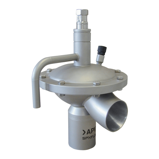
APV_CPV_UK-3_112017.indd Application and Mode of Operation The CPV constant pressure diaphragm valve forms part of the pneumatically operated pressure regulating valves and pressure holding valves which keep process pressures constant in process technological plants of the food and beverage as well as of the pharmaceutical and chemical industries (e.g. -
Page 9: Cleaning
APV_CPV_UK-3_112017.indd Cleaning Cleaning of the CPV valves is undertaken with pipeline cleaning. The following has to be considered for the different valve variants. Δp of about 3bar must be kept. Cleaning CPV-o: At a max. CIP line pressure up to 3 bar, the valve is not controlled with pneumatic air. -
Page 10: Welding Instructions
APV_CPV_UK-3_112017.indd Installation Welding Instructions Before welding of the valves, the valve insert must be dismantled from the housing. See to a careful handling to avoid damage to the parts. Welding may only be carried out by certified welders (DIN EN ISO 9606-1). -
Page 11: Dimensions / Weights
APV_CPV_UK-3_112017.indd Dimensions / Weights CPV - o/c booster Ø E CPV - o/c Ø D Ø D Ø 12x1 Ø 12x1 Ø C Ø C inst. dimension weight ref.-No. Ø C Ø D Ø E X in mm in kg CPV-o 20-16-444/.. - Page 12 APV_CPV_UK-3_112017.indd Technical Data 8.1. General terms Operating pressure: 7 bar Max. control air pressure for CPV: 6 bar Max. control air pressure for CPV with booster: 4 bar Operating temperature: 135°C short-term: 140°C Air connections: G1/8“ 8.2. Compressed air quality Quality class according to DIN ISO 8573-1 - content of solid particles: quality class 3,...
-
Page 13: Technical Data
APV_CPV_UK-3_112017.indd Technical Data 8.3. Pressure ratio diagram (air/product) air (bar) CPV-o CPV-c product (bar) 2,0 3,0 8.4. Pressure loss curve CPV ΔP valve stroke 15 mm kvs = 25 m³/h (bar) CPV-o (m³/h) ΔP valve stroke 15 mm kvs = 22,5 m³/h (bar) CPV-c (m³/h) -
Page 14: Materials
APV_CPV_UK-3_112017.indd Materials Housing, intermediate piece and cover out of stainless steel: 1.4404 (DIN EN 10088) Screws: 1.4301 (DIN EN 10088) Seals: standard design EPDM Diaphragms: composite material TFM / EPDM 10. Maintenance The maintenance intervals depend on the corresponding application (product, temperature) and are to be determined by the operator himself carrying out temporary checks. -
Page 15: Service Instructions
APV_CPV_UK-3_112017.indd Service Instructions The item numbers refer to the spare parts drawings (DIN design: RN 01.177). 11.1. Disassembly from the line system 1. Depressurize the product and air lines. 2. Dismantle the air supply at (9). 3. Loosen the nuts (18) and remove the hexagon screws (17). 4. -
Page 16: Installation Of Seals And Assembly Of Valve
APV_CPV_UK-3_112017.indd Service Instructions 11.3. Installation of seals and assembly of valve 1. Insert the o-ring (14) into the groove of the shaft (3 or 4). 2. Insert the guide bushings (11) and the o-ring (15, 16) into the housing cover (8). 3. -
Page 17: Dismantling Of Booster
APV_CPV_UK-3_112017.indd Service Instructions 11.4. Dismantling of booster The item numbers refer to the spare parts drawings RN 01.177. 1. Depressurize the product line and air supply line. 2. Dismantle the air supply line (9, 19.7). 3. Remove the hexagon screws (19.6). 4. -
Page 18: Trouble Shooting
Air leakage from the leakgae drain and o-rings (15, 16). When damaged seals are changed, generally all seals should be replaced. For valve service actions SPX FLOW supplies complete seal kits. (see spare parts lists) . 13. Spare Parts Lists... - Page 24 F: (+48) 52 525 99 09 SPX FLOW reserves the right to incorporate the latest design and material changes without notice or obligation. Design features, materials of construction and dimensional data, as described in this manual, are provided for your information only and should not be relied upon unless confirmed in writing.
Need help?
Do you have a question about the APV DELTA CPV and is the answer not in the manual?
Questions and answers