Table of Contents
Advertisement
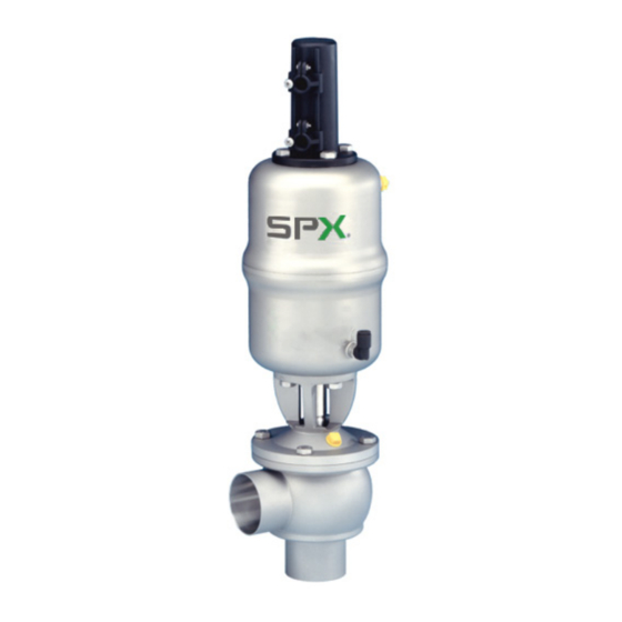
APV DELTA SD4 DN25-100, 1"-4"
D O U B L E S E A L VA LV E
S A F E T Y A G A I N S T E X P L O S I O N - F O R S P E C I F I C AT E X - A P P L I C AT I O N S
F O R M N O . : H 3 3 0 1 2 6
R E V I S I O N : U K - 0 - AT E X
Scan for SD4 Valve
Maintenance Video
R E A D A N D U N D E R S TA N D T H I S M A N U A L P R I O R TO O P E R AT I N G O R S E RV I C I N G T H I S P R O D U C T.
I N S T R U C T I O N M A N U A L
Advertisement
Table of Contents

Related Manuals for SPX FLOW APV DELTA SD4 Series


Summary of Contents for SPX FLOW APV DELTA SD4 Series
- Page 1 I N S T R U C T I O N M A N U A L APV DELTA SD4 DN25-100, 1”-4” D O U B L E S E A L VA LV E S A F E T Y A G A I N S T E X P L O S I O N - F O R S P E C I F I C AT E X - A P P L I C AT I O N S F O R M N O .
- Page 3 Directive on the Protection against Explosion 2014/34/EU ATEX (superseding 94/9/EC) for Equipment Category -/2G IIB TX For official inspections, SPX FLOW presents a technical documentation according to Appendix VII of the Machinery Directive, this documentation consisting of documents of the development and construction, description of measures taken to meet the conformity and to comply with the basic requirements on safety and health, incl.
-
Page 5: Table Of Contents
APV_SD4_ATEX_UK-0_122018.indd Content Page General Terms 1.1. Symbols 1.2. Responsibility for ATEX certification - Scope of supply Safety Instructions 3 - 4 Identification of valves, Temperature classes, Responsibilites 5 - 6 3.1. Identification of valves for application in ATEX environment 3.2. Temperature classes and permissible temperatures 3.3. Responsibilities Intended Use Mode of Operation 5.1. General terms Cleaning 6.1. Cleaning recommendation 6.2. Leakage chamber 6.3. Cleaning recommendation - leakage chamber 6.4. -
Page 7: General Terms
1.2. Responsibility for ATEX certification - scope of supply SPX FLOW will be held responsible only for the valves supplied and selected according to the operating conditions indicated by the customer or end user and as stated in the order confirmation. If in doubt, contact your local supplier. -
Page 8: Safety Instructions
Danger to life! Actuators which are no longer used or defective must be diposed in professional manner. Defective actuators must be returned to your SPX FLOW representative for their professional disposal and free of charge for you. Please address to your local SPX FLOW representative. -
Page 9: Safety Instructions
APV_SD4_ATEX_UK-0_122018.indd Safety Instructions Installation, connection, start-up, maintenance and repair work must only be carried out by qualified personnel. The following aspects must be observed: The instructions of this manual together with all relevant instructions for the components, equipment and installations installed. Warnings and installations fixed to the components. The specific regulations for and requirements to the system in which the valve is installed. The currently valid regional, national and international regulations. -
Page 10: Temperature Classes And Permissible Temperatures
All data (temperature classes) refer to an ambient temperature of 0°C to 40°C. If the ambient temperature is above 40°C, the temperature difference must be adjusted. In all cases, contact your responsible SPX FLOW representative! Double seal valve DELTA SD4-ATEX... -
Page 11: Responsibilities
APV_SD4_ATEX_UK-0_122018.indd Identification of valves, Temperature classes, Responsibilities 3.3. Responsibilites It is within the operator`s responsibility to ensure that the specified product temperatures are not exceeded and that regular inspections and maintenance are carried out to provide for proper function of the valve. Intended Use The intended use as field of application of the DELTA SD4 double seal valve is the shut-off of line sections, especially in beverage and food installations. -
Page 12: Mode Of Operation
APV_SD4_ATEX_UK-0_122018.indd Mode of Operation 5.1. General terms DELTA SD4 double seal valves have been developed for use in the brewing and beverage, dairy and food industries as well as for SD4 double seal valve chemical and pharmaceutical applications. with valve position indication The valves are designed for universal applications and stand out for their increased mechanical reliability and absolute ease of service. -
Page 13: Cleaning
APV_SD4_ATEX_UK-0_122018.indd Cleaning For the cleaning of SD4 valves, distinction is made between two areas. 6.1. The flow chambers The passages of the valve are cleaned by the cleaning liquid during cleaning of the connected pipelines. 6.2. The leakage chamber (fig. 6.2.) Cleaning of the leakage chamber is undertaken via the leakage valves. -
Page 14: Hosing Of Leakage Valves
APV_SD4_ATEX_UK-0_122018.indd Cleaning Depending on the degree and substances of soiling, cleaning fig. 6.4. liquids, times and processes must be scheduled for the individual application. The compatibility of the individually selected cleaning processes and liquids with the respective seal material must be verified. 6.4. Hosing of leakage valves: AIR IN : air supply. AIR IN Installation 7.1. General terms Installation must be undertaken in such a way that liquids can drain off and should preferably be carried out in vertical position. -
Page 15: Welding Instructions
APV_SD4_ATEX_UK-0_122018.indd Installation 7.2. Welding instructions Before welding of the valve, the valve insert must be dismantled from the housing. Careful handling to avoid damage to the parts is necessary. Welding should only be carried out by certified welders (DIN EN ISO 9606-1). -
Page 16: Dimensions / Weights
APV_SD4_ATEX_UK-0_122018.indd Dimensions / Weights housing variants SD 41 Ø K SD 42 Dimensions in mm Weight in kg ∅ K ∅ Di Inch 1" 22,6 1,5" 34,9 2" 47,6 2,5" 60,3 3" 72,9 4" 97,6 Double seal valve DELTA SD4-ATEX Instruction Manual: UK - rev. 0... - Page 17 APV_SD4_ATEX_UK-0_122018.indd Dimensions / Weights housing variants SDE 43 Ø K SDE 44 Dimensions in mm Weight in kg ∅ K ∅ Di 14,5 411,5 20,5 435,5 26,5 490,5 523,0 42,5 597,5 636,0 Inch 1" 12,5 22,6 56,6 404,1 1,5" 19,05 34,9 68,9 428,9 2" 25,4 47,6 81,6 486,0 2,5"...
- Page 18 APV_SD4_ATEX_UK-0_122018.indd Technical Data 9.1. General data Product-wetted parts: 316 L, 1.4404 (DIN EN 10088) Other parts: 1.4301 (DIN EN 10088) Seals: standard design: EPDM option: HNBR, VMQ, FPM Max. line pressure: 10 bar Operating pressure: depending on actuator - see pos. 9.6 Max.
- Page 19 APV_SD4_ATEX_UK-0_122018.indd Technical Data 9.3. SD4 Closing times Closing times in sec Pneumatic air pressure 6bar Hose length 1 m Inch 10 m 1" 1 sec. 1,5 sec. 1,5" 1 sec. 1,5 sec. 2" 1 sec. 1,5 sec. 2,5" 1 sec. 2,5 sec. 3" 1 sec. 3,0 sec. 4" 1,2 sec. 3,5 sec. Times mentioned are only approximate values from sample measurements.
- Page 20 APV_SD4_ATEX_UK-0_122018.indd Technical Data 9.5. Pneum. air compsuption at 6 bar control pressure Actuator NL per stroke Ø 74mm Ø 110mm Ø 165mm 9.6. DELTA SD4 calculatory product pressures in (bar) at 6 bar control air pressure - valve normally closed (NC) or in case of compressed air failure SD 41 - FS Ø actuator in mm Inch Ø 74 Ø 110 Ø 165 1" 16,0 1,5" 2" 11,2 2,5" 11,6 3" 4" = standard actuator Double seal valve DELTA SD4-ATEX Instruction Manual: UK - rev.
-
Page 21: Technical Data
APV_SD4_ATEX_UK-0_122018.indd Technical Data 9.7. DELTA SD4 kvs values in m³/h SD41, SD42 SD41, SD42 SDE43, SDE44 SDE43, SDE44 Inch 1" 1,5" 2" 2,5" 3" 4" Double seal valve DELTA SD4-ATEX Instruction Manual: UK - rev. 0... -
Page 22: Maintenance
APV_SD4_ATEX_UK-0_122018.indd 10. Maintenance The maintenance intervals depend on the corresponding Scan for SD4 Valve Maintenance Video application and are to be determined by the operator himself carrying out temporary checks. The valve must not be cleaned with products containing abrasive or polishing material. - Page 23 APV_SD4_ATEX_UK-0_122018.indd 10. Maintenance Additionally required maintenance for applications in ATEX environment SD4 Valve Valve maintenance for Note actuator with spring Functional test, 1 x per year visual inspection of valve stroke and control of abnormal running noise of spring Change interval of actuator In case of damage, incomplete actuator movement, considerable running noise of spring as well as...
-
Page 24: Service Instructions
APV_SD4_ATEX_UK-0_122018.indd 11. Service Instructions Corresponding spare parts see Spare parts list: RN ATEX 054.62 11.1. Dismantling from the line system Before start of assembly the operator must make sure that an valve position indicator explosive atmohsphere does not exist (detection/measurement of potential concentration of hazardous substances). Alternatively, use spark-resistant tools! actuator screw 1. Shut off line pressure and drain lines if possible. actuator 2. - Page 25 APV_SD4_ATEX_UK-0_122018.indd 11. Service Instructions 11.3. Installation of seals and Assembly of valve 1. Insert the guide bush into the yoke. fig. 11.3.1. Afterwards, insert the shaft seal and press in the slightly greased seat seal (see fig. 11.3.1.). See to the correct installing position. guide bush 2. Install the yoke at the actuator. yoke 3.
-
Page 26: Service Instructions - Leakage Valves
APV_SD4_ATEX_UK-0_122018.indd 12. Service Instructions - Leakage valves 12.1. Maintenance of leakage valves The item numbers refer to the corresponding spare parts list leakage valves SD4 RN: 01.054.67 1. Disconnect the pneumatic air hoses at the two leakage valves. 2. Shut off and discharge the CIP supply line. 3. Remove the CIP supply and discharge lines from the leakage valves. -
Page 27: Service Instructions - Actuator
APV_SD4_ATEX_UK-0_122018.indd 13. Service Instructions - Actuator fig. 13.1. Spare parts list: RN01.054.86 seal screw 13.1. Maintenance of actuator (fig. 13.1.) piston rod v-seal 1. Remove the air hoses from the actuator. o-ring 2. Unscrew the two seal screws with a spanner SW30 while holding up the actuator with a strap wrench. 13.2. Installation of seals and Assembly of Actuator 1. -
Page 28: Reconstruction Of Actuator
APV_SD4_ATEX_UK-0_122018.indd 14. Reconstruction of Actuator With SD4 valves, the size of the actuator can be changed. Observe the respective line pressure, see table 9.6, to increase or decrease the actuator sizes (Ø 74 mm, Ø 110 mm, Ø 165 mm). 14.1. Reconstruction of actuator Disassembly Disassembly is carried out as described in chapter 11. -
Page 29: Assembly Tool
APV_SD4_ATEX_UK-0_122018.indd 15. Installation of Seat seal By means of the assembly tool, the seat seal (11) can be installed, only (see fig. 15). At first, this seat seal must be mounted onto the fig. 15. valve shaft. seat seal (12) valve shaft Afterwards, the seat seal (12) must be manually inserted into the groove, see item 15.2. - Page 30 APV_SD4_ATEX_UK-0_122018.indd 15. Installation of Seat seal 15.2. Manual installation of seat seal (pos. 12) Before assembly, the seat seal must be provided with a thin layer of grease. The receiving groove for the seat seal must not be greased. Clamp the valve shaft in a vice. The valve shaft must not be damaged. Use protective braces.
-
Page 31: Trouble Shooting
APV_SD4_ATEX_UK-0_122018.indd 16. Trouble Shooting Failure Remedy Replace seat seal. Valve is untight, leakage via leakage valves Check line pressure: Admissible line pressure see chapter 9. Replace o-rings. Leakage at leakage valve cylinder see RN 01.054.67 Check cleaning liquid supply. Leakage between housing and yoke flange Replace housing seals. -
Page 44: Double Seal Valve
P: (+48) 52 566 76 00 F: (+49) (0) 2301-9186-300 F: (+48) 52 525 99 09 SPX FLOW reserves the right to incorporate the latest design and material changes without notice or obligation. Scan for SD4 Valve Maintenance Video Design features, materials of construction and dimensional data, as described in this manual, are provided for your information only and should not be relied upon unless confirmed in writing.
Need help?
Do you have a question about the APV DELTA SD4 Series and is the answer not in the manual?
Questions and answers