Table of Contents
Advertisement
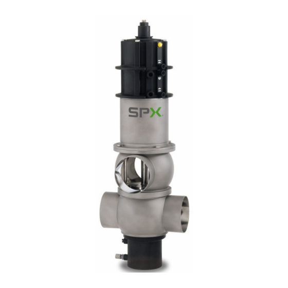
APV DELTA DA3+ DN40-100, 1.5"-4"
D O U B L E S E AT VA LV E
S A F E T Y A G A I N S T E X P L O S I O N - F O R S P E C I F I C AT E X - A P P L I C AT I O N S
F O R M N O . : H 3 3 1 5 2 4
R E V I S I O N : U K - 0 - AT E X
Scan for DA3+ Valve
Maintenance Video
R E A D A N D U N D E R S TA N D T H I S M A N U A L P R I O R TO O P E R AT I N G O R S E RV I C I N G T H I S P R O D U C T.
I N S T R U C T I O N M A N U A L
Advertisement
Table of Contents

Related Manuals for SPX FLOW APV DELTA DA3+


Summary of Contents for SPX FLOW APV DELTA DA3+
- Page 1 I N S T R U C T I O N M A N U A L APV DELTA DA3+ DN40-100, 1.5”-4” D O U B L E S E AT VA LV E S A F E T Y A G A I N S T E X P L O S I O N - F O R S P E C I F I C AT E X - A P P L I C AT I O N S F O R M N O .
- Page 3 Directive on the Protection against Explosion 2014/34/EU ATEX (superseding 94/9/EC) for Equipment Category -/2G IIB TX For official inspections, SPX FLOW presents a technical documentation according to Appendix VII of the Machinery Directive, this documentation consisting of documents of the development and construction, description of measures taken to meet the conformity and to correspond with the basic requirements on safety and health, incl.
-
Page 5: Table Of Contents
APV_DA3+_ATEX_UK-0_022018.indd Content Page General Terms 1.1. Symbols 1.2. Responsibility for ATEX certification - Scope of supply Safety Instructions 3 - 4 Identification of valves, Temperature classes, Responsibilites 5 - 6 3.1. Identification of valves for application in ATEX environment 3.2. Temperature classes and permissible temperatures 3.3. Responsibilities Intended Use Mode of Operation 7 - 8 5.1. General terms 5.2. Valve in “closed” position 5.3. Valve in "open" position Auxiliary Equipment 6.1. -
Page 7: General Terms
1.2. Responsibility for ATEX certification - scope of supply SPX FLOW will be held responsible only for the valves supplied and selected according to the operating conditions indicated by the customer or end user and as stated in the order confirmation. If in doubt, contact your local supplier. -
Page 8: Safety Instructions
Danger to life! Actuators which are no longer used or defective must be diposed in professional manner. Defective actuators must be returned to your SPX FLOW representative for their professional disposal and free of charge for you. Please address to your local SPX FLOW representative. -
Page 9: Safety Instructions
APV_DA3+_ATEX_UK-0_022018.indd Safety Instructions Installation, connection, start-up, maintenance and repair work must only be carried out by qualified personnel. The following aspects must be observed: The instructions of this manual together with all relevant instructions for the components, equipment and installations installed. Warnings and installations fixed to the components. The specific regulations for and requirements to the system in which the valve is installed. The currently valid regional, national and international regulations. -
Page 10: Identification Of Valves, Temperature Classes, Responsibilites
All data (temperature classes) refer to an ambient temperature of 0°C and 40°C. If the ambient temperature is above 40°C, the temperature difference must be adjusted. In all cases, contact your responsible SPX FLOW representative! Double seat valve DELTA DA3+ - ATEX... -
Page 11: Responsibilities
Arbitrary, constructive changes at the valve will influence safety as well as the intended functionality of the valve and are not permissible. Authorizations and External Evaluations: To view the certifications for this and other innovative SPX FLOW products, visit https://www.spxflow.com/en/apv/about-us/certifications/ Double seat valve DELTA DA3+ - ATEX Instruction manual: UK - rev. - Page 12 APV_DA3+_ATEX_UK-0_022018.indd Mode of Operation 5.1. General Terms DA3 double seat valve Due to its construction and mode of operation as well as to the use of high quality stainless steel and adequate seal materials, the seat lift actuator double seat mixproof valve DELTA DA3 is suited for applications in the food and beverage industries as well as in the pharmaceutical and chemical industries.
-
Page 13: Mode Of Operation
APV_DA3+_ATEX_UK-0_022018.indd Mode of Operation fig. 5.2. 5.2. Valve in “closed” position The lower and upper valve shafts are closed by spring force and safely separate the different fluids A and B. The leakage chamber L which is situated between the two valve shafts, provides for a free and absolutely depressurized discharge to the bottom. The valve shafts are balanced and, thus, safe against pressure hammers. -
Page 14: Auxiliary Equipment
APV_DA3+_ATEX_UK-0_022018.indd Auxiliary Equipment 6.1. Valve position indication fig. 6.1. Proximity switches to signal the limit position of the valve shafts can be installed at the actuator if requested (fig. 6.1.) D1 = valve position "closed" D2 = valve position "open" (DN 40 - 50, 1,5” - 2” only) D3 = valve position "open"... -
Page 15: Leakage Chamber
APV_DA3+_ATEX_UK-0_022018.indd Cleaning 7.3. The leakage chamber (fig. 7.3.) The cleaning of the leakage chamber is undertaken by CIP spraying. CIP cleaning connection (C). fig. 7.3. The valve shafts being lifted, the CIP liquid also cleans the leakage chamber. The spraying does not produce pressure build-up in the leakage chamber and can be carried out in closed and in open valve position. -
Page 16: Flushing Quantity
APV_DA3+_ATEX_UK-0_022018.indd Cleaning 7.5. Flushing quantity in ml per lifting cycle / 5 sec. 5000 4500 fig. 7.6. 4000 DN 80, 100 Inch 4" 3500 3000 DN 40, 50, 65, 2500 Inch 1,5", 2", 2000 2,5", 3" 1500 1000 pressure in bar 7.6. Cleaning of upper area (fig. 7.6.) The upper valve shaft is lifted via the connection A2 = By lifting of the upper valve shaft, the cleaning liquid flushes over the upper seat seal and the upper valve seat into the leakage chamber and cleans this area. -
Page 17: Installation
APV_DA3+_ATEX_UK-0_022018.indd Installation 8.1. General Terms The valve must be installed in vertical position. Fluids are, therefore, freely drainable from the valve housing and the leakage chamber. Valve housings can be welded direct into the pipelines (completely dismantable valve insert). Conductive connection to the pipeline must be provided. The integration into the internal potential equalisation must be guaranteed! A ttention: Observe welding instructions. -
Page 18: Dimensions / Weights
APV_DA3+_ATEX_UK-0_022018.indd Dimensions / Weights ∅ G Dimensions in mm inst. dimensions Weight min. in mm in kg ∅ Di ∅ G 13,7 13,8 14,0 146,5 671,5 19,2 20,3 Inch 1,5" 35,1 13,7 2" 47,8 13,8 2,5" 60,3 14,0 3" 72,1 14,2 4" 97,6 20,3 Double seat valve DELTA DA3+ - ATEX... -
Page 19: Technical Data
APV_DA3+_ATEX_UK-0_022018.indd 10. Technical Data 10.1. General data max. line pressure: 10 bar max. operating temperature: 135°C EPDM, HNBR *VMQ, *FPM short-term load: 140°C EPDM, HNBR *VMQ, *FPM, *(no steam) Tightening torque for stop screw (11) at upper valve shaft: 15 Nm Tightening torque for safety nuts (42, 16) at upper and lower valve shaft: 40 Nm... -
Page 20: Kvs Values In M³/H
APV_DA3+_ATEX_UK-0_022018.indd 10. Technical Data 10.3. Kvs - value in m³/ h Inch 1,5" 2" 2,5" 3" 4" Air consumption Air consumption Closing times 10.4. actuator seat lift actuator in sec. NL / stroke NL / stroke NL / stroke Inch valve open upper seat lift lower seat lift 1,5"... - Page 21 APV_DA3+_ATEX_UK-0_022018.indd 10. Technical Data fig. 10.5. closed valve position open valve position upper valve shaft lower valve shaft 10.5. Table to fig. 10.5. / Dimensions in mm stroke H1 stroke H1 Inch upper shaft lower shaft 1,5" 21,2 2" 21,2 2,5" 21,2 21,2 3" 21,2 36,2 4" 36,2 Double seat valve DELTA DA3+ - ATEX Instruction manual: UK - rev. 0...
-
Page 22: Maintenance
APV_DA3+_ATEX_UK-0_022018.indd 11. Materials Product-wetted parts: 1.4571, 1.4404 (DIN EN 10088) Other parts: 1.4301 (DIN EN 10088) Seals: Standard design: EPDM/ PTFE Option: HNBR/ PTFE FPM/ PTFE VMQ/ PTFE Actuator: PA 12 GF 30 PP GF30 Drain pipe: 12. Maintenance Valve maintenance for seals Remark 1 x annually up to 30.000* standard load cycles p.a. 1 x semi-annually above 1-shift-operation 30.000 cycles p.a. hot operation 1 x semi-annually temperature 80°C - 120°C * complies with about 1 year in 1-shift-operation... - Page 23 APV_DA3+_ATEX_UK-0_022018.indd 12. Maintenance For the dismantling of the valve, compressed air is not required. Scan for DA3+ Valve Maintenance Video Required tools: 1x wrench SW13 2x wrench SW17 2x wrench SW24 disassembly and assembly tool for the lower shaft seal ref.-No. 000 51-13-100/17; H171889 Before start of service the operator has to make sure that an explosive atmosphere does not exist (detection/measurement of...
- Page 24 APV_DA3+_ATEX_UK-0_022018.indd 12. Maintenance Assembly of valve according to Service Instructions. Provide all seals with a thin layer of grease before their installation (see lubrication chart). Attention! Use only food-grade special grease being suited for the respective seal material. Recommendation: APV assembly grease for EPDM, HNBR, FPM (0,75 kg/tin - ref.-No. 000 70-01-019/93; H147382) (60 g/tube - ref.-No. 000 70-01-018/93; H147381) APV assembly grease for VMQ (0,60 kg/tin - ref.-No. 000 70-01-017/93; H147380) (60 g/tub - ref.-No. 000 70-01-016/93; H147379) Recommendation for actuator (main cylinder) APV pneumatic grease (25 ml / tube - ref.-No. 000-70-01-008/93; H164725) Less suited grease types can influence function and lifetime.
-
Page 25: Service Instructions
APV_DA3+_ATEX_UK-0_022018.indd 13. Service Instructions The item numbers refer to the spare parts drawing DA3 - DN40 - 100 ; 1,5 “- 4” - Ex II -/2G IIB TX RN ATEX 053.73 13.1. Dismantling from the line system Before start of service the operator has to make sure that an explosive atmosphere does not exist (detection/measurement of potential concentration of hazardous substances). Alternatively, use spark-resistant tools! 1. Shut off the line pressure in the product and cleaning lines, discharge the pipes if possible. - Page 26 APV_DA3+_ATEX_UK-0_022018.indd 13. Service Instructions 13.2. Dismantling of product-wetted parts (service) 1. Remove the lower and upper housing seal (32) from the valve seat (6). 2. Release the lower safety nut (42). Holding the lower shaft (3) with a wrench SW17 prevents it from turning. 3. After removal of the nut (42), pull the lower shaft (3) off the guide rod (4).
-
Page 27: Maitenance Of Seat Lift Actuator / Main Cylinder
APV_DA3+_ATEX_UK-0_022018.indd 13. Service Instructions 13.3. Maintenance of main cylinder The actuator (seat lift cylinder (10), main cylinder (9) and spring cylinder (8) must be dismantled from the valve insert as described in 13.2. 1.-8. Remove the hex. screws (19). Lift the seat lift cylinder with main cylinder from the spring cylinder. 13.3.1. Dismantling of seals and disassembly of the seat lift and main cylinder 1. - Page 28 APV_DA3+_ATEX_UK-0_022018.indd 13. Service Instructions 13.4. Installation of product-wetted seals and Assembly of the valve All seals and guide parts can be maintained. Attention: See to all seals and bearing surfaces in the product area being slightly greased before their installation (see lubrication chart: RN ATEX 053.73, page 12). 1. Install the lower shaft seal (33, 34) in the lower housing flange (see page 25). 2. Place the quadring (30) and the guide band (29) in the valve seat (6).
-
Page 29: Installation Of Valve Insert
APV_DA3+_ATEX_UK-0_022018.indd 13. Service Instructions 13. Slide in the guide rod from the top through the actuator until it stops. 14. Slide the lower valve shaft on the guide rod and fasten it with the safety nut (42). Tightening torque Md = 40 Nm Attention! Check the position of the lower seat seal (36) (section X). -
Page 30: Disassembly And Assembly Tool
APV_DA3+_ATEX_UK-0_022018.indd 14. Disassembly and Assembly Tool (for lower shaft seal, pos. 33, 34) Attention! Before start of service the operator has to make sure that an explosive atmosphere does not exist (detection/measurement of seal 33, 34 potential concentration of hazardous substances). Alternatively, use spark-resistant tools! elastomer seal seal lip For a simple disassembly and assembly of the lower shaft seal a universal tool (ref.-No. -
Page 31: Assembly Tool For Middle Seal
APV_DA3+_ATEX_UK-0_022018.indd 15. Assembly Tool for Middle Seal 15.1. The assembly tool consists of: fig. 15.1. - nut - thrust ring - ring with vent nose - housing - threaded bolt thrust ring Installation of the middle seal in the valve shaft (fig. 15.1.) ring 1. Insert the valve shaft into the housing in such a way that the seal groove is in the housing. - Page 32 APV_DA3+_ATEX_UK-0_022018.indd 16. Trouble Shooting Failure Remedy Replace upper housing seal (32). Leakage at the upper housing flange Leakage from the leakage bore between Replace lower housing seal (32) and the connecting ports seat seals (36). Replace upper shaft seal (33, 34) and Leakage from the bore of the spring cylinder (8) seals in flushing chamber (29, 30). To be able to make a detailed diagnosis, Liquids from the drain pipe remove the drain pipe (1).
-
Page 33: Spare Parts Lists And Lubrication Chart
APV_DA3+_ATEX_UK-0_022018.indd 17. Spare Parts Lists and Lubrication Chart The reference numbers of the spare parts for the different valve designs and sizes are included in the attached spare parts drawings with corresponding lists. Please indicate the following data to place an order for spare parts: number of required parts reference number designation... - Page 47 Peters Trytko Geprüft: Ersatzteilliste: spare parts list SPX FLOW Germany Doppelsitzventil DA3 DN40 - 100 ; 1.5 "- 4" - Ex II -/2G IIB TX Blatt Double seat valve DA3 DN40 -100 ; 1.5 "- 4" - Ex II -/2G IIB TX...
- Page 48 P: (+48) 52 566 76 00 F: (+49) (0) 2301-9186-300 F: (+48) 52 525 99 09 SPX FLOW reserves the right to incorporate the latest design and material changes without notice or obligation. Scan for DA3+ Valve Maintenance Video Design features, materials of construction and dimensional data, as described in this manual, are provided for your information only and should not be relied upon unless confirmed in writing.
Need help?
Do you have a question about the APV DELTA DA3+ and is the answer not in the manual?
Questions and answers