Table of Contents
Advertisement
Quick Links
Advertisement
Table of Contents

Related Manuals for SPX FLOW APV D4


Summary of Contents for SPX FLOW APV D4
- Page 1 I N S T R U C T I O N M A N U A L APV D4 / D4 SL D O U B L E S E AT M I X P R O O F VA LV E S F O R M N O .
-
Page 5: Table Of Contents
APV_D4_D4SL_GB-3_022024.indd Content Page General Terms Safety Symbols Safety Instructions Intended Use Mode of Operation 4.1. General terms 4.2. Valve in "closed" position 4.3. Valve in "open" position Control Units / Valve Position Indication 5.1. Control unit and adapter 5.2. Valve position indication Cleaning 6.1. -
Page 6: General Terms
Defective actuators and upper shafts must be returned to your SPX FLOW company for their professional disposal and free of charge for you. Please address to your local SPX FLOW company. Never touch the valve or pipelines during hot liquid or sterilisation processes! Disconnect electric and pneumatic connections, e.g. -
Page 7: Intended Use
SPX FLOW Valves are intended for use in the food and beverage industries, as well as in pharmaceutical and chemical applications. SPX FLOW Valves (without safety function) are allocated to Category 1 and are evaluated as per Conformity Assessment Module A of the Pressure Equipment Directive 2014/68/EU. -
Page 8: Mode Of Operation
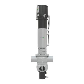
APV_D4_D4SL_GB-3_022024.indd Mode of Operation 4.1. General terms fig. 4.1. D4 valve Due to its construction and mode of operation as well as to the use of high quality stainless steel and adequate seal materials, the D4 CU41 and D4 SL double seat mix proof valves are suited for applications control unit in the food and beverage industries as well as in pharmaceutical and chemical applications. -
Page 9: Valve In "Closed" Position
APV_D4_D4SL_GB-3_022024.indd Mode of Operation fig. 4.2. 4.2. Valve in "closed" position The lower and upper valve shaft are in closed position and safely separate the different liquids A and B. The leakage chamber L, which is situated between the two valve shafts, provides for a free and depressurized discharge to the bottom. -
Page 10: Control Units / Valve Position Indication
Proximity switch 24V DC, PNP, 11 mm DIA. (cable box): H16432 If the customer decides to use valve position indicators other than those listed above, SPX FLOW cannot assume any liability for the functionality of the valve. Double Seat Mix Proof Valve APV DELTA D4 / D4 SL Instruction Manual: GB - rev. -
Page 11: Cleaning
D4 valve: CIP spraying must generally be undertaken. CIP spraying does not produce pressure build-up in the leakage chamber. SPX FLOW recommends performing CIP-spraying in the closed valve position; however, it can also be done in the open valve position. -
Page 12: D4 Sl Valve: Cleaning Of Upper Area
APV_D4_D4SL_GB-3_022024.indd Cleaning fig. 6.5. 6.5. D4 SL valve: Cleaning of upper area (fig. 6.5.) The upper valve shaft is lifted via connection (2), as shown in fig. 4.1.1 on page 8. Through the lifting of the upper valve shaft, the cleaning fluid flushes over the upper seat seal and the upper valve seat into the leakage chamber and cleans this area. -
Page 13: Installation And Commissioning
APV_D4_D4SL_GB-3_022024.indd Installation and Commissioning The valve must be installed in vertical position to ensure that fluids can drain off freely from the valve housing and the leakage chamber. Caution! Leakages and fluid losses from seat lifting and CIP- spraying must be safely collected and drained! The valve housing can be welded directly into the pipeline (completely removable valve insert). -
Page 14: Dimensions / Weights
APV_D4_D4SL_GB-3_022024.indd Dimensions / Weights 8.1. D4 Valve CU4 control unit housing configuration D41 1-8 D41 1-7 D41 1-6 install. dimen. min. in weights Dimensions in mm in kg Ø Da Ø Di with CU 14,9 15,0 16,6 142,5 25,5 142,5 1020 25,9 1006... -
Page 15: D4 Sl Valve
APV_D4_D4SL_GB-3_022024.indd Dimensions / Weights 8.2. D4 SL Valve CU4 control unit housing configuration D41 1-8 D41 1-7 D41 1-6 install. dimen. min. in weights Dimensions in mm in kg Ø Da Ø Di with CU 15,5 15,6 17,2 142,5 1010 25,5 142,5 1060... -
Page 16: Technical Data
APV_D4_D4SL_GB-3_022024.indd Technical Data 9.1. General data Product-wetted parts 1.4404, 316L (DIN EN 10088) Other parts 1.4301,304 (DIN EN 10088) Seals DN40–100/1,5"-4" standard EPDM DN40–100/1,5"-4" options HNBR, FPM DN125-150, 6" standard EPDM/PTFE compound DN125-150, 6" options HNBR/PTFE compound FPM/PTFE compound Max. line pressure 10 bar Max. -
Page 17: Kvs Values
APV_D4_D4SL_GB-3_022024.indd Technical Data 9.3. Kvs values in m³/hr D4 SL D4 SL D4 SL D4 SL Inch 1,5" 2" 2,5" 3" 4" 6" 9.4. Air consumption / Switching times Air consumption at Switching times in seconds 5 bar D4 Valve at 5 bar / CU41 Actuator NL/stroke... -
Page 18: Valve Stroke / Opening Cross Section
APV_D4_D4SL_GB-3_022024.indd Technical Data 9.5. Valve stroke / Opening cross section valve valve open closed D4 SL Valve: Dimensions in mm D4 Valve: Dimensions in mm stroke H1 stroke H2 stroke H1 stroke H2 upper shaft lower shaft upper shaft lower shaft Inch Inch 1,5"... -
Page 19: 10. Maintenance
26 assembly tool for seat seals, see page 27 2 long M8 hex screws for safe removal of valve insert For valve maintenance SPX FLOW offers complete seal kits (see spare parts lists). Caution! The use of seal materials being compatible with the product, application and CIP liquids must be ensured. -
Page 20: Service Instructions
APV_D4_D4SL_GB-3_022024.indd Service Instructions The item numbers refer to the spare parts drawings D4 1,5"-4", DN40-100 RN 500.047.01 D4 6", DN125-150 RN 500.047.03 D4 SL 1,5"-4", DN40-100 RN 501.047.01 fig. 11.1. D4 SL 6", DN125-150 RN 501.047.03 For the Disassembly/Assembly tools, see chapter 13. 11.1. - Page 21 APV_D4_D4SL_GB-3_022024.indd Service Instructions For the Disassembly/Assembly tools, see chapter 13. fig. 11.2. 11.2. Removal of product-wetted parts operating cam lower shaft 1. Remove the operating cam from the guide rod (7). 2. In order to take off the adapter, remove the 4 screws. 3.
-
Page 22: Installation Of Product-Wetted Seals And Assembly Of The Valve
APV_D4_D4SL_GB-3_022024.indd Service Instructions For the Disassembly/Assembly tools, see chapter 13. fig. 11.3. 11.3. Installation of product-wetted seals and assembly of the valve operating cam lower shaft Note! Make sure that all seals and bearing surfaces in the product area are slightly greased before their installation. -
Page 23: Installation Of The Valve Insert
APV_D4_D4SL_GB-3_022024.indd Service Instructions fig. 11.4. 11.4. Installation of the valve insert 1. Carefully place the valve insert in the valve housing (1) until the screw stops. 2. Remove the jacking screw and carefully press the valve insert into the housing (1). 3. -
Page 24: 12. Maintenance Of Actuator
APV_D4_D4SL_GB-3_022024.indd 12. Maintenance of Actuator The item numbers refer to the spare parts drawings fig. 12.: D4 Valve actuator D4 1,5"-4", DN40-100 RN 500.047.01 D4 6", DN125-150 RN 500.047.03 D4 SL 1,5"-4", DN40-100 RN 501.047.01 D4 SL 6", DN125-150 RN 501.047.03 12.1 Removing the actuator screws 1. -
Page 25: 13. Assembly Instructions And Tools For Seals
APV_D4_D4SL_GB-3_022024.indd 13. Assembly Instructions and Tools for Seals 13.1. Lower shaft seal Assembly tool (H171889) For the simple assembly of the lower shaft seal (11), the assembly/ disasssembly tool (H171889) and the assembly stick (H338450) can be used. These tools are especially recommended for valves assembly mandril of small series (DN40-65, 1,5”-3”) as access to the lower shaft seal from the top is impossible as a result of the narrow seat. -
Page 26: Middle Seal
APV_D4_D4SL_GB-3_022024.indd 13. Assembly Instructions and Tools for Seals 13.2. Middle seal The assembly tool consists of: thrust ring ring with venting tip thrust ring housing threaded bolt ring Installation of the middle seal in the valve shaft 1. Insert the valve shaft into the housing making sure that the seal groove is in the housing. -
Page 27: Seat Seals
APV_D4_D4SL_GB-3_022024.indd 13. Assembly Instructions and Tools for Seals 13.3. Seat seals Attention! Shoulders of the seat seals seal profile must be placed evenly seal lip in the seal groove. upper valve shaft seal foot lower shoulder valve shaft Provide the seal shoulder with a 3.1. -
Page 28: 14. Trouble Shooting
APV_D4_D4SL_GB-3_022024.indd 14. Trouble Shooting Failure Valve position Required seal replacement closed open Leakage at upper housing flange or upper shaft seal (11) yoke Leakage from the inside of the lower seat seals (10) valve shaft Leakage from the inside of the lower middle seal (9) valve shaft Leakage at the outside of the lower... - Page 71 F: (+48) 52 525 99 09 E: wcb@spxflow.com SPX FLOW reserves the right to incorporate the latest design and material changes without notice or obligation. Design features, materials of construction and dimensional data, as described in this manual, are provided for your information only and should not be relied upon unless confirmed in writing.
Need help?
Do you have a question about the APV D4 and is the answer not in the manual?
Questions and answers