Table of Contents
Advertisement
Quick Links
Advertisement
Table of Contents

Related Manuals for SPX FLOW APV CU41-S


Summary of Contents for SPX FLOW APV CU41-S
- Page 1 I N S T R U C T I O N M A N U A L APV CU4 AS-interface C O N T R O L U N I T F O R M N O . : H 3 2 6 4 0 6 R E V I S I O N : U K - 5 R E A D A N D U N D E R S TA N D T H I S M A N U A L P R I O R TO O P E R AT I N G O R S E RV I C I N G T H I S P R O D U C T.
-
Page 3: Table Of Contents
APV_CU4 AS-i_UK-5_072018.indd Content Page Abbreviations and Definitions Safety Instructions 2.1. Sentinels 2.2. Intended Use 2.3. General Regulations for Careful Handling 2.4. Welding instructions 2.5. Persons 2.6. Warranty Important Safety Instructions for AS-interface networks General Terms 3.1. Purpose of use 3.2. Design of CU4 AS-interface 3.3. -
Page 4: Abbreviations And Definitions
APV_CU4 AS-i_UK-5_072018.indd Abbreviations and Definitions Exhaust Air American Wire Gauge Communauté Européenne Control Unit Digital Input Digital Output EMC Electromagnetic Compatibility European Union Ground International Protection Luminous Diode Pneumatic Air Connection NOT element NEMA National Electrical Manufacturers Association Supply Air Connection PWM Pulse-Width Modulation Pneumatic Air Connection Safety Instructions 2.1. -
Page 5: Intended Use
The CU4 control unit is only intended for use as described in chapter 3.1. Use beyond that described in chapter 3.1. is not according to the regulations and SPX FLOW shall not be held responsible for any damage resulting from this non-observance. -
Page 6: Welding Instructions
APV_CU4 AS-i_UK-5_072018.indd Safety Instructions 2.4. Welding instructions It is generally recommended to avoid welding work in process installations in which control units are installed and connected. If welding is nonetheless required, earthing of the electrical devices in the welding area is a necessity. 2.5. -
Page 7: General Terms
APV_CU4 AS-i_UK-5_072018.indd General Terms 3.1. Purpose of use The CU4 AS-interface Control Unit was developed for the control of process valves used in the food and related industries. The CU4 control unit operates as interface between process control fig. 3.2. and process valve and controls the electric and pneumatic signals. - Page 8 APV_CU4 AS-i_UK-5_072018.indd General Terms 3.3. Function of the individual components The installation of the control unit is undertaken by special adapters which are available for the different valves types, see chapter 5. Adapter. The snap connectors for supply air and pneumatic air to the individual cylinders at the valves are located at the outside of the control unit.
-
Page 9: Function Of The Individual Components
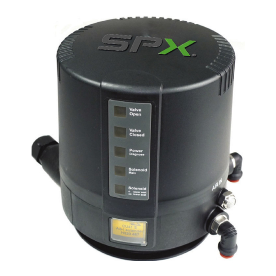
APV_CU4 AS-i_UK-5_072018.indd General Terms 3.3. Function of the individual components The luminous diodes are located on the front side of the electronic module. Their signals are visibly indicated to the outside by an optical window in the cover of the control unit. Beside the open and closed valve position, the existence of the operating voltage as well as different diagnostic information are indicated. -
Page 10: Mechanics And Pneumatics
APV_CU4 AS-i_UK-5_072018.indd Mechanics and Pneumatics 4.1. Air connection for valves with turning actuator 4.1.1. Function CU41-T-AS-i design for valve with turning actuator, e.g. butterfly valves P air supply with integrated particle filter Y1 bore to transfer control air to turning actuator AIR IN A1 exhaust air with exhaust silencer 4.2. Air connections for single seat and double seat mix proof valves 4.2.1. Function CU41-S-AS-i / CU41-M-AS-i / CU41-D4 design for seat valves and double seat mix proof valves without seat lift P ir supply with integrated particle filter Y1 control air connection for main actuator... -
Page 11: Pressure Relief Valve
APV_CU4 AS-i_UK-5_072018.indd Mechanics and Pneumatics 4.3. Pressure relief valve The base of the control unit is equipped with a pressure relief valve which prevents an inadmissible pressure build-up in the inner control unit. If required, the pressure relief vents into the clearance between the base and the adapter of the control unit. -
Page 12: Functional Description - Block Diagrams
APV_CU4 AS-i_UK-5_072018.indd Mechanics and Pneumatics 4.4 Functional description - block diagrams 4.4.1 CU41 AS-interface AS-i-Bus + The picture shows a standard NC (spring to closed) valve. AS-i-Bus - If NO (spring to open) valve is used, the sensor 5 VDC wiring can be different. Sensor 1 5 VDC Sensor 2 Normal Feedback Reverse Sensor 1 (“Valve closed”) Sensor 2 (“Valve open”) Solenoid valve Throttle valves... - Page 13 APV_CU4 AS-i_UK-5_072018.indd Mechanics and Pneumatics 4.4.2 CU41N – AS-interface Functional description - block diagram AS-i-Bus + The picture shows a standard NC (spring to closed) valve. AS-i-Bus - If NO (spring to open) valve is used, the sensor 5 VDC wiring can be different. Sensor 1 5 VDC Sensor 2 Normal Feedback Reverse Sensor 1 (“Valve closed”) Sensor 2 Pressure (“Valve open”) reducing valve...
- Page 14 APV_CU4 AS-i_UK-5_072018.indd Mechanics and Pneumatics 4.4.3. CU41-D4 AS-interface for D4 double seat mix proof valve Functional description - block diagram AS-i-Bus + AS-i-Bus - The picture shows a standard NC (spring to closed) valve. 5 VDC Sensor 1 5 VDC Sensor 2 Normal Feedback Reverse M1 - magnet upper shaft M2 - magnet lower shaft Sensor 2 “Valve open”...
- Page 15 APV_CU4 AS-i_UK-5_072018.indd Mechanics and Pneumatics 4.4.4 CU43 AS-interface for DE3, DA3+ double seat mix proof valves Functional description - block diagram AS-i-Bus + AS-i-Bus - The picture shows a standard NC 5 VDC (spring to closed) valve. Sensor 1 5 VDC Sensor 2 Normal Feedback Reverse Sensor 1 (“Valve closed”) Sensor 2 (“Valve open”) A/ Exhaust sol. 1 sol. 2 A/ Exhaust sol.
- Page 16 APV_CU4 AS-i_UK-5_072018.indd Mechanics and Pneumatics 4.4.5. CU43-D4 AS-interface für DA4 / D4 SL double seat mix proof valves Functional description - block diagram AS-i-Bus + AS-i-Bus - 5 VDC The picture shows a standard NC Sensor 1 (spring to closed) valve. 5 VDC Sensor 2 Normal Feedback Reverse M1 - magnet upper shaft M2 - magnet lower shaft Sensor 3 “Valve closed”...
-
Page 17: Technical Data / Standards
APV_CU4 AS-i_UK-5_072018.indd Mechanics and Pneumatics 4.5. Technical Data / Standards Material: PA6.6 Ambient temperature: -20°C to +70°C EU: EMC 2014/30/EU (89/336/EEC) Standards and environmental audits: Protection class IP 67 EN60529/ complies with NEMA 6 EMC interference resistance EN61000-6-2 EMC emitted interference EN61000-6-4 Vibration/oscillation EN60068-2-6 Safety of machinery DIN EN ISO 13849-1 Air connection: 6 mm / ¼"... -
Page 18: Solenoid Valves
APV_CU4 AS-i_UK-5_072018.indd Mechanics and Pneumatics 4.6. Solenoid valves In the base of the control unit max. 3 solenoid valves are installed. The 3/2-way solenoid valves are connected with the electronic module by moulded cables and plug connectors. Control: effected by pwm-signal Lever: rotary switch at valve 4.7. -
Page 19: Adapter
APV_CU4 AS-i_UK-5_072018.indd Adapter Adapter for different process valves 5.1. Valves with turning actuator, e.g. butterfly valves 5.2. Single seat valves 5.3. Double seat mix proof valves DE3, DA3+ 5.4 Double seat mix proof valves D4, D4 SL, DA4 Control Unit CU4 AS-interface Instruction manual: UK - rev. 5... -
Page 20: Electronic Module
5 VDC white hall Sensor 2 sensor black Electronic module Normal with sensors for Feedback SPX FLOW APV / WCB D4 valves Reverse CU4 AS-interface Spec. V3.01 Extended adress mode max. 62 slaves NTERFACE AS-interface Control Unit CU4 AS-interface... -
Page 21: Functional Description Of Connections
APV_CU4 AS-i_UK-5_072018.indd Electronic module 6.1.1 Switch-over of feedback signals The signals to the control can be switched over via the bridge between the terminals 10, 11 and 12. If a bridge is located between the terminals 10 and 11 (normal), the signal is transferred from sensor 1 (closed valve position) to input DI0 of the control. The signal of sensor 2 (open valve position) is sent to input DI1. -
Page 22: Use Of Data Bits
APV_CU4 AS-i_UK-5_072018.indd Electronic module 6.3. Use of data bits Communication data The use of the data bits shall be drawn from the following table: Data bit Info Connection Level main valve Low (no electric current) (output) High (current) upper seat lifting (optional) Low (no electric current) (output) High (current) lower seat lifting (optional) Low (no electric current) output) High (current) free (output) Feedback bridge Data bit normal (10 11 12) reverse (10 11 12) valve position, sensor 1 valve position, sensor 2 (closed valve position) (open valve position) -
Page 23: Technical Data
APV_CU4 AS-i_UK-5_072018.indd Electronic module 6.4. Technical Data AS-interface profile: S-7.A.*.E (S-7.F.F.F as option) Extended address range: is supported Serial communication mode: Inverse polarity protection: exists Indication "Power": LED3 (green) Indication "Fault": LED3 (red) AS-interface voltage range: 26,5…31,6 V Max. power input: <= 150 mA Input delay time: < 1 s AS-interface specification: V3.0 Supply of solenoid valves: PWM signal from electronic module Short-circuit protection: Excess voltage protection: 100 mA Induction protection: Status indication of outputs: LED on board Response time of watchdog: --- (watchdog not activated) Short-circuit or excess voltage of actuator supply or cable... -
Page 24: Connections
APV_CU4 AS-i_UK-5_072018.indd Electronic module 6.5. Connections Sensors to detect the valve positions: Internal sensors: Hall effect sensors, APV valves: H320385 APV / WCB D4 valves: H337014 UB 4,75-5,25 VDC operating distance according to SPX FLOW specification External sensors: Inductive proximity switches: H208844 UB 4,75-5,25 VDC operating distance according to SPX FLOW specification Control Unit CU4 AS-interface... -
Page 25: Led Indication
APV_CU4 AS-i_UK-5_072018.indd Electronic module 6.6. LED indication External luminous displays Valve Open colour: green, permanent light Valve in open position Valve Closed colour: orange, permanent light Valve in closed position Valve Open colour: green, flashing Bridge missing at terminals 10, 11, 12 Valve Closed colour: orange, flashing operating voltage at module -... -
Page 26: Feedback Unit
Instead of the internal Hall effect sensors, also 2 external proximity Feedback unit for switches can be connected to the CU4 DC, e.g. for the valve SPX FLOW APV / WCB D4 valves position indication at double seat valves. Proximity switch: H208844... -
Page 27: Cu Assembly And Startup
APV_CU4 AS-i_UK-5_072018.indd CU Assembly and Startup 8.1. Valves with turning actuator, e.g. butterfly valves CU cover CU base with electronic module, sensor tower and solenoid valves clamp ring fastening screws O-ring adapter operating cam with permanent magnet actuator Caution! The permanent magnet is made of fragile material and must be protected against mechanical load. - Page 28 APV_CU4 AS-i_UK-5_072018.indd CU Assembly and Startup 8.1.1 Pneumatic connection Supply air: CAUTION! Shut off the compressed air supply before connecting the air hose! See that the air hose is professionally cut to length. Use a hose cutter for this purpose. Pneumatic air for valve actuator: For the assembly of the control unit on the turning actuator with integrated air transfer, air hosing between the control unit and the actuator is not necessary.
- Page 29 APV_CU4 AS-i_UK-5_072018.indd CU Assembly and Startup 8.1.3 Startup After proper assembly and installation of the control unit, startup can be undertaken as described below: lever 1. Switch on the air supply. 2. Switch on the voltage supply. 3. Check the solenoid valves by turning the lever on the upper side of the valve by 90°.
-
Page 30: Single Seat Valves
APV_CU4 AS-i_UK-5_072018.indd CU Assembly and Startup 8.2. Single seat valves CU cover CU base with electronic module, sensor tower and solenoid valves clamp ring fastening screws adapter operating cam with permanent magnet actuator Caution! The permanent magnet is made of fragile material and must be protected against mechanical load. - Page 31 APV_CU4 AS-i_UK-5_072018.indd CU Assembly and Startup 8.2.1 Pneumatic connection Supply air: CAUTION! Shut off the compressed air supply before connecting the air hose! See that the air hose is professionally cut to length. Use a hose cutter for this purpose. Pneumatic air for valve actuator: Connect the pneumatic air connection Y1 with the valve actuator.
- Page 32 APV_CU4 AS-i_UK-5_072018.indd CU Assembly and Startup 8.2.3 Startup After proper assembly and installation of the control unit, startup can be undertaken as described below: lever 1. Switch on the air supply. 2. Switch on the voltage supply. 3. Check the solenoid valves by turning the lever on the upper side of the valve by 90°.
-
Page 33: Double Seat Mix Proof Valves De3, Da3
APV_CU4 AS-i_UK-5_072018.indd CU Assembly and Startup 8.3. Double seat mix proof valves DE3, DA3+ CU cover CU41/CU43 clamp ring fastening screws adapter feedback 1 for seat lift cylinder closed valve position external air actuator proximity switches feedback 2 for open spring cylinder valve position Assembly of the control unit on the valve 1. Assembly of the adapter on the double seat valve. Fasten with 4 screws. - Page 34 APV_CU4 AS-i_UK-5_072018.indd CU Assembly and Startup 8.3.1 Pneumatic connection Supply air: CAUTION! Shut off the compressed air supply before connecting the air hose! See that the air hose is professionally cut to length. Use a hose cutter for this purpose. Pneumatic air to valve actuator: Connect pneumatic air connection Y1 with the valve actuator.
- Page 35 APV_CU4 AS-i_UK-5_072018.indd CU Assembly and Startup 8.3.4 Startup lever After proper assembly and installation of the control unit, startup can be undertaken as described below: 1. Switch on the air supply. 2. Switch on the voltage supply. 3. Check the solenoid valves by turning the lever on the upper side of the valve by 90°.
-
Page 36: Double Seat Mix Proof Valves D4, D4 Sl, Da4
APV_CU4 AS-i_UK-5_072018.indd CU Assembly and Startup 8.4. Double seat mix proof valves D4, D4 SL, DA4 CU cover CU41/CU43 operating cam with magnet M1 screws clamp ring adapter operating cam with magnet M2 actuator Assembly of the control unit on the valve 1. Assemble the magnet M2 on the upper shaft under the stop screw. 2. - Page 37 APV_CU4 AS-i_UK-5_072018.indd CU Assembly and Startup 8.4.1 Pneumatic connection Supply air: Caution! Shut off the compressed air supply before connecting the air hose! Make sure that the air hose is professionally cut to length. Use a hose cutter for this purpose. Pneumatic air to valve actuator: Connect pneumatic air connection Y1 with the valve actuator.
- Page 38 CU Assembly and Startup 8.4.3 Connection of external proximity switches lever The electric connection of the proximity switches specified by SPX FLOW is undertaken according to the terminal layout described in chapter 6.1. The mechanic assembly of the proximity switches is carried out at the actuator of the corresponding double seat valves.
-
Page 39: Replacement Of A Cu3 Control Unit
APV_CU4 AS-i_UK-5_072018.indd CU Assembly and Startup 8.5. Replacement of a CU3 control unit All CU41 variants can substitute a CU3 control unit without changing the signal routing. When replacing the CU3, the larger dimensions of the CU4 control unit must, however, be considered. If a CU43 is to replace a CU33 control unit, the change of the seat lifting signals must be observed. -
Page 40: Accessories And Tools
APV_CU4 AS-i_UK-5_072018.indd Accessories and Tools Assembly/disassembly - adapter on valve actuator: • hexagon socket wrench 6 mm • screwdriver 4mm Assembly/disassembly – CU on adapter: • hexagon socket wrench 3 mm Assembly/disassembly – electronic module: • torx wrench TX20 • screwdriver 3.5 mm Assembly/disassembly – feedback unit: • torx wrench TX15 Assembly/disassembly – electronic modules: • torx wrench TX20 Assembly/disassembly – air connections: • jaw wrench M13 Assembly/disassembly – pressure relief valve: • torx wrench TX10 Loctite semi-solid jaw wrench torx wrench hexagon socket wrench screwdriver Control Unit CU4 AS-interface Instruction manual: UK - rev. -
Page 41: 10. Service
Open the cover. Feedback unit for Release the cable for the Hall effect sensors from the terminal SPX FLOW APV / WCB D4 valves strip, terminals 3-8. Release the clamp ring and lift the CU4 from the adapter. + Remove the 4 screws (9) TX15 at the lower side of the CU base (1). -
Page 42: 11. Trouble Shooting
APV_CU4 AS-i_UK-5_072018.indd 11. Trouble Shooting General Failures Remedy Valve position is not indicated. Re-adjust Hall sensors. Check fastening of magnetic operating cam. Check cabeling of the Hall sensors to the electronic module. Feedback via proximity Check positioning of proximity switches is missing switches. - Page 43 APV_CU4 AS-i_UK-5_072018.indd 11. Trouble Shooting Failure Remedy Control Unit CU41 installed on Single seat and Double seat valves Valve position movement is Check if the right control unit is missing with actuated solenoid installed. Check label in type valve. window of control unit: CU41-S-AS-interface (1 solenoid) CU41-M-AS-interface CU41-D4-AS-interface Check valve movement with lever at solenoid valve.
-
Page 44: 12. Spare Parts Lists
APV_CU4 AS-i_UK-5_072018.indd 12. Spare Parts Lists The reference numbers of spare parts for the different control unit designs and adapters are included in the attached spare parts drawings with corresponding lists. CU4 AS-interface RN 01.044.5 CU4 adapter RN 01.044.3 When you place an order for spare parts, please indicate the following data: - number of parts required - reference number... - Page 45 Datum: 05/10 06/10 09/10 07/18 Name: D.Schulz D.Schulz D.Schulz C.Keil Geprüft: Ersatzteilliste: spare parts list SPX FLOW Germany Blatt CU4 AS-interface RN 01.044.5...
- Page 60 F: (+48) 52 525 99 09 SPX FLOW reserves the right to incorporate the latest design and material changes without notice or obligation. Design features, materials of construction and dimensional data, as described in this manual, are provided for your information only and should not be relied upon unless confirmed in writing.
Need help?
Do you have a question about the APV CU41-S and is the answer not in the manual?
Questions and answers