
Related Manuals for Vertiv NetSure 731 C62 Series


Summary of Contents for Vertiv NetSure 731 C62 Series
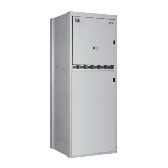
- Page 1 NetSure™ 731 C62 Series Power System User Manual BOM Number: 31014252 Model Number: R48-3000e3, M530S...
- Page 2 The products covered by this instruction manual are manufactured and/or sold by Vertiv. This document is the property of Vertiv and contains confidential and proprietary information owned by Vertiv. Any copying, use or disclosure of it without the written permission of Vertiv is strictly prohibited.
-
Page 3: Table Of Contents
Vertiv™ NetSure™ 731 C62 Series Power System User Manual TABLE OF CONTENTS Admonishments Used in this Document ....................v Important Safety Instructions ........................ vi Static Warning ............................ix 1 Overview ............................1 1.1 Model Description ............................1 1.2 Composition and Configuration ........................1 1.3 Features ................................ - Page 4 Vertiv™ NetSure™ 731 C62 Series Power System User Manual 4.7 Setting System Parameters ........................... 12 4.7.1 Alarm Settings........................... 12 4.7.2 Battery Settings ..........................16 4.7.3 AC Settings ............................21 4.7.4 DC Settings ............................22 4.7.5 DC Rectifier Settings ......................... 22 4.7.6 Solar Converter Settings ........................
-
Page 5: Admonishments Used In This Document
Vertiv™ NetSure™ 731 C62 Series Power System User Manual Admonishments Used in this Document DANGER! Warns of a hazard the reader will be exposed to that will likely result in death or serious injury if not avoided. (ANSI, OSHA) WARNING! Warns of a potential hazard the reader may be exposed to that could result in death or serious injury if not avoided. -
Page 6: Important Safety Instructions
Vertiv™ NetSure™ 731 C62 Series Power System User Manual Important Safety Instructions Safety Admonishments Definitions Definitions of the safety admonishments used in this document are listed under “Admonishments Used in this Document” on page v. General Safety DANGER! YOU MUST FOLLOW APPROVED SAFETY PROCEDURES. - Page 7 Vertiv™ NetSure™ 731 C62 Series Power System User Manual Battery Refer to the battery manufacturer documentation for specific battery safety instructions. The following are general guidelines. WARNING! Correct polarity must be observed when connecting battery leads. WARNING! Special safety precautions are required for procedures involving handling, installing, and servicing batteries.
- Page 8 Vertiv™ NetSure™ 731 C62 Series Power System User Manual Personal Protective Equipment (PPE) DANGER! ARC FLASH AND SHOCK HAZARD. Appropriate PPE and tools required when working on this equipment. An appropriate flash protection boundary analysis should be done to determine the “hazard/risk” category, and to select proper PPE.
-
Page 9: Static Warning
Vertiv™ NetSure™ 731 C62 Series Power System User Manual Static Warning This equipment contains static sensitive components. The warnings listed below must be observed to prevent damage to these components. Disregarding any of these warnings may result in personal injury or damage to the equipment. - Page 10 Vertiv™ NetSure™ 731 C62 Series Power System User Manual This page intentionally left blank.
-
Page 11: Overview
Vertiv™ NetSure™ 731 C62 Series Power System User Manual 1 Overview This chapter introduces model description, composition and configuration, features, operating principle and functions of the power system. The ‘power system’ in this manual refers to the NetSure 731 C62-X4 and NetSure 731 C62-XF power system. -
Page 12: Features
Vertiv™ NetSure™ 731 C62 Series Power System User Manual Configuration The configuration of the power system is listed in Table 1.1. Table 1.1 Power system configuration Configuration Item NetSure 731 C62-X4 NetSure 731 C62-XF Model: R48-3000e3 Model: R48-3000e3 Rectifier Standard configuration: 6 pieces... -
Page 13: Operating Principle
Vertiv™ NetSure™ 731 C62 Series Power System User Manual • The M530S controller can save 10 sets of battery test data records • The power system has network design. Providing multiple communication ports (such as RS485, USB, Ethernet and CAN), which enables flexible networking and remote monitoring and unmanning •... - Page 14 Vertiv™ NetSure™ 731 C62 Series Power System User Manual Rectifier 5m ~ 10m AC Input AC input Rectifier - 48V output II/C Rectifier Battery Battery Monitoring string Controller Cotroller 1, 2 module RS232 Note: Classes I, II, III are IEC standard, classes B,...
-
Page 15: Llvd And Blvd
Vertiv™ NetSure™ 731 C62 Series Power System User Manual The Class I/B SPD should be purchased and mounted by the user. If condition permits, it is recommended that the cable length between the Class I/B SPD and the power system meet the following rules: if a voltage limiting type SPD is used, then the cable length should be longer or equal than 5m;... -
Page 16: Earthing Design
Vertiv™ NetSure™ 731 C62 Series Power System User Manual • Battery current detection. • DC output overvoltage, undervoltage alarm functions. See Table 1.3 for the functions of the DC input and output interfaces of the power system. Table 1.3 Functions of DC input and output interface functions... -
Page 17: Installation Instruction
The equipment should be unpacked and inspected after it arrives at the installation site. The inspection shall be done by representatives of both the user and Vertiv Tech Co., Ltd. To inspect the equipment, you should open the packing case, take out the packing list and check against the packing list that the equipment is correct and complete. -
Page 18: Mechanical Installation
Vertiv™ NetSure™ 731 C62 Series Power System User Manual Select the battery cable CSA according to Table 2.2. Select the load cable CSA according to Table 2.3. Table 2.2 Battery cable CSA selection Battery fuse Max. battery Max. cable length (allowable Max. -
Page 19: Installing Rectifiers
Vertiv™ NetSure™ 731 C62 Series Power System User Manual Figure 2.1 Equipment room layout 2. Install expansion bolts By referring to Figure 2.2, mark the central points of the installation holes on the floor. Use the electric drill (aiguille: Φ14) to dig holes (depth: 70mm) at the marked points. Clean the drilled hole of dust. Put the expansion bolt into the hole and knock it with a hammer till it is totally in. -
Page 20: Electrical Installation
Vertiv™ NetSure™ 731 C62 Series Power System User Manual Figure 2.3 Handle of the rectifier Fixing screw Handle 2. Put the rectifiers in the slot. Push the rectifier completely into the cabinet. Close the handle and tighten the fixing screw to lock the rectifiers onto the cabinet. - Page 21 Vertiv™ NetSure™ 731 C62 Series Power System User Manual Figure 2.6 Connection terminals (back view) Grounding terminal Neutral line busbar Connecting AC cables 1. Connect the AC input phase cables to the AC input MCB, as shown in Figure 2.7. The figure shows the two routes of mains input MCB configuration.
- Page 22 Vertiv™ NetSure™ 731 C62 Series Power System User Manual Figure 2.8. The specifications of the positive busbar connection screw are 8mm and 6mm. Please connect the load ¢ ¢ cable according to the priority load and non-priority load labels.
- Page 23 Vertiv™ NetSure™ 731 C62 Series Power System User Manual Figure 2.8 Diagram of the load cable Battery fuse Priority load MCB Non-priority load MCB Controller Connecting battery cables NOTE! 1. The batteries may have dangerous current. Before connecting battery cables, make sure that the battery fuses at the system side and the battery MCBs at the battery side are switched off.
-
Page 24: Connecting Signal Cables
Vertiv™ NetSure™ 731 C62 Series Power System User Manual 3. The wiring path of battery cable configured in NetSure 731 C62 is shown in Figure 2.9. Figure 2.9 Battery cable wiring path of NetSure 731 C62-X2 2.4.2 Connecting Signal Cables All the signal cables are connected to controller. - Page 25 Vertiv™ NetSure™ 731 C62 Series Power System User Manual Figure 2.10 Interfaces of the controller Table 2.4 Interface functions Silkscreen Definition Function 3, 6, 9 J6, J7 2, 5, 8 5 pairs of dry contact alarm output 1, 4, 7...
- Page 26 Vertiv™ NetSure™ 731 C62 Series Power System User Manual Lead the cable ties through the fixing holes at the top of the cabinet. Use the cable ties to fix the modem on the top of the cabinet, as shown in Figure 2.11.
-
Page 27: Testing
Vertiv™ NetSure™ 731 C62 Series Power System User Manual 3 Testing This chapter introduces the testing procedures after installation. The corresponding safety rules shall be adhered to in the test. 3.1 Installation Check and Startup Before the test, inform the chief manufacturer representative. Only trained electrical engineers shall maintain and operate the power system. - Page 28 Vertiv™ NetSure™ 731 C62 Series Power System User Manual output voltages...
-
Page 29: Basic Settings
Vertiv™ NetSure™ 731 C62 Series Power System User Manual 3.2 Basic Settings When the power system is put into service for the first time, the parameters of controller must be set based on the actual system configuration, such as battery string number, capacity, user’s charge current limit and other functional requirements. -
Page 30: Final Steps
Vertiv™ NetSure™ 731 C62 Series Power System User Manual Check item Comments The system model is NetSure 731 C62: 48V/300 The controller should display the correct AC voltage The controller should be able to display the DC voltage. The difference between the displayed voltage and that measured ... -
Page 31: Use Of The Controller
Vertiv™ NetSure™ 731 C62 Series Power System User Manual 4 Use of The Controller This chapter briefly introduces the indicators and functional keys on the operation panel of the controller, and expounds the main screen contents, access method, system controlling, information querying and parameter setting. -
Page 32: System Information Screen
Vertiv™ NetSure™ 731 C62 Series Power System User Manual NOTE! The contents of the screens given in this manual are just examples. For different configurations, models and system states, the actual contents of the screens may be different from this manual. -
Page 33: Mainmenu Screen
Vertiv™ NetSure™ 731 C62 Series Power System User Manual 1. When inputting the password, press the ENT key to get into editing state, press ▲ or ▼ to move the cursor, and press ◄ or ► to modify numbers. After the input, press the ENT key to confirm. -
Page 34: Settings Screen
Vertiv™ NetSure™ 731 C62 Series Power System User Manual 4.2.5 Settings Screen Displayed in many screens, the Settings screen is a sub-menu of the main menu. It is used to set all system parameters. The Settings screen has password protection function, only the correct password allows you to enter it. See Figure 4.7 for the Settings screen. -
Page 35: Energy Saving Screen
Vertiv™ NetSure™ 731 C62 Series Power System User Manual Figure 4.9 Maintenance screen Maintenance Maintenance Start: FC RectTrim: 53.5V 54.0V Batt: Reconnect RectLimit: 121% Load: Reconnect If some sampling values of the system enter the special range (for example, DC busbar in under-voltage state), the ‘Sys Mode’... -
Page 36: Querying System Main Information
Vertiv™ NetSure™ 731 C62 Series Power System User Manual Table 4.4 Fast setting range and default values Parameter Setting range Default Setting description 24V/100 24V/300 When the controller is shipped with the power system, the system type of the controller 24V/500 has been set according to the actual situation, and the user does not need to change it. -
Page 37: Querying Rectifier Information
Vertiv™ NetSure™ 731 C62 Series Power System User Manual Figure 4.14 Battery information screen Batt1: 0.0A Remain: 100% Batt2: 0.0A Remain: 100% ‘Batt 1’, ‘Batt 2’ and ‘Batt 3’ represent respectively the current that flowed through battery shunt 1, battery 2 and battery shunt 3. -
Page 38: Querying Alarms Information
Vertiv™ NetSure™ 731 C62 Series Power System User Manual Figure 4.17 Rectifier information screen Rect 1: Curr Limit: 110% AC Derated: ID: 01060700584 In Volt: 220V Temp Derated: Y Out Volt: 53.5V AC State: Out Curr: 38.5A DC State: ... - Page 39 Vertiv™ NetSure™ 731 C62 Series Power System User Manual Table 4.5 Active alarm of the controller Alarm type Alarm Description Rect AC Fails Rect Over Temp Rect Fault Rect Protect Reported by rectifiers Rectifier Rect Fan Fails Rect Derated Rect Not Respond...
-
Page 40: Querying History Alarm
Vertiv™ NetSure™ 731 C62 Series Power System User Manual Alarm type Alarm Description Load Fuse Alarm 6 Load failure caused by overload, short circuit, manual disconnect, or alarm circuit failure Load Fuse Alarm 7 Load failure caused by overload, short circuit, manual disconnect, or alarm circuit failure... -
Page 41: Maintenance
Vertiv™ NetSure™ 731 C62 Series Power System User Manual 3. At any History Alarm screen, press the ESC key repeatedly to return to the higher-level menu, and ultimately return to the first system information screen. 4.6 Maintenance NOTE! Be careful! BLVD operations may result in load power interruption. -
Page 42: Setting System Parameters
Vertiv™ NetSure™ 731 C62 Series Power System User Manual 4.7 Setting System Parameters The system parameters are divided into eight kinds, including alarm settings, battery settings, AC settings, DC settings, rectifier settings, system settings, communication settings and DCEM settings. Without any special needs, you only need to reset the battery group and battery capacity according to the system configuration and battery actual instance, and accept the factory settings for other parameter settings. - Page 43 Vertiv™ NetSure™ 731 C62 Series Power System User Manual Related Alarm Description Alarm level Related relay parameter The alarm name is user-defined, at most 10 letters. In this No alarm None system, eight DIs can be defined. Load failure caused by overload, short circuit, manual...
- Page 44 Vertiv™ NetSure™ 731 C62 Series Power System User Manual Related Alarm Description Alarm level Related relay parameter The DC output voltage is higher than the setting of DC output High-voltage DC Volt High Critical high-voltage alarm point alarm The DC output voltage is higher than the setting of DC output...
- Page 45 Vertiv™ NetSure™ 731 C62 Series Power System User Manual Related Alarm Description Alarm level Related relay parameter DC Converter Fan The fan of DC converter module is faulty Major None Fault DC Converter Over The DC converter module is over-voltage, higher than the limited...
-
Page 46: Battery Settings
Vertiv™ NetSure™ 731 C62 Series Power System User Manual 4.7.2 Battery Settings Battery parameters are important, because they are related to the life-span of battery. At the Settings screen (see Figure 4.7), press ▲ or ▼ to select the ‘Bat Settings’ menu, and press the ENT key to enter the Bat Settings screen shown in Figure 4.26. - Page 47 Vertiv™ NetSure™ 731 C62 Series Power System User Manual LVD parameters At the Bat Settings screen, press ▲ or ▼ to select the ‘LVD Setting’ menu, and press the ENT key to enter the LVD Setting screen shown in Figure 4.28.
- Page 48 Vertiv™ NetSure™ 731 C62 Series Power System User Manual The value description of the charge parameters is listed in Table 4.10. Table 4.10 Description of the charge parameter setting Parameter Range Factory setting Value description Float 53.5V The rectifier output voltage in FC state...
- Page 49 Vertiv™ NetSure™ 731 C62 Series Power System User Manual Figure 4.30 BC/FC switchover diagram FC time longer than 'Cyc Boost Period' Battery charge current bigger than 'To Boost Current' Battery capacity smaller than 'To Boost Cap' Charge current Constant BC...
- Page 50 Vertiv™ NetSure™ 731 C62 Series Power System User Manual Table 4.11 Description of the battery test parameter setting Parameter Range Factory setting Value description End Test -Volt 43.1V ~ 57.9V 45.2V The controller will stop the battery test and switch to FC state if the battery...
-
Page 51: Ac Settings
Vertiv™ NetSure™ 731 C62 Series Power System User Manual 2. Press ▲ or ▼ to select the parameter and press ◄ or ► to select the parameter value. Then press the ENT key to confirm. The value description of the temperature compensation parameters is listed in Table 4.12. -
Page 52: Dc Settings
Vertiv™ NetSure™ 731 C62 Series Power System User Manual 4.7.4 DC Settings At the Settings screen (see Figure 4.7), press ▲ or ▼ to select the ‘DC Settings’ menu, and press the ENT key to enter the screen shown in Figure 4.35. -
Page 53: Solar Converter Settings
Vertiv™ NetSure™ 731 C62 Series Power System User Manual Parameter Range Factory setting Value description The rectifier over-voltage alarm will be generated when the rectifier output HVSD 56V ~ 59V 58.0V voltage is higher than the setting value Default V 48V ~ 58V 53.5V... - Page 54 Vertiv™ NetSure™ 731 C62 Series Power System User Manual Figure 4.38 Settings screen upon user level ComDownLoad: N Ctrlmode: Save Lang: English System Type: Op2 PWD: ****** Op1 PWD: ****** Reset PWD: ComDownload: N Tzone: GMT+08: 00...
-
Page 55: Communication Settings
Vertiv™ NetSure™ 731 C62 Series Power System User Manual Parameter Range Factory setting Value description Reset Para Y, N Whether resetting the parameter to the default Op1 PWD The password can be six digits long at most. If it is shorter than six digits,... -
Page 56: Dg Control Settings
Vertiv™ NetSure™ 731 C62 Series Power System User Manual Factory Parameter Range Value description setting AC Power Grid, DG, Grid+DG Grid System power supply mode, ‘Grid’ by default Mode DG Cap 5.0KVA ~ 100.0KVA 12.5KVA Set it according to actual DG capacity Dry contact input of DG running state, users can set the DG state by referring to the ‘Ative’... -
Page 57: Dcem Settings
Vertiv™ NetSure™ 731 C62 Series Power System User Manual Factory Parameter Range Value description setting Y: The system will determine whether stop DG according to battery remainning capacity; BattCap En Y, N N: The system will not judge the battery capacity When the ‘BattCap En’... -
Page 58: Dc Converter Settings
Vertiv™ NetSure™ 731 C62 Series Power System User Manual Parameter Range Factory setting Value description -Sh3 Curr 10A ~ 1000A 100A Current of DCEM2 shunt3 -Sh3 Volt 10mV ~ 100mV 75mV Voltage of DCEM2 shunt3 -Sh4 Curr 10A ~ 1000A... - Page 59 Vertiv™ NetSure™ 731 C62 Series Power System User Manual Figure 4.46 User1 setting screen User Name: Other CMCC - Curr: 175A 100A LVDTime: 600min 300min - Volt: 25mV LVD Shunt: Shunt Coeff: User2 settings At the screen shown in Figure 4.45, press ▲ or ▼ to select the user parameter needs to be set, and press ENT key to enter the screen shown in Figure 4.47.
-
Page 60: Fan Settings
Vertiv™ NetSure™ 731 C62 Series Power System User Manual Factory Parameter Range Value description setting LVD Time 3min ~ 2880min 300min LVD time of User1 LVD Shunt Y, N Whether User1 has shunt Shunt Coeff-Curr 1A ~ 2000A 100A Shunt current coefficient of User1, used with voltage coefficient... -
Page 61: Energy Saving Settings
Vertiv™ NetSure™ 731 C62 Series Power System User Manual Factory Parameter Range Value description setting The fan is controlled according to the temperature of selected test Temp SRC Temp1, Temp2, Temp3 Temp2 object Fan Mode Exch, Force Exch Fan working mode MNG Settings Select ‘Y’... -
Page 62: Fast Settings
Vertiv™ NetSure™ 731 C62 Series Power System User Manual If the battery is configured and the load current has no instant shock, the system will operate in energy saving mode, that is, ‘Save Enable’ is set to ‘Y’. 3. Advantage •... - Page 63 Vertiv™ NetSure™ 731 C62 Series Power System User Manual Parameter Range Factory setting Value description The system type of the controller has been set according to the actual instance 48V/100 before the controller is delivered with power supply system. You do not need to 48V/300 change the value except that the controller needs to be replaced with a new one.
-
Page 65: Technical Parameters Of Rectifier
Vertiv™ NetSure™ 731 C62 Series Power System User Manual 5 Technical Parameters of Rectifier This chapter introduces the appearance and structure, functions and features, and technical parameters of the rectifier. 5.1 Appearance and Structure Front panel The front panel of the rectifier has three indictors, as shown in Figure 5.1. -
Page 66: Functions And Features
Vertiv™ NetSure™ 731 C62 Series Power System User Manual Rear panel There are AC input socket and DC output socket on the rear panel of the rectifier, as shown in Figure 5.2. Figure 5.2 Rear panel of the rectifier J1 J7... - Page 67 Vertiv™ NetSure™ 731 C62 Series Power System User Manual Figure 5.3 Relationship between output power and input power Output characteristics The relationship between output voltage and current is listed in Table 5.3. Table 5.3 Output characteristics Output power Output current...
- Page 68 Vertiv™ NetSure™ 731 C62 Series Power System User Manual Figure 5.4 Output power and temperature Output current limiting adjustment The maximum current of the rectifier can range from 10% to 120% of the full load through the controller programming. If the controller communication fails, the default rectifier current is 100% of the full load rated power. The full load rectifier is defined as the maximum available current (62.5A) in the output load range.
- Page 69 Vertiv™ NetSure™ 731 C62 Series Power System User Manual 2) Lock out at the second overvoltage (by default) When the output voltage reaches the software protection point, the rectifier will shutdown, and restart automatically after 5 seconds. If the overvoltage happens again within a set time (default: 5min. Configurable through controller), the rectifier will shut down and hold that state.
-
Page 70: Technical Parameters
Vertiv™ NetSure™ 731 C62 Series Power System User Manual Monitoring function There’s a built-in digital signal processor in the rectifier. The processor monitors and controls the rectifier operation, and communicates with the controller in real time through the CAN bus. Table 5.4 lists the exchanged commands and information between the rectifier and controller. -
Page 71: Troubleshooting
Vertiv™ NetSure™ 731 C62 Series Power System User Manual 6 Troubleshooting This chapter describes the handling of alarms, as well as the preventive maintenance of the power system during system daily operation. The maintenance personnel must have adequate knowledge about the power system. -
Page 72: Handling Rectifier Fault
Vertiv™ NetSure™ 731 C62 Series Power System User Manual Alarm Handling method 1. Check if the alarm is caused by mains failure, if yes, disconnect some loads to prolong the operation of the whole system. 2. Check the DC under-voltage value set through the controller. If the set value is inappropriate, correct it. -
Page 73: Handling Controller Fault
Vertiv™ NetSure™ 731 C62 Series Power System User Manual Controller Symptom Causes Handling method alarms due to: inlet or vent Ambient temperature too high or Decrease the ambient temperature or remove the heat the inlet too close to a heat... - Page 74 Vertiv™ NetSure™ 731 C62 Series Power System User Manual The steps for replacing the controller are as follows: 1. Unplug all alarm and communication terminals connected to the front end of the monitoring board. 2. Loosen the two fixing screws on the monitoring cover plate (see Figure 6.2), lift up the monitoring cover plate, remove the flat wire connecting the LCD and the monitoring panel (be careful not to pull hard;...
- Page 75 Vertiv™ NetSure™ 731 C62 Series Power System User Manual Terminal Definition Wiring instruction J3_1: RS485_1A RS485 communication terminal J3_2: RS485_1B (Downlink, connect the J3_3: RS485_2A background monitoring) J3_4: RS485_2B Display interface Display rectifier control DI input terminal Dry contact input...
-
Page 76: Handing Fuse Fault
Vertiv™ NetSure™ 731 C62 Series Power System User Manual 4. Remove the fixing screws of the PCB and replace the PCB. Note that the screwdriver should be prevented from touching the bare parts of the signal cables to prevent short circuit. -
Page 77: Technical Data
Level II Nominal output voltage -48Vdc Rated output voltage -53.5Vdc (When configure Vertiv outdoor cabinet, the rated voltage is -54V) Output DC voltage -43.2Vdc ~ -57.6Vdc DC output load current ≤ 400A/58V, battery charge current ≤ 66A/58A (configure R48-3000e3 rectifier) Max. - Page 78 Vertiv™ NetSure™ 731 C62 Series Power System User Manual Parameter category Parameter Description LLVD Default: -44.0Vdc ± 0.3Vdc, configurable through controller BLVD Default: -43.2Vdc ± 0.2Vdc, configurable through controller The rectifiers can work in parallel and share the current. The unbalance is...
-
Page 79: Engineering Diagram
Vertiv™ NetSure™ 731 C62 Series Power System User Manual Parameter category Parameter Description Acoustic noise ≤ 60dB (A) (When the ambient temperature is 25°C, with full load) At temperature of 25°C ± 5°C and relative humidity not bigger than 90%RH, Insulation resistance apply a test voltage of 500Vdc. -
Page 81: Parameter Setting Of The Controller
Vertiv™ NetSure™ 731 C62 Series Power System User Manual 9 Parameter Setting of The Controller This chapter gives the description of the controller parameter setting. The detailed information of the parameter setting and operating method are given in 4 Use of The Controller. - Page 82 Vertiv™ NetSure™ 731 C62 Series Power System User Manual Item Parameter Range Factory setting Value description The system in BC state will enter the FC state 0.002C Const Boost -Current 0.020C when the charge current decreases to the 0.020C ‘Const Boost Current’ value and after the ‘Const Boost Time’...
- Page 83 Vertiv™ NetSure™ 731 C62 Series Power System User Manual Item Parameter Range Factory setting Value description The controller will generate an alarm when Batt T L1 -40°C ~ +100°C 0°C the detected battery temperature is lower than Batt T L1...
- Page 84 Vertiv™ NetSure™ 731 C62 Series Power System User Manual Item Parameter Range Factory setting Value description Default output voltage when communication Default V 48V ~ 58V is interrupted. Must be lower than the ‘HVSD’ voltage Output voltage delta between solar converter MpptDelta 0.2V ~ 3.0V...
- Page 85 Vertiv™ NetSure™ 731 C62 Series Power System User Manual Item Parameter Range Factory setting Value description After the DG is started, and continuously 30min ~ 1440min running to the max. run time, the DG will be 2880min stopped After the DG is started, when meets the stop...
- Page 86 Vertiv™ NetSure™ 731 C62 Series Power System User Manual Item Parameter Range Factory setting Value description -Sh4 Curr 10A ~ 1000A 1000A Current of DCEM1 shunt4 -Sh4 Volt 10mV ~ 100mV 25mV Voltage of DCEM1 shunt4 DCEM2 -Sh1 Curr 10A ~ 1000A...
- Page 87 Vertiv™ NetSure™ 731 C62 Series Power System User Manual Item Parameter Range Factory setting Value description User4 settings CTCC, CUCC, User Name Other Name of User4, ‘Other’ by default CMCC, Other 3min ~ LVD Time 300min LVD time of User4...
-
Page 89: Menu Structure Of The Controller
Vertiv™ NetSure™ 731 C62 Series Power System User Manual 10 Menu Structure of The Controller Figure 10.1 Menu structure of the controller Main Menu Settings Energy Saving Status Maintenance Fast Settings Alarm Type Alarm Number Alarm Level Level Save Enable: Y... - Page 90 Vertiv™ NetSure™ 731 C62 Series Power System User Manual Figure 10.2 Menu structure of the battery parameters Bat. Settings Main System Information Sys Mode: Auto DC Volt Bat. Fuse: 2 DC Current Capacity: 500AH System Mode Alarm Bat. Shunt1: Y Bat.
-
Page 91: Wiring Diagram
Vertiv™ NetSure™ 731 C62 Series Power System User Manual 11 Wiring Diagram Figure 11.1 NetSure 731 C62 wiring diagram (1) Controller RS485 DC SPD unit BUS+ W07/W19 W06_3 Enclosure BUS- Top view module output negative bar DCSPD 25-- W19 Enclosure... - Page 92 Vertiv™ NetSure™ 731 C62 Series Power System User Manual Figure 11.2 NetSure 731 C62 wiring diagram (2) AC unit front view (over the rectifier subrack) 1QF1 W01 W01 W01 QF10 W21 W21W21 Mains 2 inlet calbe User AC output MCB...
- Page 93 Vertiv™ NetSure™ 731 C62 Series Power System User Manual Figure 11.3 NetSure 731 C62 wiring diagram (3) DC distribution front view (door open) QFD1 QFD2 QFD3 QFD4 QFD9 QFD10 FUB1 FUB2 QFD5 QFD6 QFD7 QFD8 W30-1 W30-2 24-J11-5 24-J11-6 Battery 1...
-
Page 94: Schematic Diagram
Vertiv™ NetSure™ 731 C62 Series Power System User Manual 12 Schematic Diagram Figure 12.1 Schematic diagram AC distribution unit Monitor unit DC distribution unit Optional 1QF1 SPD1 temp QFA1 Monitor Module M530S mains input¢ ñ FUD1 QFA2 FUD2 QFA5 FUD3 -48V mains input¢... -
Page 95: Glossary
Vertiv™ NetSure™ 731 C62 Series Power System User Manual 13 Glossary Abbreviation Full word Amb.Temp Ambient Temperature Alternating current Batt Battery Boost Charging BLVD Battery Lower Voltage Disconnection Capacity CommMode Communication Mode CurrLimit Current Limit CycBC Cyclic Boost Charging Con Alarm Voice... - Page 96 Vertiv™ NetSure™ 731 C62 Series Power System User Manual This page intentionally left blank.
- Page 97 Vertiv™ NetSure™ 731 C62 Series Power System User Manual Connect with Vertiv on Social Media https://www.facebook.com/vertivI https://www.instagram.com/vertiv/ https://www.linkedin.com/company/vertiv/ https://www.twitter.com/vertiv/...
- Page 98 Vertiv.com | Vertiv Headquarters, 1050 Dearborn Drive, Columbus, OH, 43085, USA © 2020 Vertiv Group Corp. All rights reserved. Vertiv™ and the Vertiv logo are trademarks or registered trademarks of Vertiv Group Corp. All other names and logos referred to are trade names, trademarks or registered trademarks of their respective owners.
Need help?
Do you have a question about the NetSure 731 C62 Series and is the answer not in the manual?
Questions and answers