
Subscribe to Our Youtube Channel
Related Manuals for Vertiv NetSure 710 Series


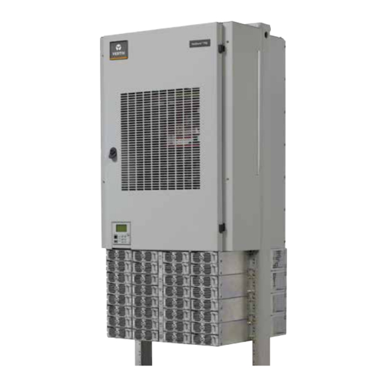
Summary of Contents for Vertiv NetSure 710 Series
- Page 1 NetSure™ 710 Series +24 VDC Power System Quick Start Guide Specification Number: 581127000 Model Number: 710 NPBA...
- Page 2 The information contained in this document is subject to change without notice and may not be suitable for all applications. While every precaution has been taken to ensure the accuracy and completeness of this document, Vertiv assumes no responsibility and disclaims all liability for damages resulting from use of this information or for any errors or omissions.
-
Page 3: Table Of Contents
Vertiv™ NetSure™ 710 Series +24 VDC Power System Quick Start Guide TABLE OF CONTENTS Admonishments Used in this Document ..........................iv Important Safety Instructions ..............................v Safety Admonishments Definitions ............................................v Safety and Regulatory Statements ............................................v Déclarations de Sécurité et de Réglementation ......................................v 1 Customer Documentation Package ..........................1... -
Page 4: Admonishments Used In This Document
Vertiv™ NetSure™ 710 Series +24 VDC Power System Quick Start Guide Admonishments Used in this Document DANGER! Warns of a hazard the reader will be exposed to that will likely result in death or serious injury if not avoided. (ANSI, OSHA) WARNING! Warns of a potential hazard the reader may be exposed to that could result in death or serious injury if not avoided. -
Page 5: Important Safety Instructions
Vertiv™ NetSure™ 710 Series +24 VDC Power System Quick Start Guide Important Safety Instructions Safety Admonishments Definitions Definitions of the safety admonishments used in this document are listed under “Admonishments Used in this Document” on page iv. Safety and Regulatory Statements Refer to Section 4154 (provided with your customer documentation) for Safety and Regulatory Statements. - Page 6 Vertiv™ NetSure™ 710 Series +24 VDC Power System Quick Start Guide This page intentionally left blank. Proprietary and Confidential © 2023 Vertiv Group Corp.
-
Page 7: Customer Documentation Package
Vertiv™ NetSure™ 710 Series +24 VDC Power System Quick Start Guide 1 Customer Documentation Package This document (QS581127000) provides Quick Start Instructions for Vertiv™ NetSure™ +24 VDC Power System Model 710 , Spec. NPBA No. 581127000. The complete Customer Documentation Package consists of…... -
Page 8: Installing Circuit Breakers And Fuses
Vertiv™ NetSure™ 710 Series +24 VDC Power System Quick Start Guide 3 Installing Circuit Breakers and Fuses Load and battery distribution devices were factory-installed if ordered with the power system. If additional installation is required, refer to Figure 3.1 through Figure 3.7. For detailed procedures, refer to Installing Circuit Breakers and Fuses in the INSTALLING THE SYSTEM section of the Installation Instructions (IM581127000). - Page 9 Vertiv™ NetSure™ 710 Series +24 VDC Power System Quick Start Guide Figure 3.2 Installing a Bullet Nose Type Circuit Breaker Shorter Side to the To p Lettering on handle must be Insert these terminals right side up. into corresponding sockets on distribution panel.
- Page 10 Vertiv™ NetSure™ 710 Series +24 VDC Power System Quick Start Guide Figure 3.4 Installing TPL-B Fuses GMT-18/100A Alarm Fuse (P/N 248610301) and GMT-X Safety Fuse Cover (P/N 248898700) (Both are provided w/ fuseblock) Fuse Installed in Open Fuse Case Fuseblock...
- Page 11 Vertiv™ NetSure™ 710 Series +24 VDC Power System Quick Start Guide Figure 3.5 Installing an Optional Bullet Nose Type 6-Position GMT Distribution Fuse Block (P/N 550224) Press in tabs to release lug terminal busbars for positions to be occupied by GMT Fuse Block.
- Page 12 Vertiv™ NetSure™ 710 Series +24 VDC Power System Quick Start Guide Figure 3.6 Installing an Optional Bullet Nose Type 6-Position GMT Distribution Fuse Block (P/N 549017) 1. Remove two lug terminal busbars for positions to be occupied by GMT Fuse Block. Remove plastic busbar plugs first.
- Page 13 Vertiv™ NetSure™ 710 Series +24 VDC Power System Quick Start Guide Figure 3.7 Installing a GJ/218 Circuit Breaker (1-Pole) (Lists AC, AD, BC, BD) (cont’d on next page) INSTALLING CIRCUIT BREAKER Alarm jumper connector. Holes to route shunt jumper through (if applicable).
- Page 14 Vertiv™ NetSure™ 710 Series +24 VDC Power System Quick Start Guide Figure 3.7 Installing a GJ/218 Circuit Breaker (2-Pole, 3-Pole, 4-Pole) (Lists AC, AD, BC, BD) (cont’d from previous page, cont’d on next page) Alarm jumper connectors. INSTALLING CIRCUIT BREAKER Holes to route shunt jumper through (if applicable).
- Page 15 Vertiv™ NetSure™ 710 Series +24 VDC Power System Quick Start Guide Figure 3.7 Installing a GJ/218 Circuit Breaker (1-Pole, 2-Pole, 3-Pole, 4-Pole) (List AM and List AP) (cont’d from previous page) INSTALLING CIRCUIT BREAKER Return Busbar (not included with List AP) Alarm jumper connector.
-
Page 16: Making Jumpers And Switch Options
Vertiv™ NetSure™ 710 Series +24 VDC Power System Quick Start Guide 4 Making Jumpers and Switch Options Various circuit cards installed in the system have switch and jumper settings. Switch Settings: All switch settings set the various circuit cards to operate properly with this system and have been factory set. -
Page 17: Electrical Connections
Vertiv™ NetSure™ 710 Series +24 VDC Power System Quick Start Guide 5 Electrical Connections 5.1 Important Safety Instructions DANGER! Adhere to the “Important Safety Instructions” presented at the front of this document. 5.2 Make Frame Grounding Connections Installation Instructions To do this…... - Page 18 Vertiv™ NetSure™ 710 Series +24 VDC Power System Quick Start Guide Figure 5.1 AC Input and Equipment Grounding Connections to Factory Installed Module Mounting Shelves (cont’d on next page) AC INPUT CONNECTIONS, INDIVIDUAL PCU FEED (581127000 LIST 40), WHEN EQUIPPED WITH 588705201...
- Page 19 Vertiv™ NetSure™ 710 Series +24 VDC Power System Quick Start Guide Figure 5.1 AC Input and Equipment Grounding Connections to Factory Installed Module Mounting Shelves (cont’d from previous page, cont’d on next page) AC INPUT CONNECTIONS, INDIVIDUAL PCU FEED (581127000 LIST 40),...
- Page 20 Vertiv™ NetSure™ 710 Series +24 VDC Power System Quick Start Guide Figure 5.1 AC Input and Equipment Grounding Connections to Factory Installed Module Mounting Shelves (cont’d from previous page, cont’d on next page) AC INPUT CONNECTIONS, INDIVIDUAL PCU FEED (581127000 LIST 40),...
- Page 21 Vertiv™ NetSure™ 710 Series +24 VDC Power System Quick Start Guide Figure 5.1 AC Input and Equipment Grounding Connections to Factory Installed Module Mounting Shelves (cont’d from previous page, cont’d on next page) AC INPUT CONNECTIONS, INDIVIDUAL PCU FEED (581127000 LIST 40),...
- Page 22 Vertiv™ NetSure™ 710 Series +24 VDC Power System Quick Start Guide Figure 5.1 AC Input and Equipment Grounding Connections to Factory Installed Module Mounting Shelves (cont’d from previous page, cont’d on next page) AC INPUT CONNECTIONS, DUAL PCU FEED (581127000 LIST 41),...
- Page 23 Vertiv™ NetSure™ 710 Series +24 VDC Power System Quick Start Guide Figure 5.1 AC Input and Equipment Grounding Connections to Factory Installed Module Mounting Shelves (cont’d from previous page, cont’d on next page) AC INPUT CONNECTIONS, DUAL PCU FEED (581127000 LIST 41),...
- Page 24 Vertiv™ NetSure™ 710 Series +24 VDC Power System Quick Start Guide Figure 5.1 AC Input and Equipment Grounding Connections to Factory Installed Module Mounting Shelves (cont’d from previous page, cont’d on next page) AC INPUT CONNECTIONS, DUAL PCU FEED (581127000 LIST 41),...
- Page 25 Vertiv™ NetSure™ 710 Series +24 VDC Power System Quick Start Guide Figure 5.1 AC Input and Equipment Grounding Connections to Factory Installed Module Mounting Shelves (cont’d from previous page) AC INPUT CONNECTIONS, DUAL PCU FEED (581127000 LIST 41), WHEN EQUIPPED WITH 588705204...
-
Page 26: Make External Interface Connections
Vertiv™ NetSure™ 710 Series +24 VDC Power System Quick Start Guide 5.4 Make External Interface Connections Refer to External Alarm, Reference, Monitoring, and Control Connections in the MAKING ELECTRICAL CONNECTIONS section of the Installation Instructions (IM581127000) for complete procedures. 5.4.1 Circuit Card Locations Refer to Figure 5.2. -
Page 27: System Interface Circuit Card
Vertiv™ NetSure™ 710 Series +24 VDC Power System Quick Start Guide 5.4.2 System Interface Circuit Card The System Interface Circuit Card provides connections for the following. Refer to Figure 5.3. • Battery Tray FA Signal: This input is used to provide a battery tray fuse alarm (FA) on the controller due to a tripped battery disconnect breaker on a battery tray in the power system rack. - Page 28 Vertiv™ NetSure™ 710 Series +24 VDC Power System Quick Start Guide Figure 5.3 System Interface Circuit Card Connections J1, J2, J3, J4 Distribution Panels FA Inputs Selects to power Controller from “Battery Power” or not. Battery Battery Shorting Jumper RS485 Connection...
-
Page 29: Ib2 (Controller Interface Board) Connections (If Required)
Vertiv™ NetSure™ 710 Series +24 VDC Power System Quick Start Guide 5.4.3 IB2 (Controller Interface Board) Connections (if required) The IB2 (Controller Interface Board) provides connection points for digital inputs, programmable relay outputs, and temperature probes. The IB2 interface board is mounted inside the distribution cabinet. Refer to Figure 5.2. - Page 30 Vertiv™ NetSure™ 710 Series +24 VDC Power System Quick Start Guide The relays may be preprogrammed for specific functions. Refer to the configuration drawing (C-drawing) supplied with your system for your system’s specific configuration. Temperature Probes NOTE! Each temperature probe consists of two or three pieces that plug together to make a complete probe. See SAG581127000 for part numbers and descriptions.
- Page 31 Vertiv™ NetSure™ 710 Series +24 VDC Power System Quick Start Guide Figure 5.4 IB2 (Interface Board) Connections Schematic Diagram of IB2 Board IB2 TEMP IB2 TEMP PROBE 2 PROBE 1 DI1- DI1+ DI2- DI2+ DI3- DI3+ DI4- DI4+ DI5- DI5+...
- Page 32 Vertiv™ NetSure™ 710 Series +24 VDC Power System Quick Start Guide Table 5.1 Programmable Digital Inputs – IB2 Board Programmable Factory Default Digital Customer Defined Digital Input Pin No. Wiring Input Function Digital Input Function J3-2 J3-1 – J3-4 J3-3 –...
- Page 33 Vertiv™ NetSure™ 710 Series +24 VDC Power System Quick Start Guide Table 5.2 Programmable Relay Outputs – IB2 Board Programmable Relay Alarms Assigned to this Relay (Default) Alarms Assigned to this Relay (Custom) Output Pin No. J6-5 J6-3 J6-1 J6-6...
-
Page 34: Optional Eib (Controller Extended Interface Board) Connections (If Required)
Vertiv™ NetSure™ 710 Series +24 VDC Power System Quick Start Guide 5.4.4 Optional EIB (Controller Extended Interface Board) Connections (if required) The optional EIB (Controller Extended Interface Board) provides additional connection points for voltage and current inputs, programmable relay outputs, and temperature probes. The EIB extended interface board is mounted inside the distribution cabinet. - Page 35 Vertiv™ NetSure™ 710 Series +24 VDC Power System Quick Start Guide Figure 5.5 Sample Battery Block or Battery Midpoint Monitoring Connections Battery Block Monitoring +24V Load Shunt Load Rectifiers Battery Battery Battery Battery Return String 1 String 2 String 3...
- Page 36 Vertiv™ NetSure™ 710 Series +24 VDC Power System Quick Start Guide Programmable Relay Outputs The EIB provides five (5) programmable alarm relays with dry Form-C contacts. Connect up to five (5) relay outputs to the EIB. Refer to Figure 5.6 for terminal locations and Table 5.4 for pin-out information.
- Page 37 Vertiv™ NetSure™ 710 Series +24 VDC Power System Quick Start Guide Figure 5.6 EIB (Extended Interface Board) Connections Schematic Diagram of EIB Board EIB Board D12_NO D11_NO D12_COM D11_COM D12_NC D11_NC D10_NO DO9_NO D10_COM DO9_COM D10_NC DO9_NC D13_NO D13_COM DCV8...
- Page 38 Vertiv™ NetSure™ 710 Series +24 VDC Power System Quick Start Guide Table 5.3 Shunt Inputs – EIB Factory Default Customer Shunt Input Pin No. Wiring Function Defined Function J5-2 none J5-1 – J5-4 none J5-3 – J5-6 none J5-5 –...
-
Page 39: Optional Sm-Du+ And Shunt Interface Board
Vertiv™ NetSure™ 710 Series +24 VDC Power System Quick Start Guide Table 5.5 Programmable Relay Outputs – EIB Programmable Relay Alarms Assigned to this Relay (Default) Alarms Assigned to this Relay (Custom) Output Pin No. J8-5 J8-3 J8-1 J8-6 J8-4... - Page 40 Vertiv™ NetSure™ 710 Series +24 VDC Power System Quick Start Guide Figure 5.7 SM-DU+ and Shunt Interface Board Connections Schematic Diagram of SM-DU+ and Shunt Interface Board Shunt Interface Board SMDU+ SHUNT INTERFACE SHUNT25+ SHUNT25- SHUNT24+ SHUNT24- SHUNT23+ SHUNT23- SHUNT22+...
-
Page 41: Connecting A Device Or System To The Controller's Can Bus
Vertiv™ NetSure™ 710 Series +24 VDC Power System Quick Start Guide 5.4.6 Connecting a Device or System to the Controller’s CAN Bus • A supporting device or system may be connected to the Controller’s CAN Port. Refer to Figure 5.3 for location. Refer to Table 5.6 for pin-outs. -
Page 42: Make Controller Ethernet Connection (If Required)
Vertiv™ NetSure™ 710 Series +24 VDC Power System Quick Start Guide 5.5 Make Controller Ethernet Connection (if required) If the Web Interface will be used, connect to the Ethernet port on the front of the Controller. Location is shown in Figure 5.8. - Page 43 Vertiv™ NetSure™ 710 Series +24 VDC Power System Quick Start Guide Ethernet Connection through the Power System The Ethernet cable can be routed from the notch on the left side of the bracket. It goes through the lances on the chassis, then goes up to be bundled with the harness and all other customer alarm and signal cables.
- Page 44 Vertiv™ NetSure™ 710 Series +24 VDC Power System Quick Start Guide NCU Controller Second Ethernet Port Connection (if IB4 board furnished) Your system may be furnished with an IB4 board connected to the NCU backplane via a factory furnished and connected cable. The IB4 board provides a second Ethernet port.
-
Page 45: Make Load Connections
Vertiv™ NetSure™ 710 Series +24 VDC Power System Quick Start Guide 5.6 Make Load Connections Refer to Load Connections in the MAKING ELECTRICAL CONNECTIONS section of the Installation Instructions (IM581127000) for complete procedures. Loads are connected to the various distribution panels located inside the distribution cabinet. See Figure 5.11 through Figure 5.33. -
Page 46: Load Connections To Single Voltage Distribution Panels
Vertiv™ NetSure™ 710 Series +24 VDC Power System Quick Start Guide 5.6.2 Load Connections to Single Voltage Distribution Panels Figure 5.11 List AA: +24V Distribution Panel (with Return Busbar) and List AB: +24V Distribution Panel (without Return Busbar), (24) Bullet/TPS/TLS Circuit Breaker/Fuse Positions... - Page 47 Vertiv™ NetSure™ 710 Series +24 VDC Power System Quick Start Guide Figure 5.13 List AE: +24V Distribution Panel, (2) TPH Fuse Positions (without Shunts) (without Return Busbar) +24VDC Load Connections LOAD CONNECTIONS 3/8-16 Captive Nuts on 1” Centers (Customer must supply or order additional hardware) Maximum Lug Width: 1.88 inches.
- Page 48 Vertiv™ NetSure™ 710 Series +24 VDC Power System Quick Start Guide Figure 5.15 List AG: +24V Distribution Panel, (4) TPH Fuse Positions (without Shunts) (without Return Busbar) +24VDC Load LOAD CONNECTIONS Connections 3/8-16 Captive Nuts on 1” Centers (Customer must supply or order additional hardware) Maximum Lug Width: 1.75 inches.
- Page 49 Vertiv™ NetSure™ 710 Series +24 VDC Power System Quick Start Guide Figure 5.17 List AJ: +24V Distribution Panel, (4) TPL-B Fuse Positions (without Shunts) (without Return Busbar) +24VDC Load Connections LOAD CONNECTIONS 3/8-16 Studs on 1” Centers (Customer must supply or order additional hardware) Maximum Lug Width: 1.5 inches.
- Page 50 Vertiv™ NetSure™ 710 Series +24 VDC Power System Quick Start Guide Figure 5.19 List AL and List AN: +24V Distribution Panel, (26) Bullet/TPS/TLS Circuit Breaker/Fuse Positions Return Busbar LOAD AND LOAD RETURN CONNECTIONS (not included with List AN) 1/4-20 Studs on 5/8” Centers...
-
Page 51: Load Connections To Dual Voltage Distribution Panels
Vertiv™ NetSure™ 710 Series +24 VDC Power System Quick Start Guide 5.6.3 Load Connections to Dual Voltage Distribution Panels Figure 5.21 List DA: +24V/-48V Distribution Panel, (17) +24V Bullet/TPS/TLS Circuit Breaker/Fuse Positions (with Return Busbar) and (4) -48V Bullet/TPS/TLS Circuit Breaker/Fuse Positions (with Return Busbar) LOAD AND LOAD RETURN CONNECTIONS 1/4-20 Studs on 5/8”... - Page 52 Vertiv™ NetSure™ 710 Series +24 VDC Power System Quick Start Guide Figure 5.23 List DC: +24V/-48V Distribution Panel, (9) +24V Bullet/TPS/TLS Circuit Breaker/Fuse Positions (with Return Busbar) and (12) -48V Bullet/TPS/TLS Circuit Breaker/Fuse Positions (with Return Busbar) LOAD AND LOAD RETURN CONNECTIONS 1/4-20 Studs on 5/8”...
- Page 53 Vertiv™ NetSure™ 710 Series +24 VDC Power System Quick Start Guide Figure 5.25 List DE: +24V/-48V Distribution Panel, (22) +24V Bullet/TPS/TLS Circuit Breaker/Fuse Positions (with Return Busbar) and (4) -48V Bullet/TPS/TLS Circuit Breaker/Fuse Positions (with Return Busbar) LOAD AND LOAD RETURN CONNECTIONS 1/4-20 Studs on 5/8”...
- Page 54 Vertiv™ NetSure™ 710 Series +24 VDC Power System Quick Start Guide Figure 5.27 List DG: +24V/-48V Distribution Panel, (14) +24V Bullet/TPS/TLS Circuit Breaker/Fuse Positions (with Return Busbar) and (12) -48V Bullet/TPS/TLS Circuit Breaker/Fuse Positions (with Return Busbar) LOAD AND LOAD RETURN CONNECTIONS 1/4-20 Studs on 5/8”...
- Page 55 Vertiv™ NetSure™ 710 Series +24 VDC Power System Quick Start Guide Figure 5.29 List DJ: +24V/-48V Distribution Panel, (6) +24V Bullet/TPS/TLS Circuit Breaker/Fuse Positions (with Return Busbar) and (20) -48V Bullet/TPS/TLS Circuit Breaker/Fuse Positions (with Return Busbar) LOAD AND LOAD RETURN CONNECTIONS 1/4-20 Studs on 5/8”...
-
Page 56: Load Connections To Return Bar
Vertiv™ NetSure™ 710 Series +24 VDC Power System Quick Start Guide 5.6.4 Load Connections to Return Bar Figure 5.31 List GA: Return Bar Panel Load and/or Battery Return Connections LOAD AND/OR BATTERY RETURN CONNECTIONS 3/8-16 Captive Nuts on 1” Centers (Customer must supply or order additional hardware) Maximum Lug Width: 1.38 inches. -
Page 57: Load Connections To Gmt Distribution Fuse Block
Vertiv™ NetSure™ 710 Series +24 VDC Power System Quick Start Guide 5.6.6 Load Connections to GMT Distribution Fuse Block Figure 5.33 Optional Bullet Nose 6-Position GMT Distribution Fuse Block Load Return Leads +24VDC Load Leads P/N 550224 1/4-20 Hardware. Torque to 75 in-lbs. -
Page 58: Make Battery Connections
Vertiv™ NetSure™ 710 Series +24 VDC Power System Quick Start Guide 5.7 Make Battery Connections Refer to Battery Connections in the MAKING ELECTRICAL CONNECTIONS section of the Installation Instructions (IM581127000) for complete procedures. 5.7.1 Recommended Torques • 72 in-lbs for 1/4-inch hardware (when using standard flat and lock washer). - Page 59 Vertiv™ NetSure™ 710 Series +24 VDC Power System Quick Start Guide Figure 5.35 List BC: Battery Disconnect Distribution Panel (with Return Busbar) and List BD: Battery Disconnect Distribution Panel (without Return Busbar), (4) GJ/218 Circuit Breaker Battery Disconnect Positions BATTERY AND BATTERY RETURN CONNECTIONS 3/8-16 Captive Nuts on 1”...
- Page 60 Vertiv™ NetSure™ 710 Series +24 VDC Power System Quick Start Guide Figure 5.37 List BF: Battery Disconnect Distribution Panel, (2) TPH Fuse Battery Disconnect Positions (with Shunts) (without Return Busbar) BATTERY CONNECTIONS 3/8-16 Captive Nuts on 1” Centers Maximum Lug Width: 1.88 inches.
- Page 61 Vertiv™ NetSure™ 710 Series +24 VDC Power System Quick Start Guide Figure 5.39 List BH: Battery Disconnect Distribution Panel, (4) TPH Fuse Battery Disconnect Positions (with Shunts) (without Return Busbar) Maximum Lug Width: 1.75 inches. BATTERY CONNECTIONS Maximum fuse size is 400A.
-
Page 62: Battery Connections To Distribution Cabinet Battery Busbars
Vertiv™ NetSure™ 710 Series +24 VDC Power System Quick Start Guide 5.7.3 Battery Connections to Distribution Cabinet Battery Busbars WARNING! Observe proper polarity when making battery connections. Battery may be connected to the battery busbars located in the distribution cabinet, as detailed in Figure 5.40, depending on site requirements. -
Page 63: List 93 Battery Tray
Vertiv™ NetSure™ 710 Series +24 VDC Power System Quick Start Guide 5.8 List 93 Battery Tray Refer to Installing and Connecting Batteries in a List 93 Battery Tray (if furnished) in the MAKING ELECTRICAL CONNECTIONS section of the Installation Instructions (IM581127000) for a complete procedure. - Page 64 Vertiv™ NetSure™ 710 Series +24 VDC Power System Quick Start Guide Figure 6.1 Module Location Diagrams (on the front of each shelf) Figure 6.2: Handle/Latch Operation on the Rectifier and DC-DC Converter Modules Proprietary and Confidential © 2023 Vertiv Group Corp.
-
Page 65: Initially Starting, Configuring, And Checking System Operation
Vertiv™ NetSure™ 710 Series +24 VDC Power System Quick Start Guide 7 Initially Starting, Configuring, and Checking System Operation CAUTION! Performing various steps in the following procedures may cause a service interruption and/or result in the extension of alarms. Notify any appropriate personnel before starting these procedures. Also, notify personnel when these procedures are completed. - Page 66 Vertiv™ NetSure™ 710 Series +24 VDC Power System Quick Start Guide Figure 7.1 ACU+ Local Indicators and Navigation Keys Minor Alarm Indicator ( Yellow) Status Critical or Major Indicator Alarm Indicator (Green) (Red) Ethernet Port Port Menu Navigation Keys Procedure NOTE! The initialization routine takes several minutes.
- Page 67 Vertiv™ NetSure™ 710 Series +24 VDC Power System Quick Start Guide From the Main screen, press ENT to go to the “Main Menu” screen. From the Main Menu, select a submenu by repetitively pressing the up or down arrow key. The selected submenu will be indicated by the cursor.
- Page 68 Vertiv™ NetSure™ 710 Series +24 VDC Power System Quick Start Guide Checking Basic System Settings Navigate through the controller menus and submenus to check system settings. You can adjust any parameter as required. Note that these settings can also be checked (and changed if required) via the WEB Interface.
- Page 69 Vertiv™ NetSure™ 710 Series +24 VDC Power System Quick Start Guide Table 7.1 ACU+ Basic Settings Menu Navigation Parameter Menu Navigation Date Main Menu / Settings / Controller / Date Time Main Menu / Settings / Controller / Time IP Communications Parameters...
- Page 70 Vertiv™ NetSure™ 710 Series +24 VDC Power System Quick Start Guide Configuring the ACU+ Identification of Rectifiers and Assigning which Input Phase is Connected to the Rectifiers When rectifiers are all installed prior to applying power and starting the system, the order in which the ACU+ identifies the rectifiers is by serial number (lowest serial number is Rect 1, next lowest is Rect 2, etc.).
- Page 71 Vertiv™ NetSure™ 710 Series +24 VDC Power System Quick Start Guide If you prefer the ACU+ to identify the converters by position in the system, perform the following procedure. Procedure With the Main screen displayed, press ENT to go to the Main Menu. Navigate to and select “Settings” (ENT).
-
Page 72: Ncu Controller Procedure
Vertiv™ NetSure™ 710 Series +24 VDC Power System Quick Start Guide 7.4 NCU Controller Procedure Refer to this section if your system is furnished with an NCU Controller. NCU Controller Initialization Refer to the NCU Instructions (UM1M830BNA) for detailed instructions. - Page 73 Vertiv™ NetSure™ 710 Series +24 VDC Power System Quick Start Guide Figure 7.3 NCU Local Display Main Menu Main Menu The number in ( ) indicates Date and time are Green - No Alarm the total number of alarms. alternately displayed.
- Page 74 Vertiv™ NetSure™ 710 Series +24 VDC Power System Quick Start Guide NCU Start Wizard For initial startup, you can perform the Start Wizard from the local keypad and display to enter basic programmable parameters in one session. Refer to the “Start Wizard” section in the NCU Instructions (UM1M830BNA).
- Page 75 Vertiv™ NetSure™ 710 Series +24 VDC Power System Quick Start Guide Table 7.2 NCU Basic Settings Menu Navigation Parameter Menu Navigation Date Main Menu / Settings Icon / Sys Settings / Date. Time Main Menu / Settings Icon / Sys Settings / Time.
- Page 76 Vertiv™ NetSure™ 710 Series +24 VDC Power System Quick Start Guide Configuring the NCU Identification of Converters When converters are all installed prior to applying power and starting the system, the order in which the NCU identifies the converters is by serial number (lowest serial number is Conv 1, next lowest is Conv 2, etc.). If you prefer the NCU to identify the converters by position in the system, perform the following procedure.
-
Page 77: Checking System Status
Vertiv™ NetSure™ 710 Series +24 VDC Power System Quick Start Guide 7.5 Checking System Status Procedure Observe the status of the indicators located on the controller, rectifiers, and converters (if furnished). If the system is operating normally, the status of these is as shown in Table 7.3. - Page 78 Vertiv™ NetSure™ 710 Series +24 VDC Power System Quick Start Guide This page intentionally left blank. Proprietary and Confidential © 2023 Vertiv Group Corp.
- Page 79 Vertiv™ NetSure™ 710 Series +24 VDC Power System Quick Start Guide Connect with Vertiv on Social Media https://www.facebook.com/vertivI https://www.instagram.com/vertiv/ https://www.linkedin.com/company/vertiv/ https://www.twitter.com/vertiv/ Proprietary and Confidential © 2023 Vertiv Group Corp.
- Page 80 Vertiv.com | Vertiv Headquarters, 505 N Cleveland Ave, Westerville, OH 43082, USA © 2023 Vertiv Group Corp. All rights reserved. Vertiv™ and the Vertiv logo are trademarks or registered trademarks of Vertiv Group Corp. All other names and logos referred to are trade names, trademarks or registered trademarks of their respective owners. While every precaution has been taken to ensure accuracy and completeness here, Vertiv Group Corp.
Need help?
Do you have a question about the NetSure 710 Series and is the answer not in the manual?
Questions and answers