Table of Contents
Advertisement
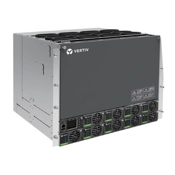
NetSure 731 A91 插框电源系统
用户手册
资料版本 V1.0
归档日期 2019-08-27
BOM 编码 31013961
维谛技术有限公司为客户提供全方位的技术支
持,用户可与就近的维谛技术有限公司办事处
或客户服务中心联系,也可直接与公司总部联
系。
维谛技术有限公司
版权所有,保留一切权利。内容如有改动,恕
不另行通知。
维谛技术有限公司
地址: 深圳市南山区学苑大道 1001 号南山智园
B2 栋
邮编:518055
公司网址:www.vertiv.com
客户服务热线:4008876510
E-mail:vertivc.service@vertiv.com
NetSure 731 A91 Subrack Power
System
User Manual
Version
V1.0
Revision date August 27, 2019
BOM
31013961
Vertiv Tech provides customers with technical
support. Users may contact the nearest Vertiv
local sales office or service center.
Copyright © 2019 by Vertiv Tech Co., Ltd.
All rights reserved. The contents in this document
are subject to change without notice.
Vertiv Tech Co., Ltd.
Address: Block B2, Nanshan I Park, No.1001
Xueyuan Road, Nanshan District, Shenzhen,
518055, P.R.China
Homepage: www.vertiv.com
E-mail: overseas.support@vertiv.com
Advertisement
Table of Contents

Related Manuals for Vertiv NetSure 731 A91


Summary of Contents for Vertiv NetSure 731 A91
- Page 1 Users may contact the nearest Vertiv 持,用户可与就近的维谛技术有限公司办事处 local sales office or service center. 或客户服务中心联系,也可直接与公司总部联 系。 Copyright © 2019 by Vertiv Tech Co., Ltd. 维谛技术有限公司 All rights reserved. The contents in this document 版权所有,保留一切权利。内容如有改动,恕 are subject to change without notice.
- Page 3 When operating Vertiv products, the safety rules in the industry, the general safety points and special safety instructions specified in this book must be strictly observed.
- Page 4 IV. ESD Notice The static electricity generated by the human body will damage the static sensitive elements on PCBs, such as large-scale ICs. Before touching any plug-in board, PCB or IC chip, ESD wrist strap must be worn to prevent body static from damaging the sensitive components.
- Page 5 Battery installation requires reliable grounding. And battery is connected before accessing the battery protection device. Others I. Sharp object Warning When moving equipment by hand, protective gloves should be worn to avoid injury by sharp object. II. Cable connection Notice Please verify the compliance of the cable and cable label with the actual installation prior to cable connection.
-
Page 7: Table Of Contents
Contents Chapter 1 Overview ................................1 1.1 Composition and Configuration ..........................1 Chapter 2 Installation Instruction ............................3 2.1 Safety Regulation ..............................3 2.2 Preparation ................................3 2.3 Mechanical Installation ............................4 2.4 Electrical Installation ............................. 5 2.4.1 Power System Cabling Method ......................... 5 2.4.2 Connecting AC Input Cables ........................ -
Page 9: Chapter 1 Overview
Chapter 1 Overview Chapter 1 Overview This chapter introduces model composition and configuration and features of NetSure 731 A91-S1, NetSure 731 A91-S2 and NerSure 731 A91-S3 (abbreviated as 'power system' hereinafter). 1.1 Composition and Configuration Composition The power system is composed of power distribution、rectifier modules and controller module. - Page 10 Ethernet and CAN), which enables flexible networking and remote monitoring. ⚫ The power system has perfect lighting protection at both AC side and DC side. ⚫ The power system has complete fault protection and fault alarm functions. NetSure 731 A91 Subrack Power System User Manual...
-
Page 11: Chapter 2 Installation Instruction
The equipment should be unpacked and inspected after it arrives at the installation site. The inspection shall be done by representatives of both the user and Vertiv Tech Co., Ltd. To inspect the equipment, you should open the packing case, take out the packing list and check against the packing list that the equipment is correct and complete. -
Page 12: Mechanical Installation
Fix the subrack power system to the battery rack through the connectors with M6 bolts, as show in Figure 2-1. Power system M6 screw M6 screw Connector Connector Battery rack Figure 2-1 Cabinet and rack installation NetSure 731 A91 Subrack Power System User Manual... -
Page 13: Electrical Installation
3. Please plug in the new modules or installing a new panel after removing the rectifier module. 2.4 Electrical Installation 2.4.1 Power System Cabling Method Cabling from the top of the power system The top cover is rubber ring top cover. NetSure 731 A91 Subrack Power System User Manual... - Page 14 When the subrack is installed independently on the outside (not installed in the rack). Using system side outlet. The clearance of the outlet hole must be sealed after connecting the cable to prevent it from touching the live part of the frame. Screw Screw Cable hole Cable hole Figure 2-5 Side cabling NetSure 731 A91 Subrack Power System User Manual...
-
Page 15: Connecting Ac Input Cables
2. Only the qualified personnel can do the mains cable connection. For NetSure 731 A91-S1 power system, the position of the connection terminals are shown in Figure 2-6.After connecting AC cables, fixing cables on top or side cable banding area by using cable ties. -
Page 16: Connecting Battery Cables
The standard configuration of the system is M830B controller. The MA4C5U31 user interface board is used for M830B. M830B controller and MA4C5U31 user interface board cable connection is show in the following: NetSure 731 A91 Subrack Power System User Manual... - Page 17 Ethernet port USB口 Figure 2-10 M830B controller communication port Connecting NetSure 731 A91-S2 Signal Cables The standard configuration of the system is M530B controller. Netsure 731 A91-S2 user interface board position as shown in Figure 2-11. Signal cable User interface terminal (DI/ DO board)...
- Page 18 Chapter 2 Installation Instruction Connecting Communication Signal Cable The communication port of M530B controller is shown in Figure 2-12. 以太网口 Ethernet port USB口 Figure 2-12 M530B controller communication port NetSure 731 A91 Subrack Power System User Manual...
-
Page 19: Chapter 3 Commissioning
Check the system voltage and busbar polarity with a voltmeter. The voltage difference between the measured value and displayed value should be less than±0.2V. Start and stop each rectifier of the system by inserting and unplugging the rectifier. Check their output voltages. NetSure 731 A91 Subrack Power System User Manual... -
Page 20: Basic Settings
Remove all the battery MCBs. Keep only one rectifier in operation. Through the controller module, adjust the rectifier FC voltage to make it lower than the alarm point. The alarm ‘DC Voltage Low’ should be triggered NetSure 731 A91 Subrack Power System User Manual... -
Page 21: Final Steps
If any defect is found in this equipment, inform the personnel responsible for the contract. If repairing is needed, please fill in the FAILURE REPORT and send the report together with the defective unit to the repairing center for fault analysis. NetSure 731 A91 Subrack Power System User Manual... -
Page 22: Chapter 4 Troubleshooting
2. Switch off the AC input of all rectifiers. 3. Power on the rectifiers one by one. 4. If the over-voltage protection is triggered when a certain rectifier is powered on, that rectifier is the faulty one. Replace it NetSure 731 A91 Subrack Power System User Manual... - Page 23 Check if the corresponding MCB is switched off. If the MCB is open, find out the fault and remove it. Alarm, Batt Otherwise, the alarm circuit is faulty. Please contact Vertiv. Fuse Alarm 1. Check if there is mains failure, and the battery voltage is lower than the value of ‘LVD2’.
-
Page 24: Rectifier Fault Handling
Power factor compensation internal Rect protection Replace the rectifier under voltage or over voltage Protection indicator Check whether the communication Rect communication fail Rectifier communication fail flash (yellow) cable is in normal connection NetSure 731 A91 Subrack Power System User Manual... - Page 25 Verify that the rectifiers are operating normally. 10. Enable the external alarms, or notify appropriate personnel that this procedure is finished. 11. Ensure that there are no local or remote alarms active on the system. NetSure 731 A91 Subrack Power System User Manual...
-
Page 26: Rectifier Fan Replacement
7. Install the front panel with the new fan onto the chassis by plugging the fan cable into the printed circuit card, and securing the front panel with the screws previously removed. NetSure 731 A91 Subrack Power System User Manual... - Page 27 8. Replace the Rectifier into the shelf. Refer to the previous procedure for step-by-step instructions. 9. Enable the external alarms, or notify appropriate personnel that this procedure is finished. 10.Ensure that there are no local or remote alarms active on the system. Figure 4-5 Fan replacement NetSure 731 A91 Subrack Power System User Manual...
-
Page 28: Appendix 1 Technical And Engineering Data
AC input under-voltage Default: 80 ± 5Vac, configurable through controller protection point AC input under-voltage Default: 95 ± 5Vac, 10Vac higher than the AC input under-voltage alarm point protection recovery point NetSure 731 A91 Subrack Power System User Manual... - Page 29 M830B controller) Harmonic current emission EN61000-3-12 Voltage fluctuation and flash EN61000-3-11 Level 4 EN/IEC 61000-4-4 Level 3 EN/IEC 61000-4-2 Surges Level 4 EN/IEC 61000-4-5 Radiation Level 3 EN/IEC 61000-4-3 Conduction Level 3 EN/IEC61000-4-6 NetSure 731 A91 Subrack Power System User Manual...
- Page 30 Standard dimensions of the 352mm×483mm×400 subracks: M830B: 43.4mm×210.3mm×85.9mm Dimensions (mm) Controller: M530B: 43mm×86mm×210mm R48-3000e3: 41mm×84.5mm×330mm Rectifier: Mechanical R48-3500e3:41mm×84.5mm×330mm Subrack (package,rectifier and ≤60; controller are all included) Weight (kg) Subrack (without ≤40; package,rectifier and controller included) NetSure 731 A91 Subrack Power System User Manual...
-
Page 31: Appendix 2 Installation Instruction Of Battery Rack
1) Install accessory 1 and accessory 2 according to Figure 2 (a). 2) Install accessory 3 according to Figure 2 (b). Accessory 1 Accessory 3 Accessory 2 Figure 2 Installation procedure of accessory 1 ~ accessory 3 NetSure 731 A91 插框电源系统 用户手册... - Page 32 2) Install accessory 5 according to Figure 4 (a). 3) Install accessory 2 and accessory 4 according to Figure 4 (b). Accessory 4 Accessory 2 Figure 4 Installation procedure of accessory 2, accessory 4 and accessory 5 NetSure 731 A91 Subrack Power System User Manual...
-
Page 33: Installation Instruction Of Three-Layer Battery Rack
1. Install accessory 1 and accessory 2 according to Figure 6 (a). 2. Install accessory 3 according to Figure 6 (b). Accessory 2 Accessory 1 Accessory 3 Figure 6 Installation procedure of accessory 1 ~ accessory 3 NetSure 731 A91 插框电源系统 用户手册... -
Page 34: Fixing The Battery Rack
1. Fix the battery rack to the ground according to the installation dimensions shown in Figure 8. The fixing bolts are accessories. Figure 8 Installation dimensions (unit: mm) 2. Fix the subrack subrack power system onto the top of the battery rack. Refer to2.3 Mechanical Installation NetSure 731 A91 Subrack Power System User Manual... -
Page 35: Appendix 3 Wiring Diagram
Appendix 3 Wiring Diagram Appendix 3 Wiring Diagram NetSure 731 A91 Subrack Power System User Manual... - Page 36 Appendix 3 Wiring Diagram Figure 1 NetSure 731 A91-S1/S3 wiring diagram NetSure 731 A91 Subrack Power System User Manual...
- Page 37 Appendix 3 Wiring Diagram NetSure 731 A91 Subrack Power System User Manual...
- Page 38 Appendix 3 Wiring Diagram Figure 2 NetSure 731 A91-S2 wiring diagram NetSure 731 A91 Subrack Power System User Manual...
-
Page 39: Appendix 4 Schematic Diagram
Battery string 4 DC SPD QFB4 AC input CAN+ CAN- QFA1 CAN+ CAN- Positive busbar L1 L2 L3 N L1 L2 L3 N Figure 3 Schematic diagram of NetSure 731 A91 S1/S3 NetSure 731 A91 Subrack Power System User Manual... - Page 40 Battery string 4 DC SPD QFB4 AC input CAN+ CAN- QFA1 CAN+ CAN- Positive busbar L1 L2 L3 N L1 L2 L3 N Figure 4 Schematic diagram of NetSure 731 A91 S2 NetSure 731 A91 Subrack Power System User Manual...
Need help?
Do you have a question about the NetSure 731 A91 and is the answer not in the manual?
Questions and answers