Ametek dunkermotoren BGE 6060 A Translation Of The Original Function And Connection Manual
Hide thumbs
Also See for dunkermotoren BGE 6060 A:
- Operation manual (32 pages) ,
- Operation manual (65 pages)

Related Manuals for Ametek dunkermotoren BGE 6060 A


Summary of Contents for Ametek dunkermotoren BGE 6060 A
- Page 1 Original Funktions- und Anschlussbeschreibung/ Translation of the original function and connection guide BGE 6060 A Typ: Part No: BGE 6060 A 88740.01260...
-
Page 2: Table Of Contents
Content Inhalt 1. About this Documentation ....6 1. Zu dieser Dokumentation...... 6 Liability and Warranty .......... 7 Haftung und Gewährleistung ....... 7 Target Group ............7 Zielgruppe ............7 Safety Notes ............7 Sicherheitshinweise ..........7 Icons ..............8 Piktogramme ............ - Page 3 5. Technical data, accessories....19 5. Technische Daten, Zubehör ....19 Product specification ......... 19 Produktspezifikation .......... 19 General features ..........20 Allgemeine Eigenschaften ......... 20 Current characteristics ........21 Stromkennlinien ..........21 Dimensions ............22 Maßzeichnung ..........22 6. Installation ..........23 6.
- Page 4 7.1.3 Project Window ..........46 7.1.3 Projektfenster ............ 46 7.1.5 Short description of PI modules ......47 7.1.5 Kurzbeschreibung PI Module ......47 7.1.5.1 PI 100 Positioning module „Standard“ ... 47 7.1.5.1 PI 100 Positioning module „Standard“ ... 47 7.1.5.2 PI 110 Positioning module „Stepper“ ....48 7.1.5.2 PI 110 Positioning module „Stepper“...
- Page 5 8. Maintenance ......... 79 8. Wartung ..........79 9. Decommissioning and Disposal ..80 9. Außerbetriebnahme und Entsorgung 80 10. Service and Support ......80 10. Service und Support ......80 11. Imprint ........... 81 11. Impressum ..........81 Page/Seite 5 / 83 Version 2.0 / 28-02-2024 BGE 6060 A...
-
Page 6: About This Documentation
About this Documentation Zu dieser Dokumentation This documentation is targeted at people who are Diese Dokumentation richtet sich an Personen, die mit charged with transport, assembly and connection of the Transport, Montage und Anschluss des Produkts beauf- product. tragt sind. In the following, the BGE 6060 A is referred to as „pro- Im nachfolgenden wird die BGE 6060 A als „Produkt“... -
Page 7: Liability And Warranty
Liability and Warranty Haftung und Gewährleistung Dunkermotoren GmbH does not accept any liability or Die Dunkermotoren GmbH übernimmt keine Haftungs- warranty claims for personal injury or damage to property und Gewährleistungsansprüche für Personen- und Sach- if they are attributable to one or several of the following schäden, wenn sie auf einen oder mehrere der folgenden causes: Ursachen zurückzuführen sind:... -
Page 8: Icons
Icons Piktogramme This document uses the following icons: In diesem Dokument werden folgende Piktogramme verwendet: Symbol/ Meaning/ Symbol Bedeutung Observe operating instructions/ Gebrauchsanweisung beachten Earth before use/ Vor Benutzung erden Recommendations/ Empfehlungen Instruction to act/ Handlungsaufforderung Hazard Signs Gefahrenzeichen The hazard signs inform about potential hazards and Die Gefahrenzeichen weisen auf mögliche Gefahren hin name measures to avoid risks. -
Page 9: Ec/Eu Declaration Of Conformity
EC/EU Declaration of Conformity EG/EU-Konformitätserklärung With the EC/EU declaration of conformity, the manufac- Mit der EG-/EU-Konformitätserklärung bescheinigt der turer confirms that he has met all basic safety and health Hersteller, alle grundlegenden Sicherheits- und Gesund- requirements of of the applicable directive. heitsanforderungen der anzuwendenden Richtlinie erfüllt zu haben. -
Page 10: Safety Notes
Safety Notes Sicherheitshinweise The safety notes are only part of the technical documen- Die Sicherheitshinweise sind nur ein Teil der technischen tation of this product. They must be read in connection Dokumentation dieses Produkts. Sie sind im Zusammen- with the other technical documentation. hang mit den anderen technischen Dokumentationen zu sehen. -
Page 11: Basic Safety Notes
Basic Safety Notes Grundlegende Sicherheitshinweise Only use the product in an impeccable condition. Verwenden Sie das Produkt nur im einwandfreien Zustand. Observe the technical data and environmental condi- tions indicated in the documentation. Halten Sie die in der Dokumentation angegebenen technischen Daten und Umgebungsbedingungen ein. -
Page 12: Safety Notes Concerning Operating Phases
Safety Notes concerning Operating Phases Sicherheitshinweise zu Betriebsphasen 2.5.1 Transport 2.5.1 Transport Transport the product contoller only in its original Transportieren Sie das Produkt nur in der Originalver- packaging. packung. Ensure that the transported goods are sufficiently Sorgen Sie für ausreichende Sicherung des Transport- secured. -
Page 13: Environmentally Compatible Disposal
2.5.5 Umweltgerecht entsorgen 2.5.5 Environmentally Compatible Disposal Dispose of the product and/or exchange parts safely Entsorgen Sie das Produkt und/oder Austauschteile sicher und umweltschonend. and in an environmentally sound manner. Beachten Sie landesspezifische Vorschriften, Gesetze Observe the country-specific regulations, laws and provisions. -
Page 14: Transport And Storage
Transport and Storage Transport und Lagerung Observe the environmental conditions during transport Beachten Sie bei Transport und Lagerung die Umge- and storage. If your storage and transport conditions bungsbedingungen. Falls Sie davon abweichende Lage- deviate from these (see table below), please contact us so rungs- und Transportbedingungen haben (siehe Tabelle that we can review potential impacts on your products. -
Page 15: Product Description
Product Description Produktbeschreibung Baureihe Series » The electronic controller BGE 6060 A is a 4-quadrant » Bei der Steuerungselektronik BGE 6060 A handelt position controller with integral output stage and es sich um eine 4-Quadranten-Positioniersteuerung an interface for stand-alone operation controlled by mit integrierter Endstufe und Schnittstellen für den digital or analogue inputs or outputs or for operation Stand-alone Betrieb gesteuert über digitale oder... -
Page 16: Types Of Operation
Types of operation Betriebsarten The external controller can be operated in the following Der externe Regler kann in den folgenden Betriebsarten modes: betrieben werden: » Slave in CANopen networks » Slave in CANopen Netzwerken » Stand-alone operation Stand-alone Betrieb » 4.3.1 Slave in CANopen networks 4.3.1 Slave in CANopen Netzwerken... -
Page 17: Stand-Alone Operation At Stored Running Profile
Velocity Mode by Encoder Velocity Mode per Encoder By selecting a drive equipped with a high resolution enco- Durch den Einsatz eines Antriebs mit Encoder mit einer der a control circuit can be set up which permits smooth hohen Auflösung wird ein Regelkreis aufgebaut, der rotation and at low speeds. It is important that the speed sanften Rundlauf bei niedrigen Geschwindigkeiten erlaubt. -
Page 18: Protective Functions
Protective functions Schutzfunktionen 4.4.1 Solid State Short Circuit Protection 4.4.1 Halbleiterkurzschlussschutz USA: Integral solid state short circuit protection does USA: Der integrierte Halbleiterkurzschlussschutz bietet not provide branch circuit protection. Branch circuit pro- keinen Abzweigschutz. Der Schutz des Abzweigstrom- tection must be provided in accordance with the Natio- kreises muss in Übereinstimmung mit dem National nal Electrical Code and any additional local codes. Electrical Code und allen zusätzlichen örtlichen Vor- schriften vorgesehen werden. Canada: Integral solid state short circuit protection does Kanada: Der integrierte Halbleiterkurzschlussschutz not provide branch circuit protection. Branch circuit bietet keinen Schutz für den Abzweigstromkreis. Ab- protection must be provided in accordance with the zweigstromkreis Canadian Electrical Code, Part I. -
Page 19: Technical Data, Accessories
Technical data, accessories Technische Daten, Zubehör Product specification Produktspezifikation BGE 6060 A Performance data/ Leistungsdaten Nominal voltage electronic supply/ 9 ... 30 Versorgungsspannung Elektronik Nominal voltage range power supply/ 9 ... 60 Versorgungsspannung Leistung Current consumption electronic/ typ. 70 @ 24 VDC Stromaufnahme Elektronik Peak output current/ Maximaler Ausgangstrom Continuous output current/ Zulässiger Dauerausgangsstrom Protective devices /... -
Page 20: General Features
General features Allgemeine Eigenschaften BGE 6060 A Description/ Beschreibung Degree of protection to DIN 40050 / IEC 144/ IP 20 Schutzart nach DIN 40050 / IEC 40050 / IEC 144 CAN - Bus/ Electrically isolated / Galvanisch getrennt CAN - Bus Mounting/ Bore holes / Bohrlöcher Befestigung Anzeige No / Nein Display/ Ready LED/ Green / Grün Ready LED Status LED/... -
Page 21: Current Characteristics
Current characteristics Stromkennlinien Page/Seite 21 / 83 Version 2.0 / 28-02-2024 BGE 6060 A... -
Page 22: Dimensions
Dimensions Maßzeichnung Page/Seite 22 / 83 BGE 6060 A Version 2.0 / 28-02-2024... -
Page 23: Installation
Installation Installation The safety notes must be read and ob- Vor der Inbetriebnahme sind unbedingt served before commissioning. Non-ob- die Sicherheitshinweise zu lesen und zu servation may cause danger to people beachten. Eine Nichtbeachtung kann or damage to the product. zu Gefahren für Personen oder Be- schädigungen am Produkt führen. -
Page 24: Mechanical Assembly
Mechanical Assembly Mechanische Montage NOTICE ACHTUNG Short circuit Kurzschluss Bent connector pins can destroy the product by short Umgebogene Stecker-Pins können das Produkt durch circuit. Kurzschluss zerstören. Ensure that the connectors are not damaged during Achten Sie bei der Installation darauf, dass die installation. -
Page 25: Electrical Assembly
Electrical Assembly Elektrische Montage WARNING WARNUNG Injury and product damage from Personen- und Produktschaden electrical voltages durch elektrische Spannungen The safety notes must be read and ob- Vor der Inbetriebnahme sind unbedingt served before commissioning. A contact die Sicherheitshinweise zu lesen und with components containing dangerous zu beachten. - Page 26 WARNING WARNUNG Uncontrolled movements after emer- Unkontrollierte Bewegungen nach gency stop Not-Aus At shutdown due to emergency stop or Beim Stillsetzen durch Not-Aus oder when stopping by safety inputs Enable 1/ beim Stillsetzen durch Sicherheitsein- Enable 2 for STO, power supply failure, gänge Enable 1/Enable 2 für STO, dem control circuit failure, control loop failure, Ausfall der Energieversorgung oder des...
- Page 27 CAUTION VORSICHT Avoid ground loops Erdungsschleifen vermeiden Loops must be avoided for all grounding Grundsätzlich sind bei allen Erdungs- concepts. The drive may be destroyed. konzepten Schleifen zu vermeiden. Der Antrieb kann zerstört werden. The power supply cable must be as short as possible.
- Page 28 NOTICE ACHTUNG Smoothing capacitors Glättungskondensatoren During braking operations, kinetic energy is stored as Bei Bremsvorgängen wird die kinetische Energie als electrical energy in an intermediate circuit of the regu- elektrische Energie in den Zwischenkreis des Regelkrei- lation circuit. This can cause excessive voltage in the ses zurückgeführt.
- Page 29 NOTICE ACHTUNG Electromagnetic compatibility Elektromagnetische Verträglichkeit Electromagnetic interferences may be generated that Es können elektromagnetische Störungen entste- can have a harmful effect on components of the equip- hen, welche schädlichen Einfluss auf Komponenten ment or on other equipment. The equipment may suffer der Anlage oder andere Anlagen haben können.
-
Page 30: Power Supply Connection
6.2.1 Power Supply Connection 6.2.1 Anschluss Spannungsversorgung NOTICE ACHTUNG Destruction of the electronics Zerstörung der Elektronik If several drive units are wired together, the summa- Bei gemeinsamer Verdrahtung mehrerer Antriebe ist die tion of the activation and starting currents must be Summierung von Einschalt- und Anlaufströmen zu be- observed. -
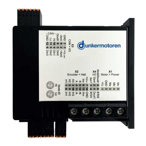
Page 31: Terminal Assignment
6.2.2 Terminal Assignment 6.2.2 Anschlussbelegung Terminal X1.1 (electronic supply) is in- Klemme X1.1 (Spannungsversorgung ternally not connected with terminal X2.1 Elektronik) ist intern nicht mit Klemme (power supply). X2.1 (Spannungsversorgung Leistung) verbunden. Terminal X1.2 (Ground for power supp- Klemme X1.2 (Masse Leistung) ist intern ly) is internally connected with terminal mit Klemme X2.14 (Masse Elektronik) X2.14 (Ground for electronic supply) verbunden. By assembling the cables consider the Achten Sie bei der Konfektionierung aller skinning lenght of the particular connec- Leitungen auf die Abisolierlänge für die tors . -
Page 32: Hall Sensors/Encoders & Analog And Digital Inputs And Outputs
6.2.4 Hall Sensors/Encoders & analog and digital 6.2.4 Hallsensoren/Encoder & analoge und digitale inputs and outputs Ein- und Ausgänge assignment/ Pinbelegung Terminal/ Beschreibung/ Signal direction/ Klemme Description Signalrichtung Hallsensor signal 1/ X2.1 input/Eingang Hallsensorsignal 1 Hallsensor signal 2/ X2.2 input/Eingang ... -
Page 33: Connection Brushless Motor
Connection brushless motor Anschluss bürstenloser Motor Page/Seite 33 / 83 Version 2.0 / 28-02-2024 BGE 6060 A... -
Page 34: Connection Hall Sensors
Connection Hall sensors Anschluss Hallsensoren Only with brushless DC motors! Nur bei bürstenlosen Gleichstrommotoren optional optional /H3 optional Connection encoder Anschluss Encoder Spur A ext. Encoder Spur B Index Spur /A optional Spur /B optional Spur /Inx optional Page/Seite 34 / 83 BGE 6060 A Version 2.0 / 28-02-2024... -
Page 35: Connection Power Supply / Grounding
Connection power supply / Grounding Anschluss Spannungsversorgung / Erdung 9 ... 60V Connection electronics / Controller enabling Anschluss Elektronik / Reglerfreigabe (STO) (STO) For the BGE 6060A with STO functionality (part number Verwenden Sie für die BGE 6060A mit STO-Funktionalität 88740.01260), use the corresponding safety manual. -
Page 36: Connection Can Interface
Connection CAN interface Anschluss CAN Schnittstelle 7 8 9 10 11 12 CAN High CAN Low CAN Gnd Galvanically isolated, no seperate power supply needed. Galvanisch getrennt, keine separate Spannungsversor- gung erforderlich. When using the Motion starter kit (SNR 27573.35616), Bei Verwendung des Motion Starterkits (SNR note the following lead assignment: 27573.35616) gilt die folgende Litzen-Zuordnung: White: CAN high Weiß: CAN high Green: CAN low Grün: CAN low Black: CAN GND Schwarz: CAN GND Heat sink mounting Kühlkörperanbindung Use 355,6 x 355,6 x 2 mm (14“ x 14“ x 0.08“) aluminium Aluminiumplatte 355,6 x 355,6 x 2 mm (14“ x 14“ x 0.08“) plate or heat sink with equivalent thermal characteristic oder einen Kühlkörper mit gleichwertigen thermischen... -
Page 37: Block Diagram
6.10 Block diagram 6.10 Blockschaltbild Page/Seite 37 / 83 Version 2.0 / 28-02-2024 BGE 6060 A... -
Page 38: Emc Compliant Installation
6.11 EMC compliant installation 6.11 EMV-konforme Installation NOTICE ACHTUNG High-frequency interference Hochfrequente Störungen (radio interference) (Funkstörungen) If the products are not installed accordingly the instruc- Wird das Produkt nicht entsprechend den Anweisun- tions in operation, it can create Interference with radio gen in Betrieb genommen und verwendet, kann es zu transmission. - Page 39 Only use 60°C or 75°C copper Verwenden Sie nur 60°C oder 75°C conduits. Kupferleitungen. Erden Sie den Antrieb/die Regelelektronik (Funktions- Earth the motor/controller (functional earth „FE“). erde“FE“). Shield all connecting cables or use shielded connec- Schirmen Sie alle Verbindungskabel ab oder verwen- ting cables and connect them at both ends to „FE“.
-
Page 40: Functional Earth
6.11.1 Functional Earth 6.11.1 Funktionserde Note that protection from influence by Beachten Sie, dass ohne Erdung des electromagnetic fields is not provided if Schirms ein Schutz gegen Beeinflus- the shield is not earthed. sung durch elektromagnetische Felder nicht gegeben ist. Cable shields must be low-inductive earthed on both Kabelschirme sind niederinduktiv beidseitig zu erden. -
Page 41: Status Leds
6.13 Status LEDs 6.13 Status LEDs Blinken Flashing/ = ON = OFF Color/ Status Bedeutung Meaning/ Farbe Power supply is missing/ Versorgungsspannung fehlt LED 0 green/ Normal operation/ grün Normalbetrieb „Power“ green/ Bootloader mode (lack of firmware)/ grün Bootloader Modus (keine Firmware) CANopen Operational state (PDOs active)/ CANopen Operational Zustand (PDOs aktiv) LED 1 yellow/... -
Page 42: Digital Inputs
6.14 Digital inputs 6.14 Digitale Eingänge Description/ Beschreibung Number of inputs/ Anzahl Eingänge Input voltage, low (UIN low)/ -30 ... +5 Eingangsspannung Low (UIN low) Input voltage, high (UIN high)/ 8 ... 30 Eingangsspannung High (UIN high) Maximum frequency/ about 500 / ca. 500 Maximale Frequenz 6.15 Digital outputs 6.15 Digitale Ausgänge Description/ Beschreibung Number of output/ Anzahl Ausgänge Type/... -
Page 43: Analog Inputs
6.16 Analog Inputs 6.16 Analoge Eingänge Description/ Beschreibung Number of inputs/ Anzahl Eingänge 1 differential / differentiell Type/ 1 x single ended Measurement range/ -10 ... +10 Messbereich Resolution/ 12 bit Auflösung 6.17 Inputs for hall sensors 6.17 Eingänge für Hallsensoren Description/ Beschreibung Number of inputs/ Anzahl Eingänge Type/ open collector single ended Inputs/ H1, H2, H3/ /H1, /H2, /H3... -
Page 44: Auxiliary Power Supply
6.19 Auxiliary power supply 6.19 Hilfsspannungen Description/ Beschreibung Power supplies for Hall sensors and encoders/Versorgungsspannung für Hallsensoren und Encoder output voltag/ 5 ±5% Ausgangsspannung Maximum load/ Maximale Belastung 6.20 Input/Putput Ratings 6.20 Eingangs- und Ausgangswerte Input ratings: DC Voltage Isolated Power Source/ Eingangswerte: Gleichspannung Isolierte Stromquelle Base Frequency PWM (kHz)/ Circuit/ Duty Cycle/... -
Page 45: Commissioning
Commissioning Inbetriebnahme When the power supply has been connected, the unit can Ist die Spannungsversorgung hergestellt, kann das Gerät be switched on. The module is then open to access from eingeschaltet werden. Nun kann der softwareseitige Zugriff the software side. auf das Modul erfolgen. For the connection between the Positioning Controller Für die Verbindung zwischen Positioniersteuerung unmd and a PC you need the appropriate Stater Kit with adapter PC benötigen Sie das passende Starter Kit mit Adapterka- cable and software. bel und Software Stand alone operation Stand alone Betrieb For commissioning the software „Drive Assistant“... -
Page 46: Description Of Main Window
7.1.4 Description of main window 7.1.4 Beschreibung des Hauptfensters In the group fields the configurable modules are shown. In den Gruppenfeldern werden die konfigurierbaren Modi Double clicking on a project makes it appear in a new angzeigt. Durch Doppelklicken auf einen gewählten Modus window. erscheint in einem neuen Fenster die gewählte Projektvor- lage. 7.1.3 Project Window 7.1.3 Projektfenster By clicking on the symbol help information is displayed. Eine Hilfe zu den jeweiligen Projektfenstern erhalten Sie durch Anklicken des jeweiligen Symbols. Page/Seite 46 / 83 BGE 6060 A Version 2.0 / 28-02-2024... -
Page 47: Short Description Of Pi Modules
7.1.5 Short description of PI modules 7.1.5 Kurzbeschreibung PI Module 7.1.5.1 PI 100 Positioning module „Standard“ 7.1.5.1 PI 100 Positioning module „Standard“ Reference or limit switch Referenz- oder Limitschalter Switch OFF Schalter AUS Switch ON Schalter EIN Function Funktion Clear error and STOP Fehler quittieren und STOP Start Homing Homing starten... -
Page 48: Pi 110 Positioning Module „Stepper
7.1.5.2 PI 110 Positioning module „Stepper“ 7.1.5.2 PI 110 Positioning module „Stepper“ Reference or limit switch Referenz- oder Limitschalter Switch OFF Schalter AUS Switch ON Schalter EIN Function Funktion Clear error and STOP Fehler quittieren und STOP Start homing Homing starten Position 1 (positive) Position 1 (positiv) Position-1 (negative) Position-1 (negativ) -
Page 49: Pi 120 Positioning Module „Left-Right
7.1.5.3 PI 120 Positioning module „Left-Right“ 7.1.5.3 PI 120 Positioning module „Left-Right“ Reference or limit switch Referenz- oder Limitschalter Switch OFF Schalter AUS Switch ON Schalter EIN Funktion Funktion Fehler quittieren und STOP Fehler quittieren und STOP Homing starten Homing starten Position 1 Position 1 Position 2 Position 2 To facilitate the binary entries, the fifth digital input is used... -
Page 50: Pi 130 Positioning Module „Modulo
7.1.5.4 PI 130 Positioning module „Modulo“ 7.1.5.4 PI 130 Positioning module „Modulo“ Reference or limit switch Referenz- oder Limitschalter Switch OFF Schalter AUS Switch ON Schalter EIN Function Funktion Clear error and STOP Fehler quittieren und STOP Start homing Homing starten Position 1 Position 1 Position 2 Position 2... -
Page 51: Pi 140 Positioning Module „Complete Positioning Command
7.1.5.5 PI 140 Positioning module 7.1.5.6 PI 140 Positioning module „Complete positioning command“ „Complete positioning command“ Only limited functionality: Nur eingeschränkt möglich: Only position 1 and 2 can be used. OUT 2 is not available. Nur Position en 1 und 2 können genutzt werden. Es ste- hen keine Ausgänge zur Verfügung. Reference or limit switch Referenz- oder Limitschalter Switch OFF Schalter AUS Switch ON Schalter EIN Funktion Funktion Fehler quittieren und STOP Fehler quittieren und STOP Homing starten Homing starten... - Page 52 7.1.5.5 PI 150 Positioning module 7.1.5.6 PI 150 Positioning module „Positioning by event“ „Positioning by event“ Only limited functionality: Nur eingeschränkt möglich: Only one fixed speed or analog speed setting is possible. Nur eine Festdrehzahl bzw. analoge Drehzahleinstellung möglich. Function Funktion Not used Nicht belegt Rising edge: Start CCW Steigende Flanke: Start CCW 0 ->1 0 ->1 - counter clockwise - gegen den Uhrzeigersinn Rising edge: Start CW Steigende Flanke: Start CW 0 ->1 0 ->1 - clockwise...
-
Page 53: Pi 200 Velocity Module „Velocity Mode Standard
7.1.5.7 PI 200 Velocity module 7.1.5.7 PI 200 Velocity module „Velocity mode standard“ „Velocity mode standard“ Only limited functionality: Nur eingeschränkt möglich: Only one fixed speed or analog speed setting is possible. Nur eine Festdrehzahl bzw. analoge Drehzahleinstellung möglich. Function Funktion Schnellstop, deaktivieren und Fehler Quick STOP, disable and clear error quittieren CCW – gegen den Uhrzeigersinn CCW - counter clockwise CW – im Uhrzeigersinn CW – clockwise STOP, aktivieren und Fehler quittieren STOP, enable and clear error Function Funktion Velocity 1 Geschwindigkeit 1 Velocity 2 Geschwindigkeit 2 Velocity 3 Geschwindigkeit 3 Alternatively you can set the target velocity by the analo- Alternativ kann die Geschwindigkeits-auswahl über den gue input. -
Page 54: Pi 200 Velocity Module „Velocity Mode Multi
7.1.5.8 PI 201 Velocity module 7.1.5.8 PI 200 Velocity module „Velocity mode multi“ „Velocity mode multi“ Only limited functionality: Nur eingeschränkt möglich: Only two fixed speeds or analog speed setting is possible. Nur zwei Festdrehzahlen bzw. analoge Drehzahleinstel- lung möglich. Function Funktion Schnellstop, deaktivieren und Fehler Quick STOP, disable and clear error quittieren CCW – gegen den Uhrzeigersinn CCW - counter clockwise CW – im Uhrzeigersinn CW – clockwise Stop, aktivieren und Fehler quittieren STOP, enable and clear error Function Funktion Velocity 1 Geschwindigkeit 1 Velocity 2 Geschwindigkeit 2 Velocity 3 Geschwindigkeit 3 Velocity 4 Geschwindigkeit 4 Velocity 5... -
Page 55: Pi 300 Current Module „Current Mode Standard
7.1.5.9 PI 300 Current Module 7.1.5.9 PI 300 Current Module „Current mode standard“ „Current mode standard“ Only limited functionality: Nur eingeschränkt möglich: Only one current setpoint or analog current value setpoint Nur eine feste Stromsollwert- bzw. analoge Stromwertvor- is possible. gabe möglich. Function Funktion Schnellstop, deaktivieren und Fehler Quick STOP, disable and clear error quittieren CCW – gegen den Uhrzeigersinn CCW - counter clockwise CW – im Uhrzeigersinn CW – clockwise Stop, aktivieren und Fehler quittieren STOP, enable and clear error Function Funktion... -
Page 56: Pi 301 Current Module „Current Mode Multi
7.1.5.10 PI 301 Current Module 7.1.5.10 PI 301 Current Module „Current mode multi“ „Current mode multi“ Only limited functionality: Nur eingeschränkt möglich: Only one current setpoint or analog current value setpoint Nur eine feste Stromsollwert- bzw. analoge Stromwertvor- is possible. gabe möglich. Function Funktion Schnellstop, deaktivieren und Fehler Quick STOP, disable and clear error quittieren CCW – gegen den Uhrzeigersinn CCW - counter clockwise CW – im Uhrzeigersinn CW – clockwise Stop, aktivieren und Fehler quittieren STOP, enable and clear error Function Funktion... -
Page 57: Slave In Canopen
Slave in CANopen Slave in CANopen The slave in CANopen network requires the „Motion Start Das Slave in CANopen Netzwerk benötigt das „Motion Kit“ with the software „mPLC“. Start Kit“ mit der Software „mPLC“. (not included) (nicht im Lieferumfang enthalten) For commissioning of the controller a CAN-master is ne- Zur Inbetriebnahme des Reglers ist ein CAN-Master cessary. Following options are available: erforderlich. Hierzu stehen die folgenden Varianten zur Verfügung: » a PC / Laptop and the miCAN-USB are needed »... -
Page 58: Mplc Introduction
7.2.2 mPLC introduction 7.2.2 PLC Einführung With the mPLC control program, Dunkermotoren provides Mit dem Steuerungsprogramm mPLC bietet Dunkermo- a comprehnsive software tool with which it is possible to toren ein umfangreiches Softwaretool, mit dem es möglich extensively configure the controller. Via the CAN interface, ist verschiedene Regler umfangreich zu konfigurieren. the software establishes a connection with the controller Über die CAN-Schnittstelle stellt die Software die Ver- and controls it with the individual configuration. bindung mit dem Regler her und steuert diesen mit der individuellen Konfiguration. -
Page 59: Mplc System Requirements
7.2.4 mPLC system requirements 7.2.4 mPLC Systemvoraussetzungen Operation system: Windows 2000, Windows XP Home, Betriebssystem: Windows 2000, Windows XP Home, Windows XP Pro, Windows Vista, Windows 7. The in- Windows XP Pro, Windows Vista, Windows 7. Sie können stallation files for mPLC can be loaded from the provided die Installationsdateien für mPLC von der mitgelieferten CD-ROM. CD-ROM installieren. 7.2.5 Installation of the Software mPLC 7.2.5 Installation der Software mPLC Administrator privileges are necessary for the installation. Zur Installation des Programms benötigen Sie Admin- The installation menu starts automatically after insertion of Rechte. Nach dem Einlegen der CD-ROM öfftent sich das CD-ROM. Installationsmenü automatisch. Alternatively you can open the file install the file install.htm Alternativ können Sie mit der Datei install.htm im Win- in the windows explorer to open the intallation menu. The dows-Explorer das Installationsmenü öffnen. Sie werden... -
Page 60: Mplc Control Center
If the message „INFO: CAN-USB - not found“ is indica- Sollte im Statusfeld die Meldung „INFO: CAN-USB - not found“ stehen, wurde kein CAN-USB Adapter erkannt. ted in the status field, no CAN_USB adapter was identi- fied. In this case please examine if the CAN-USB adapter Bitte prüfen Sie, ob der CAN-USB Adapter mit der entspre- is connected to the correct PC interface and if the power- chenden Schnittstelle am PC verbunden ist und ob die LED glows. -
Page 61: Python Script
7.2.8 Python Script 7.2.8 Python Script The start of mPLC opens the „Control Center“ in which you Beim Starten von mPLC öffnet sich das „Control Center“ in can select inter alia „Python Script“. welchem Sie u.a. „Python Script“ anwählen können. Python is a programming language which comprises se- Python ist ein Programmiersprache, die mehrere Ptrom- veral programming paradigmas. This supports the object mierparadigmen umfasst. So wird die objekctorientiere, orientated, aspect-orientated and functional programming. aspektorientierte und funktionale Programmierung unter- stützt. Menu bar Menüleiste All settings (CAN-objects, -variabales) can be stored in the Alle Einstellungen (CAN-Objekte, -Variablen) könnn in... - Page 62 In the menu „Script“ you can control the syntax and start Im Menü „Script“ können Sie den Syntax prüfen und das the script. Script starten. In addition there is the possibility to pause and to continue Desweiteren besteht die Möglichkeit das Script anzuhalten the script as well as to stop it. und fortzufahren sowie es zu beenden. Check syntax Syntax prüfen Run script Script starten Pause script Script anhalten Continue script Script fortsetzen Stop script Script stoppen In the menu „Python“ the handbook and the documentati- Das Menü „Python“ beinhaltet das Handbuch und die on of the modules are included. Dokumentation der Module. Open „Python Prompt“ Öffnen „Python Prompt“ Open console Öffnen Konsole Open handbook Öffnen Handbuch Open handbook in HTML version Öffnen Handbuch in HTML Version...
- Page 63 Assistance Hilfsmittel „Baude_rate“ „Baude_rate“ A new field appears in which the Baud-rate can be se- Es erscheint ein neues Feld in dem die Baud_rate gewählt lected (20k, 50k, 100k, 125k, 500k, 800k, 1000k) and set (20k, 50k, 100k, 125k, 500k, 800k, 1000k) und gesetzt („Set Baud_rate“). This modification is only effective after werden kann („Set Baud_rate“). Die Änderung wird erst the motor is switched off and on. mit dem Aus- und Einschalten des Motors wirksam. „Firmware“ „Firmware“ Please contact the manufacturer for a firmware update! Bitte wenden Sie sich für ein Firmware-Uptade an den Hersteller! Each motor type has its own firmware Jeder Motortyp hat seine eigene which must fit to the appropriate motor! Firmware, die zu dem entsprechenden Motor passen muss! „Node_ID“ „Node_ID“ A new field in which the node address can be modified in Es erscheint ein neues Feld in dem die Knotenadresse im the range of 1 to 127 („Set Node_ID). This modification is Bereich von 1 ... 127 geändert werden kann („Set Node_ only effective after the motor is switched off and on.
-
Page 64: Can Monitor
7.2.9 CAN monitor 7.2.9 CAN Monitor The CAN monitor is a program to observe and send CAN Der CAN Monitor ist ein Programm, um CAN-Nachrichten messages. Therewith CAN transmissions can be contol- zu beobachten und zu senden. Damit lässt sich eine led, supervised, displayed and interpreted. CAN-Übertragung steuern, überwachen, darstellen und interpretieren. For CAN objects you can use both CANopen PDO as well Als CAN-Objekte können sowohl CAN-Open PDO (als as SDO which can be recorded then. auch SDO verwendet werden, die dann aufgezeichnet werden können. On the CD you can find some example files for the CAN Auf der CD finden Sie einige Beispiel-Dateien zum CAN monitor. Monitor. Menu bar Menüleiste All settings (CAN-objects, -variabales) can be stored in Alle Einstellungen (CAN-Objekte, -Variablen) können in form of a parameter file (*.cm) Form einer Parameterdatei (.*cm) gespeichert werden. Generate a new empty file Erzeugen einer neuen leeren Datei Open an existing file Öffnen einer bestehenden Datei... - Page 65 CAN variables can be edited as follows: CAN-Variable können wie folgt bearbeitet werden: Generate a new CAN variable Erzeugen CAN-Variable Edit the selected CAN variable Bearbeiten der ausgewählten CAN-Variablen Copy the selected variable Kopieren der ausgewählten CAN-Variablen Delete the selected variable Löschen der ausgewählten CAN-Variablen The order of CAN objects and variables can be changed Die Reihenfolge von CAN-Objekten und -Variablen kann with this functions: mit diesen Funktionen verändert werden: Move the element one line up Element eine Zeile nach oben schieben Move the element one line down Element eine Zeile nach unten schieben...
-
Page 66: Configuration
7.2.10 Konfiguration 7.2.10 Configuration The CAN-USB adapter can be configurated with „Hard- Hier kann unter „Hardware“ der CAN-USB-Adapter konfi- ware“. Normally the configuration is set automatically. If guriert werden. Im Allgemeinen geschieht dieses automa- the baud rate of the controller should be changed, also tisch. Sollte jedoch die Baud_rate des Reglers geändert the mPLC settings have to be adapted. If the CAN-USB werden, so muss sie auch für mPLC angepasst werden. adapter is attached, its status is indicated green. Ist der CAN-USB-Adapter angeschlossen, wird sein Status mit grün angezeicht Page/Seite 66 / 83 BGE 6060 A Version 2.0 / 28-02-2024... - Page 67 Note regarding the serial adapter respectively the serial Hinweis zum seriellen Adapter bzw. zur seriellen Schnitt- interface: stelle: If your PC / laptop has a no serial interface, you should Sollte Ihr PC / Laptop über keine serielle Schnittstelle ver- disable this function here. fügen, sollten Sie diese Funktion hier deaktivieren. Page/Seite 67 / 83 Version 2.0 / 28-02-2024 BGE 6060 A...
-
Page 68: Objekte
7.2.10.1 Objects 7.2.10.1 Objekte In dem Bereich „CAN Objects“ werden alle angelegten In the area „CAN objects“ all created CAN objects are CAN Objekte aufgelistet. Es werden folgende Parame- listed. The following parameters are shown column by ter der Objekte spaltenweise angezeigt: column: •Name Free-defineable name of the object •Name freibestimmbarer Name des Objektes •ID •ID CAN identification number of the object CAN Identifikationsnummer des Objektes •Type Object type: •Typ Art des Objektes: •RX receive object •RX Empfangsobjekt •TX send object •TX Sendeobjekt •RX PDO CANopen PDO •RX PDO CANopen PDO receive object Empfangsobjekt •TX PDO CANopen PDO •TX PDO... - Page 69 •uint32 unsigned integer 32 bit •uint32 unsigned integer 32 bit - 32 bit whole number without signs - 32 bit ganze Zahl ohne Vorzeichen • float Fließkomma-Zahl •float floating point number •Byte(s) byte assignment of the variable inside •Byte(s) Bytebelegung der Variable innerhalb der the CAN message CAN Nachricht •Factor (a) multiplier •Factor (a) Multiplikator •Offset (b) constant, which is added to a result (a*x) •Offset (b) Konstante, die zu dem Ergebnis (a * x) addiert wird •Filter MIN minimum value of the filter •Filter MIN Minimumwert des Filters...
-
Page 70: Anlegen Von Can-Objekten
7.2.10.3 Set up CAN objects 7.2.10.3 Anlegen von CAN-Objekten Zum Anlegen von CAN-Objekten können die gelben The yellow symbols can be used to setup CAN objects Symbole verwendet werden (s.o.). (see above). Mit dem ersten „New CAN-Objekt“ erzeugen Sie ein With the first “New CAN object” you generate a new neues Objekt, mit dem nächsten „Edit CAN-Object“ neh- object, with the next “Edit CAN object” you can modify, men Sie Änderungen vor, das dritte „Copy CAN-Object“ the third “Copy CAN object” duplicates and the last one dupliziert und das letzte löscht ein Objekt. deletes an object. Zum Anlegen eines SDOs wählen Sie unter „CANopen“ For generating a service data object please select via zunächst „SDO“ an, vergeben dann einen Namen („Obj. “CANopen” at first “SDO”, assign then a name (“Obj. Name“) und zuletzt die Knotenadresse „Node-ID“. Die Name”) and lastly a node address “Node-ID” The rest of restlichen Felder werden nicht benötigt. the fields are not required. Zum Anlegen eines PDOs gibt es zwei Wege: There are 2 possibilities for disposing PDOs: Nach „New CAN-Object“ kann sofort die COB-ID ein- After “New CAN object” the COB ID can be registered getragen werden (ohne SDO oder PDO auszuwählen). -
Page 71: Anlegen Von Can-Variablen
7.2.10.4 Anlegen von CAN-Variablen 7.2.10.4 Set up CAN variables CAN object type PDO CAN Objekt Type PDO With this variable single bytes of a PDO can be selec- Mit dieser Variable lassen sich aus einem PDO einzelne ted, filtered and scaled. The following parameters can Bytes selektieren, filtern und skalieren. Folgende Para- be set: meter können eingestellt werden: •VarName Free-assignable name of the object •VarName freibestimmbarer Name der Variable •Data type Data type of the variable •Datentyp Datentyp der Variable •bool Boolean – “0” or “1”... - Page 72 •Filter active •Filter (Filter Active) • Switching on or switching off the value filter • Einschalten oder Ausschalten des Wertfilters • Kind of the filter (Prohibitive) • Art des Filters (Prohibitive) • Not activated: Only values are Nicht aktiviert: Es werden nur Werte collected/ recorded, which are inside of the erfasst / protokolliert, die innerhalb der boundary. Min <= Y <= max Grenzen liegen. min <= Y <= max • Activated: Only values are • Aktiviert: Es werden nur Werte collected/ recorded, which are outside of the erfasst / protokolliert, die außerhalb der boundary. Y < min or > max Grenzen liegen. Y < min oder Y > max •...
-
Page 73: Senden / Empfangen
7.2.10.5 Transmit / Receive 7.2.10.5 Senden / Empfangen With the CAN monitor CAN messages can be transmitted Mit dem CAN Monitor können CAN-Nachrichten gesendet (PC => controller) and received (PC<= controller). There- (PC => Regler) und empfangen (PC <= Regler) werden. fore the required object or the required variable must be Dazu muss das gewünschte Objekt oder die gewünschte selected: Variable angewählt werden: * Receive. with „CTRL + R“ or * Empfangen: oder mit „CTRL + R“ *Transmit : with „CTRL + T“ or * Senden: oder mit „CTRL +T“ 7.2.10.6 Recording 7.2.10.6 Aufzeichnen Received messages can be displayed and recorded in a Empfangene Nachrichten können in einem separaten separate window (see menu „View“) Fenster dargestellt und aufgezeichnet werden (s. Menü „View“) Display received CAN objects Anzeigen der empfangenen CAN-Objekte Display recieived CAN variables Anzeigen der empfangenen CAN-Variablen Recording CAN objects Aufzeichnen von CAN-Objekten... - Page 74 The received objects can be stored as Die empfangenen Objekte lassen sich als “Log_RX-objects” „Log – RX-Objects“-Datei speichern (bzw. speichern un- These files are in ASCII format (*.Igo). Therefore these ter). Diese Dateien (*.lgo) haben ASCII-Format und kön- files can be opened and edited in every other text editor. nen daher nicht nur mit mPLC sondern auch mit jedem anderen Text-Editor geöffnet und bearbeitet werden. •“Safe List” •„Save List“ Stores the list Speichert die Liste •“Safe List as…” Stores the list under an •„Save List as …“ Speichert die Liste unter other name anderem Namen •“Delete List” Deletes the complete list •„Delete List“...
-
Page 75: Can Master Of Other Manufacturers
The received objects can be stored as Die empfangenen Objekte lassen sich als “Log_RX-Variables”. „Log – RX-Objects“-Datei speichern (bzw. speichern un- These files are in ASCII format (*.Igo). Therefore these ter). Diese Dateien (*.lgo) haben ASCII-Format und kön- files can be opened and edited in every other text editor. nen daher nicht nur mit mPLC sondern auch mit jedem anderen Text-Editor geöffnet und bearbeitet werden. •“Safe List” Stores the list •“Safe List as…” •„Save List“ Stores the list under an other Speichert die Liste name •„Save List as …“ Speichert die Liste unter •“Delete List” Deletes the complete list anderem Namen •“Set Time Origin”... -
Page 76: Communication Settings
7.2.12 Communication settings 7.2.12 Kommunikationseinstellungen Please connect the controller separately (not in the CAN Der Regler ist einzeln (nicht im CAN-Netzwerk) an einen network) to a master (PC). For the initial communication Master (PC) anzuschließen. Die Kommunikationspara- the parameters must be set to the factory settings of the meter am Master müssen auf die Werkseinstellungen des controller. The use of the provided CAN monitor is recom- Reglers eingestellt werden, damit die erste Kommunikati- mended. on aufgebaut werden kann. Es wird die Verwendung des zur Verfügung stehenden CAN-Monitors oder das mPLC empfohlen. -
Page 77: Herstellerspezifische Variante
7.2.12.2 Manufacturer specific variant 7.2.12.2 Herstellerspezifische Variante This variant is more convenient for initial commissioning. Diese Variante ist für die Erstinbetriebnahme besser geeignet. Use of mPLC Verwendung von mPLC •Open and starting the example Script •Öffnen und Starten des Beispiels Scripts “Nodeld_Scan.py”, „Node-Id_Scan.py“, in order to find the node address of the controller um die Knotenadresse des Reglers zu finden •Open the example Script •Öffnen des Beispiels Scripts “Nodeld_Change.py”, „Node-Id_Change.py“, there enter the desired node address and dort die gewünschte Knotenadresse eintragen start this Script. -
Page 78: Est Programs And Other Assistance
* Changing Baud_rate * Ändern der Baud_rate The changes become only effective af- Die Änderungen werden erst nach ter switching off and on the controller! Aus- und Einschalten des Reglers wirksam! When changing the Baudrate the mas- Beim Ändern der Baudrate ist der Mas- ter also has to be configured accor- ter ebenfalls entsprechend zu konfigu- dingly! rieren! 7.2.13 est programs and other assistance 7.2.13 Testprogramme und weitere Hilfsmittel The Starter Kit CD provides more examples e.g. motor Auf der Starter Kit CD finden Sie weitere Beispiele z. B. configuring, position control, spee and current controll, Motorkonfigurierung, Positioniersteuerung, Geschwin- PDO mapping. These can be implemented directly via digkeits- und Stromregelung, PDO-Mapping. Diese kön- mPLC. In addtion you find also appropriate CAN monitor nen unter mPLC direkt ausgeführt werden. Dazu finden files in order to control the CAN bus. Sie auch entsprechende CAN-Monitor-Dateien um den CAN-Bus zu kontrollieren. -
Page 79: Maintenance
Maintenance Wartung The basic safety notes must be read Vor der Wartung sind unbedingt die grundlegenden Sicherheitshinweise zu and observed before maintenance. Non-observation may cause danger to lesen und zu beachten. Eine Nichtbeachtung kann zu Gefahren people or damage to the product. für Personen oder Beschädigungen am Produkt führen. -
Page 80: Decommissioning And Disposal
Allmendstrasse 11 Allmendstrasse 11 D-79848 Bonndorf D-79848 Bonndorf Phone: +49 (0) 77 03/930-0 Telefon: 0 77 03/930-0 Fax: +49 (0) 77 03/930-210 Fax: 0 77 03/930-210 Email: info.dunkermotoren@ametek.com E-Mail: info.dunkermotoren@ametek.com Page/Seite 80 / 83 BGE 6060 A Version 2.0 / 28-02-2024... -
Page 81: Imprint
D-79848 Bonndorf D-79848 Bonndorf Phone: +49 (0) 77 03/930-0 Telefon: 0 77 03/930-0 Fax: +49 (0) 77 03/930-210 Fax: 0 77 03/930-210 E-Mail: info.dunkermotoren@ametek.com E-Mail: info.dunkermotoren@ametek.com © Dunkermotoren GmbH, 2024 © Dunkermotoren GmbH, 2024 All rights reserved. Alle Rechte vorbehalten. - Page 82 Dunkermotoren GmbH | Allmendstr. 11 | D-79848 Bonndorf/ Schwarzwald Phone +49 (0) 7703 930-0 | Fax +49 (0) 7703 930-210/ 212 | info.dunkermotoren@ametek.com...
Need help?
Do you have a question about the dunkermotoren BGE 6060 A and is the answer not in the manual?
Questions and answers