Sign In
Upload
Manuals
Brands
Ametek Manuals
DC Drives
Dunkermotoren BGE 6060 A EC
Ametek Dunkermotoren BGE 6060 A EC Manuals
Manuals and User Guides for Ametek Dunkermotoren BGE 6060 A EC. We have
3
Ametek Dunkermotoren BGE 6060 A EC manuals available for free PDF download: Translation Of The Original Function And Connection Manual, Operation Manual
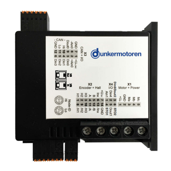
Ametek Dunkermotoren BGE 6060 A EC Translation Of The Original Function And Connection Manual (82 pages)
Brand:
Ametek
| Category:
Measuring Instruments
| Size: 5.73 MB
Table of Contents
Table of Contents
2
About this Documentation
6
Zu dieser Dokumentation
6
Liability and Warranty
7
Target Group
7
Safety Notes
7
Haftung und Gewährleistung
7
Zielgruppe
7
Sicherheitshinweise
7
Icons
8
Hazard Signs
8
Piktogramme
8
Gefahrenzeichen
8
EC/EU Declaration of Conformity
9
Directives
9
EG/EU-Konformitätserklärung
9
Richtlinien
9
Safety Notes
10
Intended Use
10
Expected Misuse
10
Sicherheitshinweise
10
Bestimmungsgemäße Verwendung
10
Vorhersehbarer Fehlgebrauch
10
Basic Safety Notes
11
Safety Notes for Staff
11
Grundlegende Sicherheitshinweise
11
Sicherheitshinweise für Personal
11
Safety Notes Concerning Operating Phases
12
Transport
12
Installation
12
Cleaning
12
Maintenance/Repair
12
Sicherheitshinweise zu Betriebsphasen
12
Reinigung
12
Wartung/Reparatur
12
Environmentally Compatible Disposal
13
Notes Concerning Special Hazard Types
13
Electrical Energy/Electromagnetic Safety
13
Mechanical Safety
13
Umweltgerecht Entsorgen
13
Hinweise auf Besondere Gefahrenarten
13
Elektrische Energie/Elektromagnetische Sicherheit
13
Mechanische Sicherheit
13
Transport and Storage
14
Transport und Lagerung
14
Product Description
15
Series
15
Starter Kit (Accessory)
15
Produktbeschreibung
15
Baureihe
15
Starter Kit (Zubehör)
15
Types of Operation
16
Slave in Canopen Networks
16
Betriebsarten
16
Slave in Canopen Netzwerken
16
Stand-Alone Operation at Stored Running Profile
17
Stand-Alone Betrieb mit Gespeichertem Fahrprofil
17
Protective Functions
18
Solid State Short Circuit Protection
18
Motor Overload Protection
18
Branch Circuit Protection
18
Field Wiring Terminals
18
Schutzfunktionen
18
Halbleiterkurzschlussschutz
18
Motorüberlastungsschutz
18
Schutz des Abzweigstromkreises
18
Feldverdrahtungsklemmen
18
Technical Data, Accessories
19
Product Specification
19
Technische Daten, Zubehör
19
Produktspezifikation
19
General Features
20
Allgemeine Eigenschaften
20
Current Characteristics
21
Stromkennlinien
21
Dimensions
22
Maßzeichnung
22
Installation
23
Mechanical Assembly
24
Mechanische Montage
24
Electrical Assembly
25
Elektrische Montage
25
Power Supply Connection
30
Anschluss Spannungsversorgung
30
Terminal Assignment
31
Power Supply and Motor Connections
31
Anschlussbelegung
31
Versorgungsspannung und Motoranschluss
31
Hall Sensors/Encoders & Analog and Digital Inputs and Outputs
32
Hallsensoren/Encoder & Analoge und Digitale Ein- und Ausgänge
32
Connection Brushless Motor
33
Anschluss Bürstenloser Motor
33
Connection Hall Sensors
34
Connection Encoder
34
Anschluss Hallsensoren
34
Anschluss Encoder
34
Connection Power Supply / Grounding
35
Connection Electronics / Controller Enabling (STO)
35
Anschluss Spannungsversorgung / Erdung
35
Anschluss Elektronik / Reglerfreigabe (STO)
35
Connection CAN Interface
36
Heat Sink Mounting
36
Anschluss CAN Schnittstelle
36
Kühlkörperanbindung
36
Block Diagram
37
Blockschaltbild
37
EMC Compliant Installation
38
EMV-Konforme Installation
38
Functional Earth
40
Protective Earth Conductor
40
Protective Grounding
40
Funktionserde
40
Schutzleiter
40
Schutzerdung
40
Status Leds
41
Digital Inputs
42
Digital Outputs
42
Digitale Eingänge
42
Digitale Ausgänge
42
Analog Inputs
43
Inputs for Hall Sensors
43
Inputs for Encoders
43
Analoge Eingänge
43
Eingänge für Hallsensoren
43
Eingänge für Encoder
43
Auxiliary Power Supply
44
Input/Putput Ratings
44
Hilfsspannungen
44
Eingangs- und Ausgangswerte
44
Commissioning
45
Stand Alone Operation
45
System Requirements
45
Installation of Software Drive Assistant
45
Inbetriebnahme
45
Stand Alone Betrieb
45
Systemvoraussetzungen
45
Installation Software Drive Assistant
45
Description of Main Window
46
Beschreibung des Hauptfensters
46
Project Window
46
Projektfenster
46
Short Description of PI Modules
47
PI 100 Positioning Module „Standard
47
Kurzbeschreibung PI Module
47
PI 110 Positioning Module „Stepper
48
PI 120 Positioning Module „Left-Right
49
PI 130 Positioning Module „Modulo
50
PI 140 Positioning Module „Complete Positioning Command
51
PI 140 Positioning Module
51
Complete Positioning Command
51
PI 200 Velocity Module „Velocity Mode Standard
53
PI 200 Velocity Module
53
PI 200 Velocity Module „Velocity Mode Multi
54
Velocity Mode Multi
54
PI 300 Current Module „Current Mode Standard
55
PI 301 Current Module „Current Mode Multi
56
Slave in Canopen
57
Hardware Controller
57
Hardware Regler
57
Mplc Introduction
58
Documentation
58
PLC Einführung
58
Dokumentation
58
Mplc System Requirements
59
Installation of the Software Mplc
59
Installation CAN-USB Adapter
59
Mplc Systemvoraussetzungen
59
Installation der Software Mplc
59
Mplc Control Center
60
Python Script
61
CAN Monitor
64
Configuration
66
Konfiguration
66
Objekte
68
Objekt- / SDO-Variable
68
Anlegen von CAN-Objekten
70
Anlegen von CAN-Variablen
71
Senden / Empfangen
73
Aufzeichnen
73
CAN Master of Other Manufacturers
75
CAN-Master anderer Hersteller
75
Communication Settings
76
Standardvariante -LMT Dienste
76
Kommunikationseinstellungen
76
Herstellerspezifische Variante
77
Est Programs and Other Assistance
78
Testprogramme und Weitere Hilfsmittel
78
Maintenance
79
Wartung
79
Decommissioning and Disposal
80
Service and Support
80
Außerbetriebnahme und Entsorgung
80
Service und Support
80
Imprint
81
Impressum
81
Advertisement
Ametek Dunkermotoren BGE 6060 A EC Operation Manual (65 pages)
Brand:
Ametek
| Category:
Controller
| Size: 3.96 MB
Table of Contents
Table of Contents
2
About this Document
6
Über dieses Dokument
6
General Description
7
Series
7
Allgemeine Beschreibung
7
Baureihe
7
Explanation of Terms Used
8
Begriffserklärung
8
Proper Use
9
Standards and Guidelines
9
Bestimmungsgemäße Verwendung
9
Zertifikate/ Konformitäten
9
Safety Instructions
10
Sicherheitshinweise
10
Technical Data, Accessories
11
General Performance Data
11
Technische Daten, Zubehör
11
Allgemeine Leistungsdaten
11
General Features
12
Allgemeine Eigenschaften
12
Current Characteristics
13
Stromkennlinien
13
Dimensions
14
Starter Kit (Accessory)
14
Maßzeichnung
14
Starter Kit (Zubehör)
14
Types of Operation
15
Slave in Canopen Networks
15
Betriebsarten
15
Slave in Canopen Netzwerken
15
Stand-Alone Operation at Stored Running
16
Profile
16
Stand-Alone Betrieb mit Gespeichertem
16
Fahrprofil
16
Installation
17
Terminal Assignment
18
Anschlussbelegung
18
Power Supply and Motor Connections
19
Versorgungsspannung und Motoranschluss
19
Inputs and Outputs
20
Hallsensoren/Encoder & Analoge und Digi- Tale Ein- und Ausgänge
20
EMC-Compliant Installation
21
EMV-Gerechte Installation
21
Connection Brushless Motor
22
Connection Brushed Motor
22
Anschluss Bürstenloser Motor
22
Anschluss Bürstenbehafteter Motor
22
Connection Hall Sensors
23
Connection Encoder
23
Anschluss Hallsensoren
23
Anschluss Encoder
23
Connection Power Supply / Grounding
24
Connection Electronics / Controller Enabling
24
(Sto)
24
Anschluss Spannungsversorgung / Erdung
24
Anschluss Elektronik / Reglerfreigabe (STO)
24
Connection CAN Interface
25
Block Diagram
25
Anschluss CAN Schnittstelle
25
Blockschaltbild
25
Digital Inputs
26
Digital Outputs
26
Digitale Eingänge
26
Digitale Ausgänge
26
Analog Inputs
27
Inputs for Hall Sensors
27
Inputs for Encoders
27
Auxiliary Power Supply
27
Analoge Eingänge
27
Eingänge für Hallsensoren
27
Eingänge für Encoder
27
Hilfsspannungen
27
Status Leds
28
Maintenance & Service & Support
29
Maintenance, Taking out of Service and Dis- Posal
29
Service & Support
29
Declaration of Conformity
29
Wartung & Service & Support
29
Wartung, Außerbetriebsetzung und Entsor- Gung
29
Konformitätserklärung
29
Commissioning
30
Stand Alone Operation
30
System Requirements
30
Installation of Software Drive Assistant
30
Inbetriebnahme
30
Stand Alone Betrieb
30
Systemvoraussetzungen
30
Installation Software Drive Assistant
30
Description of Main Window
31
Project Window
31
Beschreibung des Hauptfensters
31
Projektfenster
31
Short Description of PI Modules
32
PI 100 Positioning Module „Standard
32
Kurzbeschreibung PI Module
32
PI 110 Positioning Module „Stepper
33
PI 120 Positioning Module „Left-Right
34
PI 130 Positioning Module „Modulo
35
PI 140 Positioning Module
36
Complete Positioning Command
36
PI 150 Positioning Module
37
Positioning by Event
37
PI 200 Velocity Module
38
Velocity Mode Standard
38
PI 201 Velocity Module
39
Velocity Mode Multi
39
PI 200 Velocity Module
39
PI 300 Current Module
40
Current Mode Standard
40
PI 301 Current Module
41
Current Mode Multi
41
Slave in Canopen
42
Hardware Controller
42
Hardware Regler
42
Mplc Introduction
43
Documentation
43
Mplc Einführung
43
Dokumentation
43
Mplc System Requirements
44
Installation of the Software Mplc
44
Installation CAN-USB Adapter
44
Mplc Systemvoraussetzungen
44
Installation der Software Mplc
44
Mplc Control Center
45
Python Script
46
CAN Monitor
49
Configuration
51
Konfiguration
51
Objects
53
Objects / SDO-Variable
53
Objekte
53
Objekt- / SDO-Variable
53
Set up CAN Objects
55
Anlegen von CAN-Objekten
55
Set up CAN Variables
56
Anlegen von CAN-Variablen
56
Transmit / Receive
58
Recording
58
Senden / Empfangen
58
Aufzeichnen
58
CAN Master of Other Manufacturers
60
CAN-Master anderer Hersteller
60
Communication Settings
61
Standard Variant - LMT Services
61
Kommunikationseinstellungen
61
Standardvariante -LMT Dienste
61
Manufacturer Specific Variant
62
Herstellerspezifische Variante
62
Test Programs and Other Assistance
63
Testprogramme und Weitere Hilfsmittel
63
Ametek Dunkermotoren BGE 6060 A EC Operation Manual (32 pages)
Brand:
Ametek
| Category:
DC Drives
| Size: 2.31 MB
Table of Contents
English
2
Table of Contents
2
About this Document
5
Über dieses Dokument
5
General Description
6
Series
6
Explanation of Terms Used
6
Allgemeine Beschreibung
6
Baureihe
6
Begriffserklärung
6
Service Data Object (SDO)
7
Servicedatenobjekt (SDO)
7
Process Data Object (PDO)
8
Proper Use
8
Prozessdatenobjekt (PDO)
8
Bestimmungsgemäße Verwendung
8
Current Characteristics
12
Stromkennlinien
12
Starter Kit (Option)
13
Types of Operation
14
Dunkermotoren Specific Control „Quick-Start
14
Operation Modes According to Cia DS402 (en 61800-7-201:2008)
14
Betriebsarten
14
Dunkermotoren Spezifische Ansteuerung „Quick-Start
14
Betriebsmodi nach Cia DS402 (en 61800-7- 201:2008)
14
Twincat System
15
Power Supply and Motor Connections
18
Hall Sensors/Encoders & Analog and Digital
18
Inputs and Outputs
18
Versorgungsspannung und Motoranschluss
18
Hallsensoren/Encoder & Analoge und Digi- Tale Ein- und Ausgänge
18
EMC-Compliant Installation
20
EMV-Gerechte Installation
20
Connection Brushless Motor
21
Anschluss Bürstenloser Motor
21
Connection Brushed Motor
21
Anschluss Bürstenbehafteter Motor
21
Connection Hall Sensors
22
Connection Encoder
22
Anschluss Hallsensoren
22
Anschluss Encoder
22
German
7
Ethercat Specific Explanations
7
Canopen over Ethercat (Coe)
7
Ethercat Spezifische Begriffe
7
Standards and Guidelines
8
Zertifikate/ Konformitäten
8
Safety Instructions
9
Sicherheitshinweise
9
Technical Data, Accessories
10
General Performance Data
10
Technische Daten, Zubehör
10
Allgemeine Leistungsdaten
10
General Features
11
Allgemeine Eigenschaften
11
Dimensions
13
Maßzeichnung
13
Non Supported Functions
15
Nicht Unterstützte Funktionen
15
Installation
16
Terminal Assignment
17
Anschlussbelegung
17
Connection Power Supply / Grounding
23
Connection Electronics / Controller Enabling
23
Anschluss Spannungsversorgung / Erdung
23
Anschluss Elektronik / Reglerfreigabe
23
Connection CAN Interface (Only for Service)
24
Block Diagram
24
Anschluss CAN Schnittstelle (nur für Service)
24
Blockschaltbild
24
Digital Inputs
25
Digital Outputs
25
Digitale Eingänge
25
Digitale Ausgänge
25
Analog Inputs
26
Inputs for Hall Sensors
26
Inputs for Encoders
26
Auxiliary Power Supply
26
Analoge Eingänge
26
Eingänge für Hallsensoren
26
Eingänge für Encoder
26
Hilfsspannungen
26
Status Leds
27
Commissioning
29
ESI File
29
Documentation
29
Inbetriebnahme
29
ESI-Datei
29
Dokumentationen
29
Maintenance & Service & Support
30
Maintenance, Taking out of Service and Dis- Posal
30
Service & Support
30
Declaration of Conformity
30
Wartung & Service & Support
30
Wartung, Außerbetriebsetzung und Entsor- Gung
30
Konformitätserklärung
30
Advertisement
Advertisement
Related Products
Ametek dunkermotoren BG 95x40 dPro CO
Ametek dunkermotoren BG 95x80 dPro CO
Ametek dunkermotoren BG 95x120 dPro CO
Ametek Dunkermotoren BGE 6005 A
Ametek dunkermotoren BGE 6010 A
Ametek dunkermotoren BGE 6015 A
Ametek dunkermotoren BGE 6030 A
Ametek Dunkermotoren BGE 5510 dPro IO/CO
Ametek dunkermotoren BG 65x75 dMove
Ametek dunkermotoren BG 45 dCore
Ametek Categories
Measuring Instruments
Test Equipment
Power Supply
Controller
Laboratory Equipment
More Ametek Manuals
Login
Sign In
OR
Sign in with Facebook
Sign in with Google
Upload manual
Upload from disk
Upload from URL