
Subscribe to Our Youtube Channel
Related Manuals for Daikin VRV Aurora RXLQ-TATJU Series


Summary of Contents for Daikin VRV Aurora RXLQ-TATJU Series
- Page 1 SiUS341802EC Service Manual Aurora Series 208/230 V: RXLQ72-240TA/TB Series 460 V: RXLQ72-240TA/TB Series 575 V: RXLQ72-240TA/TB Series 575 V: RXYQ72-384TA Series Heat Pump 60 Hz...
- Page 2 SiUS341802EC Introduction ..................1 1. Safety Cautions................... 2 1.1 Warnings and Cautions Regarding Safety of Workers......... 2 1.2 Warnings and Cautions Regarding Safety of Users........4 2. Icons Used ....................7 3. Revision History ..................8 Part 1 General Information ............... 9 1.
- Page 3 SiUS341802EC 2.3 Wireless Remote Controller ............... 67 3. Main/Sub Setting..................68 3.1 BRC1E73 ....................68 3.2 BRC1H71W....................70 3.3 When Wireless Remote Controller is Used Together......... 72 4. Address Setting for Wireless Remote Controller........73 5. Centralized Control Group No. Setting............75 5.1 BRC1E73 ....................
- Page 4 SiUS341802EC 8. Other Control...................108 8.1 Backup Operation..................108 8.2 Demand Operation ................... 108 8.3 Heating Operation Prohibition ..............108 9. Outline of Control (Indoor Unit) ...............109 9.1 Operation Flowchart ................. 109 9.2 Set Temperature and Control Target Temperature........113 9.3 Remote Controller Thermistor ..............115 9.4 Thermostat Control...................
- Page 5 SiUS341802EC Part 6 Service Diagnosis ............... 205 1. Symptom-based Troubleshooting ............208 1.1 Indoor Unit Overall ................... 208 1.2 With Gas Furnace ..................211 1.3 Gas Furnace Lockout Reset..............211 1.4 With Infrared Presence/Floor Sensor ............212 2. Error Code via Remote Controller............213 2.1 BRC1E73 ....................
- Page 6 SiUS341802EC 3.37 Compressor Motor Lock ................289 3.38 Compressor Damage Alarm..............291 3.39 Outdoor Fan Motor Abnormality ............... 293 3.40 Electronic Expansion Valve Coil Abnormality........... 298 3.41 Discharge Pipe Temperature Abnormality ..........299 3.42 Wet Alarm....................301 3.43 Refrigerant Overcharged................303 3.44 Harness Abnormality (between Outdoor Unit Main PCB and Inverter PCB)......................
- Page 7 SiUS341802EC 3.79 Climate Talk Communication System Combination Error (After Initial Setting for Communication Completes)............ 366 4. Check ......................367 4.1 High Pressure Check ................367 4.2 Low Pressure Check ................368 4.3 Superheat Operation Check..............370 4.4 Power Transistor Check ................372 4.5 Refrigerant Overcharge Check..............
- Page 8 SiUS341802EC Introduction 1. Safety Cautions................... 2 1.1 Warnings and Cautions Regarding Safety of Workers......... 2 1.2 Warnings and Cautions Regarding Safety of Users........4 2. Icons Used ....................7 3. Revision History ..................8 Introduction...
- Page 9 SiUS341802EC Safety Cautions 1. Safety Cautions Be sure to read the following safety cautions before conducting repair work. After the repair work is complete, be sure to conduct a test operation to ensure that the equipment operates normally, and explain the cautions for operating the product to the customer. This manual is for the person in charge of maintenance and...
- Page 10 Safety Cautions SiUS341802EC Warning Be sure to discharge the capacitor completely before conducting repair work. The step-up capacitor supplies high-voltage electricity to the electrical components of the outdoor unit. A charged capacitor may cause an electrical shock. Do not turn the air conditioner on or off by plugging in or unplugging the power cable.
- Page 11 SiUS341802EC Safety Cautions Caution Be sure to check that the refrigerating cycle section has cooled down enough before conducting repair work. Working on the unit when the refrigerating cycle section is hot may cause burns. Conduct welding work in a well-ventilated place. Using the welder in an enclosed room may cause oxygen deficiency.
- Page 12 Safety Cautions SiUS341802EC Warning Do not mix air or gas other than the specified refrigerant (R-32 / R-410A / R-22) in the refrigerant system. If air enters the refrigerant system, an excessively high pressure results, causing equipment damage and injury. If the refrigerant gas leaks, be sure to locate the leaking point and repair it before charging the refrigerant.
- Page 13 SiUS341802EC Safety Cautions Caution Be sure to measure insulation resistance after the repair, and make sure that the resistance is 1 M or higher. Faulty insulation may cause an electrical shock. Be sure to check the drainage of the indoor unit after the repair. Faulty drainage may cause water to enter the room and wet the furniture and floor.
- Page 14 Icons Used SiUS341802EC 2. Icons Used The following icons are used to attract the attention of the reader to specific information. Icon Type of Description Information Warning Warning is used when there is danger of personal injury. Warning Caution Caution is used when there is danger that the reader, Caution through incorrect manipulation, may damage equipment, lose data, get an unexpected result or have to restart (part...
- Page 15 SiUS341802EC Revision History 3. Revision History Month / Year Version Revised contents 04 / 2018 SiUS341802E First edition Model addition: 03 / 2020 SiUS341802EA RXLQ72-240TATJA, RXLQ72-240TAYDA, RXLQ72-240TAYCA, RXYQ72-384TAYCA Model addition: 03 / 2022 SiUS341802EB FXZQ05-18TBVJU, FXUQ18-36PAVJU, BRC1H71W Model addition: RXLQ72-240TBTJA, RXLQ72-240TBYDA, RXLQ72-240TBYCA, FXFQ07-54AAVJU, 01 / 2024 SiUS341802EC FXSQ05-54TBVJU, FXMQ15-54TBVJU, FXMQ72/96TAVJU, FXTQ09-60TBVJUA,...
-
Page 16: Table Of Contents
SiUS341802EC Part 1 General Information 1. Model Names ....................10 1.1 Outdoor Unit ....................10 1.2 Indoor Unit....................12 1.3 Air Treatment Equipment ................12 2. External Appearance................. 13 2.1 Outdoor Unit ....................13 2.2 Indoor Unit....................14 2.3 Air Treatment Equipment ................15 3. -
Page 17: Model Names
SiUS341802EC Model Names 1. Model Names Outdoor Unit Capacity Range (ton) Power supply, Standard Capacity Index 72TA 96TA 120TA 144TA — 192TA — Aurora Series RXLQ Heat Pump 72TB 96TB 120TB 144TB — 192TB — Standard Series RXYQ 72TA 96TA 120TA 144TA 168TA... - Page 18 Model Names SiUS341802EC Aurora Series RXLQ-TAYDU, RXLQ-TAYDA, RXLQ-TBYDA (460 V) Model name RXLQ72TAYDU RXLQ96TAYDU RXLQ120TAYDU RXLQ144TAYDU RXLQ192TAYDU RXLQ240TAYDU Outdoor unit 1 RXLQ72TAYDU RXLQ96TAYDU RXLQ120TAYDU RXLQ72TAYDU RXLQ96TAYDU RXLQ120TAYDU Outdoor unit 2 — — — RXLQ72TAYDU RXLQ96TAYDU RXLQ120TAYDU Model name RXLQ72TAYDA RXLQ96TAYDA RXLQ120TAYDA RXLQ144TAYDA RXLQ192TAYDA RXLQ240TAYDA Outdoor unit 1 RXLQ72TAYDA...
-
Page 19: Indoor Unit
SiUS341802EC Model Names Indoor Unit Capacity range (ton) 1.25 Power supply, Standard Capacity index Ceiling mounted — 07AA 09AA 12AA 15AA 18AA — 24AA 30AA 36AA — 48AA 54AA — — — cassette (Round flow with — — — — —... -
Page 20: External Appearance
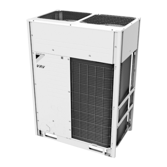
External Appearance SiUS341802EC 2. External Appearance Outdoor Unit Single Outdoor Unit RXLQ72/96/120TATJU RXLQ72/96/120TATJA RXLQ72/96/120TBTJA RXYQ72/96/120/144/168TAYCU RXLQ72/96/120TAYDU RXLQ72/96/120TAYDA RXLQ72/96/120TBYDA RXYQ72/96/120/144/168TAYCA RXLQ72/96/120TAYCU RXLQ72/96/120TAYCA RXLQ72/96/120TBYCA Double Outdoor Unit RXLQ144/192/240TATJU RXLQ144/192/240TATJA RXLQ144/192/240TBTJA RXYQ192/216/240/264/288/312/336TAYCU RXLQ144/192/240TAYDU RXLQ144/192/240TAYDA RXLQ144/192/240TBYDA RXYQ192/216/240/264/288/312/336TAYCA RXLQ144/192/240TAYCU RXLQ144/192/240TAYCA RXLQ144/192/240TBYCA Triple Outdoor Unit RXYQ360/384TAYCU RXYQ360/384TAYCA Part 1 General Information... -
Page 21: Indoor Unit
SiUS341802EC External Appearance Indoor Unit Ceiling mounted cassette (Round flow with sensing) type Slim ceiling mounted duct type FXFQ-AA FXDQ-M Shown with BYCQ54EEFU Ceiling mounted cassette (Round flow with sensing) type MSP concealed ducted type FXFQ-T FXSQ-TA FXSQ-TB Shown with BYCQ125B-W1 Ceiling mounted cassette (Round flow) type Ceiling mounted duct type (Middle and high static pressure) FXFQ-P... -
Page 22: Air Treatment Equipment
External Appearance SiUS341802EC Wall mounted type Air handling unit FXAQ-P FXTQ-TA FXTQ-TB Floor standing type Cased coil unit FXLQ-M CXTQ-TA Concealed floor standing type FXNQ-M — Air Treatment Equipment Outdoor-air processing unit Energy recovery ventilator (VAM series) FXMQ-MF VAM-G Part 1 General Information... -
Page 23: Combination Of Outdoor Units
SiUS341802EC Combination of Outdoor Units 3. Combination of Outdoor Units RXLQ-TA, RXLQ-TB System capacity Module Number Outdoor unit multi Model name of units connection piping kit 1 RXLQ72TA RXLQ72TB RXLQ96TA 10.0 — RXLQ96TB RXLQ120TA 12.5 RXLQ120TB RXLQ144TA 15.0 ... -
Page 24: Capacity Range
And the connection ratio must not exceed 100%. It is permitted to use a maximum connection ratio of 130% in some circumstances – please contact your 3. local Daikin representative for further details. RXYQ-TA Max. connection ratio... -
Page 25: Outdoor Unit Combinations
SiUS341802EC Capacity Range Outdoor Unit Combinations RXLQ-TA, RXLQ-TB Capacity range (Ton) 72TA 96TA 120TA 144TA 192TA 240TA RXLQ 72TB 96TB 120TB 144TB 192TB 240TB Max. number of connectable indoor units Total capacity index of indoor 51-93 68-124 84-156 101-187 135-249 168-312 units to be (144) -
Page 26: Specifications
Specifications SiUS341802EC 5. Specifications RXLQ-TA, RXLQ-TB Model name RXLQ72TATJU(A) RXLQ96TATJU(A) RXLQ120TATJU(A) Power supply 3 phase, 208/230 V, 60 Hz 3 phase, 208/230 V, 60 Hz 3 phase, 208/230 V, 60 Hz 1 Cooling capacity Nominal 72,000 (21.1) 96,000 (28.1) 120,000 (35.2) Btu/h (kW) Rated... - Page 27 SiUS341802EC Specifications Model name (Combination unit) RXLQ144TATJU(A) RXLQ192TATJU(A) RXLQ240TATJU(A) RXLQ72TATJU(A) RXLQ96TATJU(A) RXLQ120TATJU(A) Model name (Independent unit) RXLQ72TATJU(A) RXLQ96TATJU(A) RXLQ120TATJU(A) Power supply 3 phase, 208/230 V, 60 Hz 3 phase, 208/230 V, 60 Hz 3 phase, 208/230 V, 60 Hz 1 Cooling capacity Nominal 144,000 (42.2) 192,000 (56.3)
- Page 28 Specifications SiUS341802EC Model name RXLQ72TBTJA RXLQ96TBTJA RXLQ120TBTJA Power supply 3 phase, 208/230 V, 60 Hz 3 phase, 208/230 V, 60 Hz 3 phase, 208/230 V, 60 Hz 1 Cooling capacity Nominal 72,000 (21.1) 96,000 (28.1) 119,000 (34.9) Btu/h (kW) Rated 69,000 (20.2) 92,000 (27.0) 114,000 (33.4)
- Page 29 SiUS341802EC Specifications Model name (Combination unit) RXLQ144TBTJA RXLQ192TBTJA RXLQ240TBTJA RXLQ72TBTJA RXLQ96TBTJA RXLQ120TBTJA Model name (Independent unit) RXLQ72TBTJA RXLQ96TBTJA RXLQ120TBTJA Power supply 3 phase, 208/230 V, 60 Hz 3 phase, 208/230 V, 60 Hz 3 phase, 208/230 V, 60 Hz 1 Cooling capacity Nominal 144,000 (42.2) 192,000 (56.3)
- Page 30 Specifications SiUS341802EC Model name RXLQ72TAYDU(A) RXLQ96TAYDU(A) RXLQ120TAYDU(A) Power supply 3 phase, 460 V, 60 Hz 3 phase, 460 V, 60 Hz 3 phase, 460 V, 60 Hz 1 Cooling capacity Nominal 72,000 (21.1) 96,000 (28.1) 120,000 (35.2) Btu/h (kW) Rated 69,000 (20.2) 92,000 (27.0) 114,000 (33.4)
- Page 31 SiUS341802EC Specifications Model name (Combination unit) RXLQ144TAYDU(A) RXLQ192TAYDU(A) RXLQ240TAYDU(A) RXLQ72TAYDU(A) RXLQ96TAYDU(A) RXLQ120TAYDU(A) Model name (Independent unit) RXLQ72TAYDU(A) RXLQ96TAYDU(A) RXLQ120TAYDU(A) Power supply 3 phase, 460 V, 60 Hz 3 phase, 460 V, 60 Hz 3 phase, 460 V, 60 Hz 1 Cooling capacity Nominal 144,000 (42.2) 192,000 (56.3)
- Page 32 Specifications SiUS341802EC Model name RXLQ72TBYDA RXLQ96TBYDA RXLQ120TBYDA Power supply 3 phase, 460 V, 60 Hz 3 phase, 460 V, 60 Hz 3 phase, 460 V, 60 Hz 1 Cooling capacity Nominal 72,000 (21.1) 96,000 (28.1) 119,000 (34.9) Btu/h (kW) Rated 69,000 (20.2) 92,000 (27.0) 114,000 (33.4)
- Page 33 SiUS341802EC Specifications Model name (Combination unit) RXLQ144TBYDA RXLQ192TBYDA RXLQ240TBYDA RXLQ72TBYDA RXLQ96TBYDA RXLQ120TBYDA Model name (Independent unit) RXLQ72TBYDA RXLQ96TBYDA RXLQ120TBYDA Power supply 3 phase, 460 V, 60 Hz 3 phase, 460 V, 60 Hz 3 phase, 460 V, 60 Hz 1 Cooling capacity Nominal 144,000 (42.2) 192,000 (56.3)
- Page 34 Specifications SiUS341802EC Model name RXLQ72TAYCU(A) RXLQ96TAYCU(A) RXLQ120TAYCU(A) Power supply 3 phase, 575 V, 60 Hz 3 phase, 575 V, 60 Hz 3 phase, 575 V, 60 Hz 1 Cooling capacity Nominal 72,000 (21.1) 96,000 (28.1) 120,000 (35.2) Btu/h (kW) Rated 69,000 (20.2) 92,000 (27.0) 114,000 (33.4)
- Page 35 SiUS341802EC Specifications Model name (Combination unit) RXLQ144TAYCU(A) RXLQ192TAYCU(A) RXLQ240TAYCU(A) RXLQ72TAYCU(A) RXLQ96TAYCU(A) RXLQ120TAYCU(A) Model name (Independent unit) RXLQ72TAYCU(A) RXLQ96TAYCU(A) RXLQ120TAYCU(A) Power supply 3 phase, 575 V, 60 Hz 3 phase, 575 V, 60 Hz 3 phase, 575 V, 60 Hz 1 Cooling capacity Nominal 144,000 (42.2) 192,000 (56.3)
- Page 36 Specifications SiUS341802EC Model name RXLQ72TBYCA RXLQ96TBYCA RXLQ120TBYCA Power supply 3 phase, 575 V, 60 Hz 3 phase, 575 V, 60 Hz 3 phase, 575 V, 60 Hz 1 Cooling capacity Nominal 72,000 (21.1) 96,000 (28.1) 119,000 (34.9) Btu/h (kW) Rated 69,000 (20.2) 92,000 (27.0) 114,000 (33.4)
- Page 37 SiUS341802EC Specifications Model name (Combination unit) RXLQ144TBYCA RXLQ192TBYCA RXLQ240TBYCA RXLQ72TBYCA RXLQ96TBYCA RXLQ120TBYCA Model name (Independent unit) RXLQ72TBYCA RXLQ96TBYCA RXLQ120TBYCA Power supply 3 phase, 575 V, 60 Hz 3 phase, 575 V, 60 Hz 3 phase, 575 V, 60 Hz 1 Cooling capacity Nominal 144,000 (42.2) 192,000 (56.3)
-
Page 38: Rxyq-Ta
Specifications SiUS341802EC RXYQ-TA Model name RXYQ72TAYCU(A) RXYQ96TAYCU(A) RXYQ120TAYCU(A) Power supply 3 phase, 575 V, 60 Hz 3 phase, 575 V, 60 Hz 3 phase, 575 V, 60 Hz 1 Cooling capacity Nominal 72,000 (21.1) 96,000 (28.1) 120,000 (35.2) Btu/h (kW) Rated 69,000 (20.2) 92,000 (27.0) - Page 39 SiUS341802EC Specifications Model name RXYQ144TAYCU(A) RXYQ168TAYCU(A) Power supply 3 phase, 575 V, 60 Hz 3 phase, 575 V, 60 Hz 1 Cooling capacity Nominal 144,000 (42.2) 158,000 (46.3) Btu/h (kW) Rated 138,000 (40.4) 150,000 (44.0) 2 Heating capacity Nominal 162,000 (47.5) 188,000 (55.1) Btu/h (kW)
- Page 40 Specifications SiUS341802EC Model name (Combination unit) RXYQ192TAYCU(A) RXYQ216TAYCU(A) RXYQ240TAYCU(A) RXYQ96TAYCU(A) RXYQ96TAYCU(A) RXYQ120TAYCU(A) Model name (Independent unit) RXYQ96TAYCU(A) RXYQ120TAYCU(A) RXYQ120TAYCU(A) Power supply 3 phase, 575 V, 60 Hz 3 phase, 575 V, 60 Hz 3 phase, 575 V, 60 Hz 1 Cooling capacity Nominal 192,000 (56.3) 216,000 (63.3)
- Page 41 SiUS341802EC Specifications Model name (Combination unit) RXYQ264TAYCU(A) RXYQ288TAYCU(A) RXYQ312TAYCU(A) RXYQ120TAYCU(A) RXYQ144TAYCU(A) RXYQ144TAYCU(A) Model name (Independent unit) RXYQ144TAYCU(A) RXYQ144TAYCU(A) RXYQ168TAYCU(A) Power supply 3 phase, 575 V, 60 Hz 3 phase, 575 V, 60 Hz 3 phase, 575 V, 60 Hz 1 Cooling capacity Nominal 264,000 (77.4) 288,000 (84.4)
- Page 42 Specifications SiUS341802EC Model name (Combination unit) RXYQ336TAYCU(A) RXYQ360TAYCU(A) RXYQ384TAYCU(A) RXYQ120TAYCU(A) RXYQ120TAYCU(A) RXYQ168TAYCU(A) Model name (Independent unit) RXYQ120TAYCU(A) RXYQ120TAYCU(A) RXYQ168TAYCU(A) RXYQ120TAYCU(A) RXYQ144TAYCU(A) Power supply 3 phase, 575 V, 60 Hz 3 phase, 575 V, 60 Hz 3 phase, 575 V, 60 Hz 1 Cooling capacity Nominal 324,000 (95.0)
- Page 43 SiUS341802EC Part 2 Refrigerant Circuit 1. Refrigerant Circuit (Piping Diagrams) ............37 1.1 Outdoor Unit ....................37 1.2 Indoor Unit....................41 1.3 Outdoor-Air Processing Unit............... 44 2. Functional Parts Layout ................45 2.1 RXLQ72TA, RXLQ72TB, RXYQ72-120TA..........45 2.2 RXLQ96/120TA, RXLQ96/120TB, RXYQ144/168TA......... 48 3.
-
Page 44: Refrigerant Circuit Part
Refrigerant Circuit (Piping Diagrams) SiUS341802EC 1. Refrigerant Circuit (Piping Diagrams) Outdoor Unit No. in Electric piping Name Function symbol diagram Compressor Compressor is operated in multi-steps according to Te and Tc. Fan motor Because the system is an air heat exchange type, the fan rotation speed is varied by using inverter. - Page 45 SiUS341802EC Refrigerant Circuit (Piping Diagrams) No. in Electric piping Name Function symbol diagram Thermistor (Deicer) Used to detect liquid pipe temperature of air heat exchanger. (33) R11T Used to make judgements on defrost operation. Thermistor Used to detect suction pipe temperature of compressor. (34) R12T (Compressor suction)
- Page 46 Refrigerant Circuit (Piping Diagrams) SiUS341802EC RXLQ72TA, RXLQ72TB, RXYQ72-120TA Part 2 Refrigerant Circuit...
- Page 47 SiUS341802EC Refrigerant Circuit (Piping Diagrams) RXLQ96/120TA, RXLQ96/120TB, RXYQ144/168TA Part 2 Refrigerant Circuit...
-
Page 48: Indoor Unit
Refrigerant Circuit (Piping Diagrams) SiUS341802EC Indoor Unit Symbol Except No. in FXMQ-PB FXTQ-TA piping Name Function FXTQ-TA FXMQ-PB FXTQ-TB diagram FXTQ-TB CXTQ-TA CXTQ-TA Electronic expansion valve Used for gas superheating degree control while in cooling or subcooling degree control while in heating. - Page 49 SiUS341802EC Refrigerant Circuit (Piping Diagrams) FXUQ-P, FXEQ-P, FXSQ-TA, FXMQ-M, FXAQ-P, FXLQ-M, FXZQ-M FXNQ-M Gas piping connection port Gas piping connection port Indoor heat exchanger Indoor heat exchanger Liquid piping connection port Liquid piping connection port Filter Filter C: 4D040157B Filter Filter C: 4D034245S FXSQ-TB, FXMQ-TB...
- Page 50 Refrigerant Circuit (Piping Diagrams) SiUS341802EC FXTQ-TA, FXTQ-TB FXMQ-TA C: 3D117738B C: 4D068194 CXTQ-TA Gas piping connection port Indoor heat exchanger Liquid piping connection port Filter Filter Part 2 Refrigerant Circuit...
-
Page 51: Outdoor-Air Processing Unit
SiUS341802EC Refrigerant Circuit (Piping Diagrams) Outdoor-Air Processing Unit FXMQ48/72/96MFVJU* Gas pipe connection port Heat exchanger Filter Capillary tube Distributor Solenoid valve Liquid pipe connection port Check valve Filter Filter Electronic expansion valve C: 4D018650D No. in piping Electric symbol Name Function diagram Electronic expansion valve... -
Page 52: Functional Parts Layout
Functional Parts Layout SiUS341802EC 2. Functional Parts Layout RXLQ72TA, RXLQ72TB, RXYQ72-120TA Plane View Electronic expansion valve High pressure sensor (Refrigerant cooling) (S1NPH) (Y5E) Solenoid valve (Liquid shutoff) Electronic expansion valve (Y3S) (Subcooling heat exchanger) Solenoid valve (Y2E) (Hot gas bypass) (Y2S) Four way valve (Heat exchanger upper) - Page 53 SiUS341802EC Functional Parts Layout Part B Thermistor (Receiver gas purge) (R13T) Electronic expansion valve (Receiver gas purge) (Y7E) Part A detail Thermistor (Leak detection) Thermistor (Subcooling injection) (R15T) (R16T) Electronic expansion valve (Leak detection) (Y6E) Thermistor (Receiver inlet) (R3T) Thermistor (Heat exchanger liquid upper) (R4T) Thermistor...
- Page 54 Functional Parts Layout SiUS341802EC Back View of Electrical Box Refer to the illustration below for the location of the reactor thermistor (R71T, R72T) for RXLQ72TATJU, RXLQ72TATJA, RXLQ72TBTJA. Reactor thermistor (R72T) Reactor thermistor (R71T) 1P476849F Part 2 Refrigerant Circuit...
-
Page 55: Rxlq96/120Ta, Rxlq96/120Tb, Rxyq144/168Ta
SiUS341802EC Functional Parts Layout RXLQ96/120TA, RXLQ96/120TB, RXYQ144/168TA Plane View High pressure sensor Electronic expansion valve (S1NPH) (Refrigerant cooling) Solenoid valve (Liquid shutoff) (Y5E) (Y3S) Electronic expansion valve (Subcooling heat exchanger) Solenoid valve (Y2E) (Hot gas bypass) Four way valve (Y2S) (Heat exchanger upper) Solenoid valve (OS oil return) (Y6S) - Page 56 Functional Parts Layout SiUS341802EC Electronic expansion valve (Receiver gas purge) (Y7E) Part B Thermistor (Receiver gas purge) (R13T) Part A detail Thermistor (Leak detection) Thermistor (Subcooling injection) (R15T) (R16T) Electronic expansion valve (Leak detection) (Y6E) Thermistor (Receiver inlet) (R3T) Thermistor (Heat exchanger liquid upper) (R4T) Thermistor...
-
Page 57: Refrigerant Flow For Each Operation Mode
SiUS341802EC Refrigerant Flow for Each Operation Mode 3. Refrigerant Flow for Each Operation Mode Cooling Operation High temperature, high pressure gas High temperature, high pressure liquid Low temperature, low pressure gas Low temperature, low pressure liquid Stop valve(With service φ5/16in.(7.9mm)flare connection) Check valve Check valve Filter... -
Page 58: Heating Operation
Refrigerant Flow for Each Operation Mode SiUS341802EC Heating Operation High temperature, high pressure gas High temperature, high pressure liquid Low temperature, low pressure gas Low temperature, low pressure liquid Stop valve(With service φ5/16in.(7.9mm)flare connection) Check valve Check valve Filter Liquid pipe Check valve Check valve... -
Page 59: Cooling Oil Return Operation
SiUS341802EC Refrigerant Flow for Each Operation Mode Cooling Oil Return Operation High temperature, high pressure gas High temperature, high pressure liquid Low temperature, low pressure gas Low temperature, low pressure liquid Stop valve(With service φ5/16in.(7.9mm)flare connection) Check valve Check valve Filter Liquid pipe... -
Page 60: Defrost Heating Oil Return Operation
Refrigerant Flow for Each Operation Mode SiUS341802EC Defrost Heating Oil Return Operation High temperature, high pressure gas High temperature, high pressure liquid Low temperature, low pressure gas Low temperature, low pressure liquid Stop valve(With service φ5/16in.(7.9mm)flare connection) Check valve Check valve Filter Liquid pipe... - Page 61 SiUS341802EC Part 3 Remote Controller 1. Applicable Models ..................55 2. Names and Functions ................56 2.1 BRC1E73 ....................56 2.2 BRC1H71W....................59 2.3 Wireless Remote Controller ............... 67 3. Main/Sub Setting..................68 3.1 BRC1E73 ....................68 3.2 BRC1H71W....................70 3.3 When Wireless Remote Controller is Used Together......... 72 4.
-
Page 62: Applicable Models
Applicable Models SiUS341802EC 1. Applicable Models Wired remote controller Series Wireless remote controller Navigation Madoka FXFQ-AA FXFQ-T — FXFQ-P BRC082A42W (for BYFQ60C3W1W) FXZQ-TA BRC082A42S (for BYFQ60C3W1S) BRC082A41W (for BYFQ60B3W1) BRC082A42W (for BYFQ60C3W2W) FXZQ-TB BRC082A41W (for BYFQ60B3W1) FXZQ-M BRC7E830 BRC1E73 FXUQ-P FXUQ-PA —... -
Page 63: Names And Functions
SiUS341802EC Names and Functions 2. Names and Functions BRC1E73 1. Operation mode selector button 11. LCD (with backlight) 4. Up button 5. Down button 6. Right button 7. Left button 9. Operation lamp 8. On/Off button 3. Menu/OK button 10. Cancel button 2. - Page 64 Names and Functions SiUS341802EC 4. Up button Used to raise the setpoint. The item above the current selection will be highlighted. (The highlighted items will be scrolled continuously when the button is continuously pressed.) Used to change the selected item. 5.
- Page 65 SiUS341802EC Names and Functions Service Check Function <Main Menu> Main Menu • Airflow Direction Airflow Direction • Individual Airflow Direction Individual Airflow Direction • Ventilation Ventilation • Schedule Schedule • Off Timer Off Timer • Celsius / Fahrenheit Celsius / Fahrenheit •...
-
Page 66: Brc1H71W
Names and Functions SiUS341802EC BRC1H71W 2.2.1 Button Locations and Descriptions ON/OFF button • Press this button to turn on the system. • Press this button again to turn off the system. b Status indicator (LED) • During operation, the light ring around the display lights up blue/red/green. Lights up blue: Operating, Blinks red: Error is occurring, Lights up/blinks green: Bluetooth connecting c LCD •... - Page 67 SiUS341802EC Names and Functions 2.2.2 Overview of Screens The following is just an example. The items available for setting vary depending on the indoor unit you are using. If there is no button operation for about 10 seconds, the screen returns to the home screen.
- Page 68 Names and Functions SiUS341802EC 2.2.3 Setting Screen List Setting list Installer User Administrator menu menu menu Icon Name Description Depends on Operation Mode Operation mode setting current setting Depends on Fan Speed Airflow rate setting current setting Depends on Airflow Direction Airflow direction 1 setting current setting Depends on...
- Page 69 SiUS341802EC Names and Functions Setting list User Administrator Installer menu menu menu Icon Name Description Bluetooth Setting Bluetooth setting Backlight Backlight brightness setting Contrast Contrast setting Clock Setting Clock setting Scale reference temperature Standard Temp setting About Administrator information Administrator password Admin Password setting Installer Password...
- Page 70 Bluetooth SIG, Inc. and use of such marks by r Settings menu name Daikin industries, LTD. is under license. Other trademarks and trade names are those of their respective owners. s Settings menu icon INFORMATION Depending on the connected model, some items may not be displayed.
- Page 71 SiUS341802EC Names and Functions Home screen list There are 4 types of home screen. The home screen type can be changed by the remote controller setting. Text mode Icon mode Auto Cool ˚F Room Text mode (Scale screen) Icon mode (Scale screen) Auto Cool Cool Warm...
- Page 72 Names and Functions SiUS341802EC 2.2.5 Information Screen The functions of the connected indoor unit are displayed as icons. How to display the information screen Home screen Press and hold on the Home screen for 5 Auto Cool ˚F seconds. Room Text mode Icon mode Information screen...
- Page 73 * The Bluetooth® word mark and logos are registered trademarks owned by the Bluetooth SIG, Inc. and use of such marks by Daikin industries, LTD. is under license. Other trademarks and trade names are those of their respective owners.
-
Page 74: Wireless Remote Controller
Names and Functions SiUS341802EC Wireless Remote Controller ON OFF DOWN ON OFF TEMP TIME DOWN RESERVE CANCEL TIMER TEST MODE SWING TEST TEST DISPLAY (SIGNAL TRANSMISSION) FAN SPEED CONTROL BUTTON Press this button to select the fan speed, HIGH or This lights up when a signal is being transmitted. -
Page 75: Main/Sub Setting
SiUS341802EC Main/Sub Setting 3. Main/Sub Setting BRC1E73 Situation The Main/Sub setting is necessary when 1 indoor unit is controlled by 2 remote controllers. When you use 2 remote controllers (control panel and separate remote controller), set one to Main and the other to Sub. - Page 76 Main/Sub Setting SiUS341802EC 3.1.2 When an Error Occurred U5: there are 2 main remote controllers when power is turned ON Change the setting from Main to Sub on the remote controller you want to be Sub. U8: there are 2 sub remote controllers when power is turned ON Change the setting from Sub to Main on the remote controller you want to be Main.
-
Page 77: Brc1H71W
SiUS341802EC Main/Sub Setting BRC1H71W 3.2.1 Main and Sub Controller a Outdoor unit b Indoor unit c Main remote controller d Sub remote controller • On the information screen, main/sub status is indicated by the following icons: Icon Description Main INFORMATION It is only possible to use a main and a sub controller of the same type. - Page 78 Main/Sub Setting SiUS341802EC 3.2.2 Designating a Controller as Main or Sub Prerequisite: A remote controller is already connected to the indoor unit. Connect a second controller. After turning on the power, perform setting of the second controller. Result: It will start up automatically. Home screen Wait for a U5 or U8 error code to appear on the screen.
-
Page 79: When Wireless Remote Controller Is Used Together
SiUS341802EC Main/Sub Setting When Wireless Remote Controller is Used Together When using both a wired and a wireless remote controller for 1 indoor unit, the wired controller should be set to Main. Therefore, the Main/Sub switch (SS1) of the signal receiver PCB must be set to Sub. -
Page 80: Address Setting For Wireless Remote Controller
Address Setting for Wireless Remote Controller SiUS341802EC 4. Address Setting for Wireless Remote Controller If setting multiple wireless remote controllers to operate in one room, perform address setting for the receiver and the wireless remote controller. (This includes an individual remote controller control using the group operation.) (For the wiring for the group operation, please refer to the installation manual attached to the indoor unit.) Setting for signal receiver PCB... - Page 81 SiUS341802EC Address Setting for Wireless Remote Controller 5. Press INSPECTION/TEST button for 1 second to return to normal mode. UP button DOWN button Field setting mode FAN button RESERVE button Address Multiple setting FILTER SIGN RESET button INSPECTION/TEST button Multiple Settings A/b The command such as operation mode or temperature setting by this remote controller will be rejected when the target indoor unit operation is restricted as by an external control such as centralized control.
-
Page 82: Centralized Control Group No. Setting
Centralized Control Group No. Setting SiUS341802EC 5. Centralized Control Group No. Setting BRC1E73 In order to conduct the centralized remote control using the central remote controller and the unified ON/OFF controller, Group No. settings should be made by group using the operating remote controller. - Page 83 SiUS341802EC Centralized Control Group No. Setting Note(s) For setting group No. of Energy recovery ventilator and wiring adaptor for other air conditioners, etc., refer to the instruction manual. NOTICE Enter the group No. and installation place of the indoor unit into the installation table. Be sure to keep the installation table with the operation manual for maintenance.
-
Page 84: Brc1H71W
Centralized Control Group No. Setting SiUS341802EC BRC1H71W Group Address • Assign the group address and unit number for centralized control. • The group and unit address can only be set when a centralized controller is connected. This menu is only visible when a centralized controller is connected. •... -
Page 85: Group No. Setting Example
SiUS341802EC Centralized Control Group No. Setting 5. Press INSPECTION/TEST button and return to the normal mode. UP button Mode No. Field setting mode DOWN button RESERVE button MODE button Group No. INSPECTION/TEST button Group No. Setting Example Central Remote Controller Indoor/Outdoor Outdoor/Outdoor Indoor/Outdoor Outdoor/Outdoor F1 F2... -
Page 86: Service Settings Menu, Maintenance Menu
Service Settings Menu, Maintenance Menu SiUS341802EC 6. Service Settings Menu, Maintenance Menu BRC1E73 Operating the remote controller allows service data to be acquired and various services to be set. Basic screen is displayed. Press and hold the Press the Cancel Cancel button button once. - Page 87 SiUS341802EC Service Settings Menu, Maintenance Menu 6.1.1 Service Settings Menu Service settings menu Item 2 Remarks Test Operation — — Maintenance Contact None — Maintenance Contact —, 0 to 9 (in order) Field Settings Indoor Unit No. — Mode No. —...
- Page 88 Service Settings Menu, Maintenance Menu SiUS341802EC 6.1.2 Maintenance Menu Maintenance Menu Item 2 Remarks Model Name Unit No. Select the unit number you want to check. Indoor unit The model names are displayed. (A model code may be displayed instead, depending Outdoor unit on the particular model.) Operation Hours...
- Page 89 SiUS341802EC Service Settings Menu, Maintenance Menu Maintenance Menu Item 2 Remarks Forced Defrost Forced defrost ON Enables the forced defrost operation. Forced defrost OFF Disables the forced defrost operation. Error Display Display error ON Displays the error on the screen. Display error OFF Displays neither errors nor warnings.
-
Page 90: Administrator Menu, Installer Menu
Administrator Menu, Installer Menu SiUS341802EC 7. Administrator Menu, Installer Menu BRC1H71W Refer to page 61 for details. Part 3 Remote Controller... - Page 91 SiUS341802EC Part 4 Functions and Control 1. Operation Flowchart..................86 2. Stop Control ....................87 2.1 Stop due to Error ..................87 2.2 When System is in Stop Control..............87 2.3 Slave Unit Stops during Master Unit Control..........87 3. Standby Control ..................88 3.1 Restart Standby..................
- Page 92 SiUS341802EC 9.5 Drain Pump Control.................. 120 9.6 Control of Electronic Expansion Valve ............. 122 9.7 Freeze-Up Prevention Control..............123 9.8 List of Swing Flap Operations ..............125 9.9 Hot Start Control (In Heating Operation Only).......... 126 9.10 Louver Control for Preventing Ceiling Dirt..........127 9.11 Heater Control (Except FXTQ-TA, FXTQ-TB Models) ......
-
Page 93: Operation Flowchart
SiUS341802EC Operation Flowchart 1. Operation Flowchart For detailed description of each function in the flow below, refer to the details on related function on the following pages. Stop control (1) Stop due to error (2) When system is in stop control (3) Slave unit stops during master unit control Special control Standby control... -
Page 94: Stop Control
Stop Control SiUS341802EC 2. Stop Control Stop due to Error In order to protect compressors, if any of the abnormal state occurs, the system will stop with thermostat OFF and the error will be determined when the retry times reaches certain number. (Refer to Error Codes and Descriptions on page 216 of the troubleshooting for the items to determine the error.) When System is in Stop Control... -
Page 95: Standby Control
SiUS341802EC Standby Control 3. Standby Control Restart Standby Used to forcedly stop the compressor for a period of 2 minutes, in order to prevent the frequent ON/OFF of the compressor and equalize the pressure within the refrigerant system. In addition, the outdoor fan carry out the residual operation for a while to accelerate pressure equalizing and to suppress migration of the refrigerant to the evaporator. -
Page 96: Startup Control
Startup Control SiUS341802EC 4. Startup Control This control is used to equalize the pressure in the suction and discharge sides of the compressor prior to the startup of the compressor, thus reducing startup loads. Furthermore, the inverter is turned ON to charge the capacitor. To avoid stresses to the compressor due to oil return or else after the startup, the following control is made and the position of the four way valve is also determined. -
Page 97: Startup Control In Heating
SiUS341802EC Startup Control Startup Control in Heating Frequency step up 5 sec. interval +10 rps/10 sec. RXLQ72TA RXLQ96/120TA Frequency RXLQ72TB RXLQ96/120TB (rps) RXYQ72-120TA RXYQ144/168TA 16.4 16.4 0 Hz Compressor (M1C) PI control Initial opening Electronic expansion 0 pulse valve (main) (Y1E) Step 8 Fan motor... -
Page 98: Basic Control
Basic Control SiUS341802EC 5. Basic Control Normal Control Function Part name Electric symbol Normal cooling Normal heating Compressor PI control, High pressure protection, PI control, High pressure protection, Low pressure protection, Low pressure protection, Td protection, Inverter protection Td protection, Inverter protection Fan motor M1F, M2F Cooling fan control... -
Page 99: Compressor Pi Control
SiUS341802EC Basic Control Compressor PI Control Carries out the compressor capacity PI control to maintain Te at constant during cooling operation and Tc at constant during heating operation to ensure stable unit performance. On multi-outdoor-unit systems, this control is made according to values of the first-priority unit, which is detected with the pressure sensor. -
Page 100: Operating Priority And Rotation Of Compressors
Basic Control SiUS341802EC Operating Priority and Rotation of Compressors Each compressor operates in the following order of priority. In the case of multi-outdoor-unit system, each compressor operates in Pattern 1 to Pattern 3 according to the outdoor unit rotation. M1C: Compressor Pattern 1 Pattern 2 Pattern 3... -
Page 101: Compressor Step Control
SiUS341802EC Basic Control Compressor Step Control Compressor operations vary with the following steps according to information in Compressor PI Control on page 92. Furthermore, the operating priority of compressors is subject to information in Operating Priority and Rotation of Compressors on page 92. Single unit installation RXLQ72TA, RXLQ72TB RXYQ72-120TA... - Page 102 Basic Control SiUS341802EC RXLQ96/120TA, RXLQ96/120TB RXYQ144/168TA Step No. Step No. Step No. Step No. 16.4 24.2 55.7 128.2 RXLQ96TA, RXLQ96TB heating upper limit 16.5 24.5 56.4 130.0 16.6 24.9 57.2 131.8 16.7 25.2 58.0 133.7 16.8 25.6 58.9 135.6 RXYQ168TA heating upper limit 16.9 25.9 59.7...
-
Page 103: Electronic Expansion Valve Pi Control
SiUS341802EC Basic Control Electronic Expansion Valve PI Control Main electronic expansion valve EVM control When the outdoor unit heat exchanging is performed via the condenser (Y5S or Y6S is set to OFF), this function is used to exert PI control on the electronic expansion valve (Y1E or Y3E) so that the condenser outlet subcooling degree (SC) will become constant. -
Page 104: Step Control Of Outdoor Fans
Basic Control SiUS341802EC Step Control of Outdoor Fans Used to control the revolutions of outdoor fans in the steps listed in table below, according to condition changes. Standard (default) Step X Cooling Heating Step No. Cooling Heating RXLQ72TA RXLQ72TB RXLQ96TA RXLQ96TB RXLQ120TA RXLQ120TB... -
Page 105: Protection Control
SiUS341802EC Protection Control 6. Protection Control High Pressure Protection Control This high pressure protection control is used to prevent the activation of protection devices due to abnormal increase of high pressure and to protect compressors against the transient increase of high pressure. - Page 106 Protection Control SiUS341802EC Heating Normal control < 3.17 MPa > 3.31 MPa (460 psi) (480 psi) Pc: High pressure sensor detection value for master > 3.39 MPa unit (492 psi) All units Compressor step: 1 9-step down After 10 After 10 seconds >...
-
Page 107: Low Pressure Protection Control
SiUS341802EC Protection Control Low Pressure Protection Control This low pressure protection control is used to protect compressors against the transient decrease of low pressure. Cooling Normal control < 0.25 MPa > 0.39 MPa (36.3 psi) (56.6 psi) Pe: Low pressure sensor detection value for master unit All compressors step: 1... -
Page 108: Discharge Pipe Protection Control
Protection Control SiUS341802EC Discharge Pipe Protection Control This discharge pipe protection control is used to protect the compressor internal temperature against an error or transient increase of discharge pipe temperature. HTdi : Value of compressor discharge pipe temperature (Tdi) compensated with outdoor air temperature : Compressor body temperature : Maximum of HTdi and Ti X(°C)(Y(°F)): RXLQ72TA, RXLQ72TB, RXYQ72-120TA... -
Page 109: Compressor Body Protection Control
SiUS341802EC Protection Control Compressor Body Protection Control This compressor body protection control is used to protect the compressor internal temperature against an error or transient increase of compressor body temperature. Control The following control is performed for each compressor. Normal control Compressor body temperature >... - Page 110 Protection Control SiUS341802EC Radiation Fin Perform the following control of integrated as well as multi units for each compressor. Temperature Normal control Control Reduce compressor capacity When occurring 4 times within 60 Fin temperature standby minutes, the error code L4 is output. RXLQ72TAYCU RXLQ72TATJU RXLQ72TAYDU...
-
Page 111: Special Control
SiUS341802EC Special Control 7. Special Control Pump Down Residual Operation If the liquid refrigerant stays in the evaporator at the startup of a compressor, this liquid refrigerant enters the compressor, thus resulting in diluted oil in the compressor and then degraded lubrication performance. -
Page 112: Oil Return Operation
Special Control SiUS341802EC Oil Return Operation In order to prevent the compressor from running out of oil, the oil return operation is conducted to recover oil that has flowed out from the compressor to the system side. Tc : High pressure equivalent saturation temperature Te : Low pressure equivalent saturation temperature TsA: Suction pipe temperature detected by thermistor R3T 7.2.1 Oil Return Operation in Cooling Operation... -
Page 113: Defrost Operation
SiUS341802EC Special Control Defrost Operation To defrost the outdoor heat exchanger while in Evaporator, the defrost operation is conducted to recover the heating capacity. Tb: Heat exchanger deicer temperature Part name Electric symbol Defrost operation Compressor RXLQ72TA, RXLQ72TB, RXYQ72-120TA: 134 rps RXLQ96/120TA, RXLQ96/120TB, RXYQ144/168TA: 119 rps Fan motor With high pressure... -
Page 114: Outdoor Unit Rotation
Special Control SiUS341802EC Outdoor Unit Rotation In the case of multi outdoor unit system, this outdoor unit rotation prevents the compressor from breaking down due to unbalanced oil level between outdoor units. Details of outdoor unit rotation In the case of multi outdoor unit system, each outdoor unit is given an operating priority for the control. -
Page 115: Other Control
SiUS341802EC Other Control 8. Other Control Backup Operation If any of the compressors goes wrong, disable the relevant compressor or the relevant outdoor unit from operating, and then conduct emergency operation only with operational compressors or outdoor units. Emergency operation with remote controller reset and emergency operation with outdoor unit PCB setting are available. -
Page 116: Outline Of Control (Indoor Unit)
Outline of Control (Indoor Unit) SiUS341802EC 9. Outline of Control (Indoor Unit) Operation Flowchart Cooling Operation Start (Option) Turn ON Aux. electric : OFF power supply 4 heater Humidifier : OFF Initialize electronic expansion valve Swing flap Detect louver lock prevention condition? The previous settings of airflow LED in remote... - Page 117 SiUS341802EC Outline of Control (Indoor Unit) ∗10 Program dry operation Fan Operation Program ∗8 Drain dry display : OFF pump kit (Option) ∗9 Aux. ∗4 : OFF electric heater Thermostat status (Option) Humidifier : OFF : Operating in L mode after it stops for 6 min. Operating in L mode Electronic YE :...
- Page 118 Outline of Control (Indoor Unit) SiUS341802EC Heating Operation Drain : OFF pump kit Swing flap? 13 13 Set wind direction Swing flap Is test run in progress? 18 defrost conditions for gas operation in furnace operation progress? Depends on the intensity established? of gas combustion.
- Page 119 SiUS341802EC Outline of Control (Indoor Unit) will be conducted. If the evaporator inlet temperature is kept at more than 7°C (44.6°F) for a consecutive period of 10 min., the freeze-up prevention operation will be reset. 6. Thermostat status Set temperature a = b = 1°C (1.8°F) or 0.5°C (0.9°F) The values a and b depend on the field setting 12(22)-2.
-
Page 120: Set Temperature And Control Target Temperature
Outline of Control (Indoor Unit) SiUS341802EC Set Temperature and Control Target Temperature 9.2.1 Without Infrared Floor Sensor The relationship between remote controller set temperature and control target temperature is described below. When the suction air thermistor is used for controlling (Default), the control target temperature is determined as follows to prevent insufficient heating in heating operation. - Page 121 SiUS341802EC Outline of Control (Indoor Unit) 9.2.2 With Infrared Floor Sensor The relationship between remote controller set temperature and control target temperature is described below. The temperature difference for cooling heating mode switching is 5°C (9°F). When using the floor temperature as the control target, the remote controller set temperature is equal to the actual control target temperature in heating operation.
-
Page 122: Remote Controller Thermistor
Outline of Control (Indoor Unit) SiUS341802EC Remote Controller Thermistor Temperature is controlled by both the remote controller thermistor and suction air thermistor for the indoor unit. (This is however limited to when the field setting for the remote controller thermistor is set to Use.) Note(s) When fresh air intake kit is used, outdoor air is mixed with indoor air, and the room temperature... - Page 123 SiUS341802EC Outline of Control (Indoor Unit) Assuming suction temperature has changed from 30°C (86°F) to 18°C (64°F) (F A): Suction air thermistor is used for temperatures from 30C (86F) to 25C (77F) (F D). Remote controller thermistor is used for temperatures from 25C (77F) to 21C (70F) (D B). Suction air thermistor is used for temperatures from 21C (70F) to 18C (64F) (B...
-
Page 124: Thermostat Control
Outline of Control (Indoor Unit) SiUS341802EC Thermostat Control The thermostat ON/OFF differential value (factory setting) differs depending on the models. Differential value Model FXFQ-T, FXFQ-P, FXZQ-TA, FXZQ-M, FXUQ-P, FXEQ-P, FXSQ-TA, FXHQ-M, 1°C (1.8°F) FXTQ-TA, FXTQ-TB FXFQ-AA, FXZQ-TB, FXUQ-PA, FXDQ-M, FXSQ-TB, FXMQ-PB, FXMQ-TB, 0.5°C (0.9°F) FXMQ-TA, FXMQ-M, FXAQ-P, FXLQ-M, FXNQ-M, FXMQ-MF, CTXQ-TA 9.4.1 Without Infrared Floor Sensor... - Page 125 SiUS341802EC Outline of Control (Indoor Unit) 9.4.2 With Infrared Floor Sensor Whether the thermostat is turned on or off is determined by the difference between the remote controller set temperature and the detected temperature around people. Normal operation Cooling operation ΔT ≤...
- Page 126 Outline of Control (Indoor Unit) SiUS341802EC 9.4.3 Thermostat Control with Operation Mode Set to AUTO The system will conduct this temperature control shown below, only when the wireless remote controller or any central remote controller is connected. Furthermore, setting changes of the differential value (D) can be made. : Factory setting Second code No.
-
Page 127: Drain Pump Control
SiUS341802EC Outline of Control (Indoor Unit) Drain Pump Control 9.5.1 Normal Operation Float switch Thermostat (running) Error display Drain pump 5 min. The float switch is ON in normal operation. When cooling operation starts (thermostat ON), the drain pump turns ON simultaneously. ... - Page 128 Outline of Control (Indoor Unit) SiUS341802EC 9.5.3 If the Float Switch is OFF with the Thermostat OFF in Cooling Operation Float switch Thermostat (running) Error display Drain pump 5 min. 5 sec. When the float switch turns OFF, the drain pump turns ON simultaneously. ...
-
Page 129: Control Of Electronic Expansion Valve
SiUS341802EC Outline of Control (Indoor Unit) Control of Electronic Expansion Valve Electronic expansion valves in indoor units have the functions of conducting superheating degree control in cooling operation and subcooling degree control in heating operation. However, if the indoor units receive any control command such as a protection control command or a special control command from the outdoor unit, the units will give a priority to the control command. -
Page 130: Freeze-Up Prevention Control
Outline of Control (Indoor Unit) SiUS341802EC Freeze-Up Prevention Control Freeze-Up Prevention by Off Cycle (Indoor Unit) When the temperature detected by the liquid pipe temperature thermistor of the indoor heat exchanger drops too low, the unit enters freeze-up prevention control in accordance with the following conditions, and is also set in accordance with the conditions given below. - Page 131 SiUS341802EC Outline of Control (Indoor Unit) Note(s) When the indoor unit is FXFQ-AA, FXFQ-T, FXFQ-P, FXZQ-TA, FXZQ-TB, FXZQ-M, FXUQ-P, or FXUQ-PA, if the air outlet is set as dual-directional or tri-directional, the starting conditions will be changed as follows. Liquid pipe temperature ≤ 1°C (33.8°F) (for total of 15 minutes) Liquid pipe temperature ≤...
-
Page 132: List Of Swing Flap Operations
Outline of Control (Indoor Unit) SiUS341802EC List of Swing Flap Operations Swing flaps operate as shown in table below. Flap FXZQ-TA FXFQ-AA FXZQ-TB FXFQ-T FXEQ-P FXHQ-M FXUQ-P FXFQ-P FXUQ-PA FXAQ-P Hot start from defrost Swing Horizontal Horizontal Horizontal Horizontal operation Airflow direction set Horizontal Horizontal... -
Page 133: Hot Start Control (In Heating Operation Only)
SiUS341802EC Outline of Control (Indoor Unit) Hot Start Control (In Heating Operation Only) At startup with thermostat ON or after the completion of defrosting in heating operation, the indoor fan is controlled to prevent cold air from blasting out and ensure startup capacity. TH2: Temperature detected with the gas thermistor Tc: High pressure equivalent saturated temperature Starting condition... -
Page 134: Louver Control For Preventing Ceiling Dirt
Outline of Control (Indoor Unit) SiUS341802EC 9.10 Louver Control for Preventing Ceiling Dirt We have added a control feature that allows you to select the range of in which air direction can be adjusted in order to prevent the ceiling surrounding the air discharge outlet of ceiling mounted cassette type units from being soiled. -
Page 135: Heater Control (Except Fxtq-Ta, Fxtq-Tb Models)
SiUS341802EC Outline of Control (Indoor Unit) 9.11 Heater Control (Except FXTQ-TA, FXTQ-TB Models) Note(s) Optional PCB KRP1B... is required. The heater control is conducted in the following manner. Normal control While in heating, the heater control (ON/OFF) is conducted as shown below. Set temperature 2˚C 2˚C... -
Page 136: Heater Control (Fxtq-Ta, Fxtq-Tb Models)
Outline of Control (Indoor Unit) SiUS341802EC 9.12 Heater Control (FXTQ-TA, FXTQ-TB Models) Note(s) Optional heater kit HKS... is required. For FXTQ-TA and FXTQ-TB models, heater ON/OFF output from wiring adaptor interlocks with the operation of heater kit HKS…(When the heater 1 turns ON/OFF, heater output of wiring adaptor turns ON/OFF.). - Page 137 SiUS341802EC Outline of Control (Indoor Unit) Condition A • No fan motor system error • High pressure condition: ON (∗1) • Liquid pipe temperature condition: ON (∗2) • Heater ON permission (Defrost/oil Return): 0 (∗4) & & • Not during defrost/oil return •...
- Page 138 Outline of Control (Indoor Unit) SiUS341802EC 9.12.2 Heat Pump Lockout Control For heating operation, users can select to use electric heater. For this, signals are sent using ABC terminal of outdoor unit PCB. When the hot-water heating signal is received from the outdoor unit PCB, heating operation is performed only with the electric heater as manual backup operation.
-
Page 139: Gas Furnace Control (Cxtq-Ta Models)
SiUS341802EC Outline of Control (Indoor Unit) 9.13 Gas Furnace Control (CXTQ-TA Models) Outline When conditions for gas furnace operation are established, the system transits into gas furnace operation, CXTQ-TA requires the gas furnace combustion heating. Detail • Thermostat: ON • Thermostat: OFF Thermostat OFF Thermostat ON •... -
Page 140: 3-Step Thermostat Processing (Fxtq-Ta, Fxtq-Tb Models)
Outline of Control (Indoor Unit) SiUS341802EC 9.14 3-Step Thermostat Processing (FXTQ-TA, FXTQ-TB Models) Outline The thermostat ON/OFF for the indoor unit is controlled in accordance with Thermostat step 1. The heater ON/OFF operation during heating is controlled as follows. Thermostat step 2, 3: Auxiliary electric heater control Thermostat step 1, 2: Heat pump lockout control For more details of the heater, refer to Heater Control (FXTQ-TA, FXTQ-TB Models) on page 129. -
Page 141: Fan Control (Heater Residual) (Fxtq-Ta, Fxtq-Tb Models)
SiUS341802EC Outline of Control (Indoor Unit) 9.15 Fan Control (Heater Residual) (FXTQ-TA, FXTQ-TB Models) Outline If the indoor heater turned OFF from ON during heating operation, the fan will keep operating for further period of time in order to cool the heater. Detail Residual ON •... - Page 142 Outline of Control (Indoor Unit) SiUS341802EC 9.16.3 Economizer When indoor and outdoor air temperatures are reversed, the compressor is stopped to let in the outdoor air to save energy. This operation is called economizer operation, and the equipment to detect indoor and outdoor air temperatures and open and close the damper to perform this operation is called an economizer.
- Page 143 SiUS341802EC Part 5 Field Settings and Test Operation 1. Field Settings for Indoor Unit..............137 1.1 Field Settings with Remote Controller ............137 1.2 List of Field Settings for Indoor Unit ............144 1.3 Applicable Field Settings ................146 1.4 Details of Field Settings for Indoor Unit............ 150 1.5 Gas Furnace Set Up.................
-
Page 144: Field Settings For Indoor Unit
Field Settings for Indoor Unit SiUS341802EC 1. Field Settings for Indoor Unit Field Settings with Remote Controller Individual function of indoor unit can be changed from the remote controller. At the time of installation or after service inspection / repair, make the field setting in accordance with the following description. - Page 145 SiUS341802EC Field Settings for Indoor Unit Press Menu/OK button. Setting confirmation screen is displayed. <Setting confirmation screen> Select Yes and press Menu/OK button. Setting details are determined and field settings screen returns. In the case of multiple setting changes, repea t (3) to (7). After all setting changes are Press Menu/OK button.
- Page 146 Field Settings for Indoor Unit SiUS341802EC 1.1.2 BRC1H71W Enter the Installer Menu and make settings. Installer menu screen Press button, for move to “ ”. Field Setting If Bluetooth is connected, performing field setting from the remote controller side is impossible.
- Page 147 SiUS341802EC Field Settings for Indoor Unit Sub-menu screen Press button, scroll to the desired Unit Mode 20 Mode 20 No. and then press button to set the Unit 00 Unit 00 selection. Enter Return Text mode Icon mode Sub-menu screen Press button, to select “Enter”...
- Page 148 Field Settings for Indoor Unit SiUS341802EC Sub-menu screen Press button, to scroll to the desired SW 00 SW 00 Second Code No., and then press button. – 01 – 01 Cancel Text mode Icon mode Sub-menu screen Press button, select “Set” or “ ”, and SW 00 SW 00...
- Page 149 SiUS341802EC Field Settings for Indoor Unit 1.1.3 Wireless Remote Controller UP button Mode No. Field setting mode DOWN button RESERVE button First code No. MODE button Second code No. INSPECTION/TEST button To set the field settings, you have to change: ...
- Page 150 Field Settings for Indoor Unit SiUS341802EC 1.1.4 Simplified Remote Controller Mode No. First code Unit No. Second code No. (2)(8) (7) 1. Remove the upper part of remote controller. 2. When in the normal mode, press the BS6 button (2) (field setting) to enter the field setting mode.
-
Page 151: List Of Field Settings For Indoor Unit
SiUS341802EC Field Settings for Indoor Unit List of Field Settings for Indoor Unit : Factory setting First Second Code No. Mode Reference Code Setting Contents Page (Note 2) Approx. Filter Ultra long life Approx. cleaning filter 10,000 5,000 hrs. sign hrs.... - Page 152 Field Settings for Indoor Unit SiUS341802EC First Second Code No. Mode Reference Code Setting Contents Page (Note 2) Ceiling height setting, Setting Standard High ceiling 1 High ceiling 2 — of normal airflow Airflow direction setting 4-direction 2-direction 3-direction airflow —...
-
Page 153: Applicable Field Settings
SiUS341802EC Field Settings for Indoor Unit Applicable Field Settings First Field Code Setting Modes setting Filter cleaning sign interval Filter sign setting — — — — — — — — — Filter type — — Filter cleaning sign interval — —... - Page 154 Field Settings for Indoor Unit SiUS341802EC First Field Code Setting Modes setting Optional kit setting (UV lamp — — — — — — — — — + Humidifier + Economizer) Dry mode set temperature — — — — — — —...
- Page 155 SiUS341802EC Field Settings for Indoor Unit First Field Code Setting Modes setting Filter cleaning sign interval — — Filter sign setting — — — — — — — — Filter type — — — — — — — Filter cleaning sign interval —...
- Page 156 Field Settings for Indoor Unit SiUS341802EC First Field Code Setting Modes setting Optional kit setting (UV lamp — — — — — — — — + Humidifier + Economizer) Dry mode set temperature — — — — — — — —...
-
Page 157: Details Of Field Settings For Indoor Unit
SiUS341802EC Field Settings for Indoor Unit Details of Field Settings for Indoor Unit 1.4.1 Filter Cleaning Sign Interval, Filter Type : Factory setting 10 (20)-1 01: Long life filter 02: Ultra long life filter Setting Light Filter contamination heavy/light Heavy Light Heavy 10 (20)-0... - Page 158 Field Settings for Indoor Unit SiUS341802EC FXTQ-TA, FXTQ-TB, CXTQ-TA : Factory setting Mode No. First Code No. Second Code No. Contents — 10 (20) Remote sensor thermistor only 03 Remote controller thermistor only When the Second Code No. is set to 02, room temperature is controlled by the remote sensor thermistor.
- Page 159 SiUS341802EC Field Settings for Indoor Unit Note(s) The control is automatically switched to the one performed only by the suction air thermistor for indoor unit when the Second code No. is 01 during group control. To use the remote controller thermistor control during group control, select the Second code No.
- Page 160 Field Settings for Indoor Unit SiUS341802EC Detection State of absence (°F) (°C) 87.8 84.2 82.4 80.6 Cooling (at 28°C (82.4°F)) 78.8 69.8 Heating (at 20°C (68°F)) 66.2 64.4 62.2 30 (60) 60 (120) Elapsed time of absence (min.) The values in parentheses represent the time when Second code No.
- Page 161 SiUS341802EC Field Settings for Indoor Unit There is a limitation of combination between Ton and Toff as below due to 2°C (3.6°F) hysteresis required for reliability. Second Code No. –4°C –3.5°C –3°C –2.5°C –2°C –1.5°C (–7.2°F) (–6.3°F) (–5.4°F) (–4.5°F) (–3.6°F) (–2.7°F) 0.5°C (0.9°F) 0°C (0°F)
- Page 162 Field Settings for Indoor Unit SiUS341802EC 1.4.8 Electric Heater Setting (for FXTQ-TA, FXTQ-TB models) : Factory setting Contents Second Code Mode No. First Code No. Electric heater run for Heater operation defrost/oil return operation Electric heater with heat 01 Not allowed pump not allowed...
- Page 163 SiUS341802EC Field Settings for Indoor Unit 1.4.10 Detection Rate Setting (For units with an infrared presence sensor only) Set the sensitivity of the infrared presence sensor. The infrared presence sensor can be disabled by selecting the Second code No. 04. Note(s) When the infrared presence sensor is disabled, the remote controller menu does not display some functions such as the automatic draft reduction, energy-saving operation in absence and halt in...
- Page 164 Field Settings for Indoor Unit SiUS341802EC 1.4.12 Compensating the Temperature around People (For units with the infrared floor sensor only) Change the ratio between the suction air temperature and floor temperature used to calculate the temperature around human. The temperature around human is calculated using the values of the suction air thermistor and the infrared floor sensor.
- Page 165 SiUS341802EC Field Settings for Indoor Unit 1.4.15 Optional Accessories Output Selection Using this setting, operation output signal and abnormal output signal can be provided. Output signal is output between terminals X1 and X2 of adaptor for wiring, an optional accessory. : Factory setting Mode First Code...
- Page 166 Field Settings for Indoor Unit SiUS341802EC 1.4.18 Airflow Setting when Heating Thermostat is OFF This setting is used to set airflow when heating thermostat is OFF. If the airflow setting when thermostat is OFF is set to 03: OFF, the air in the indoor unit will be stagnant and suction air thermistor may not detect room temperature correctly, resulting in problems that thermostat will not be ON easily.
- Page 167 SiUS341802EC Field Settings for Indoor Unit 1.4.21 Airflow Setting when Cooling Thermostat is OFF This is used to set airflow to LL airflow when cooling thermostat is OFF. If the airflow setting when thermostat is OFF is set to 03: OFF, the air in the indoor unit will be stagnant and suction air thermistor may not detect room temperature correctly, resulting in problems that thermostat will not be ON easily.
- Page 168 Field Settings for Indoor Unit SiUS341802EC FXZQ-TA, FXZQ-TB, FXZQ-M, FXEQ-P : Factory setting Mode First Code Second Setting Ceiling height Code No. 01 Standard Lower than 2.7 m (8-3/4 ft) 13 (23) High Ceiling 1 Lower than 3.0 m (10 ft) Higher Ceiling 2 Lower than 3.5 m (11-1/2 ft) FXUQ-P, FXUQ-PA...
- Page 169 SiUS341802EC Field Settings for Indoor Unit 1.4.24 Swing Pattern Settings (For units with the infrared floor sensor only) Set the flap operation in swing mode. With the factory swing, flaps facing each other are synchronized to operate, and flaps placed side by side are set to swing in an opposite direction to agitate airflow to reduce temperature irregularity.
- Page 170 Field Settings for Indoor Unit SiUS341802EC 1.4.27 External Static Pressure Settings Make external static pressure setting automatically using automatic airflow adjustment (11 (21)-7), or manually using external static pressure settings (13 (23)-6). FXSQ-TA, FXSQ-TB models : Factory setting Mode No. First Code No.
- Page 171 SiUS341802EC Field Settings for Indoor Unit FXMQ-TB models : Factory setting Mode No. First Code No. Second Code No. Contents 50 Pa (0.20 inWG) 60 Pa (0.24 inWG) 70 Pa (0.28 inWG) 80 Pa (0.32 inWG) 90 Pa (0.36 inWG) 07...
- Page 172 Field Settings for Indoor Unit SiUS341802EC 1.4.28 Optional Kit Setting (UV lamp + Humidifier + Economizer) (for FXTQ-TA, FXTQ-TB, CXTQ-TA models) : Factory setting Contents Second Code Economizer setting for Mode No. First Code No. UV lamp + humidifier fan Mech standby duration speed (minutes)
- Page 173 SiUS341802EC Field Settings for Indoor Unit 1.4.32 Drain Pump Operation Setting The drain pump operation can be disabled for natural drainage by changing the following field setting. : Factory setting FXMQ-PB Mode First Code Second Code Contents — 15 (25) 02...
- Page 174 Field Settings for Indoor Unit SiUS341802EC 1.4.36 Individual Ventilation Setting This is set to perform individual operation of Energy recovery ventilator using the remote controller/central unit when Energy recovery ventilator is built in. (Switch only when Energy recovery ventilator is built in.) : Factory setting Mode First Code...
- Page 175 SiUS341802EC Field Settings for Indoor Unit 1.4.40 Access Permission Level Setting For BRC1E73 only There are 2 levels as follows: Level 2: The following buttons are selectable to be disable or enable. Level 3: No buttons are selectable and only On/Off button is available. Button Level 2 Level 3...
-
Page 176: Gas Furnace Set Up
Field Settings for Indoor Unit SiUS341802EC Gas Furnace Set Up Set-up for gas furnace is possible only by using the DIP switches located on CXTQ-TA. Gas furnace’s DIP switch is not valid. Refer to the gas furnace’s installation manual for details of each setting menu. -
Page 177: List Of Field Settings For Outdoor-Air Processing Unit
SiUS341802EC Field Settings for Indoor Unit Dip switch — — B — — ON OFF Heating Speed Tap — — — — List of Field Settings for Outdoor-Air Processing Unit : Factory setting First Second Code No. Mode Code Setting Contents 2500 hr Filter contamination 1250 hr... - Page 178 Field Settings for Indoor Unit SiUS341802EC How to Select Operation Mode Whether operation by remote controller will be possible or not for turning ON/OFF, controlling temperature or setting operation mode is selected and decided by the operation mode given on the right edge of the table below.
-
Page 179: Field Setting From Outdoor Unit
SiUS341802EC Field Setting from Outdoor Unit 2. Field Setting from Outdoor Unit To continue the configuration of the VRV IV heat pump, it is required to give some input to the PCB of the unit. This chapter will describe how manual input is possible by operating the BS buttons/DIP switches on the PCB and reading the feedback from the 7 segment displays. - Page 180 Field Setting from Outdoor Unit SiUS341802EC 2.1.2 DIP Switch Setting when Mounting a Spare PCB Caution After replacement with spare PCB, be sure to make settings shown in the table on the following page. The procedure for making settings of spare PCB is different from that used for factory settings described above.
- Page 181 SiUS341802EC Field Setting from Outdoor Unit (1) Microcomputer normal monitor This monitor blinks while in normal control, and turns ON or OFF when an error occurs. (2) Segment display Used to check the transmission and display the transmission state between indoor and outdoor units, the contents of error, and the contents of field setting.
-
Page 182: Accessing The Bs Buttons On The Pcb
Field Setting from Outdoor Unit SiUS341802EC Accessing the BS Buttons on the PCB It is not required to open the complete electronic component box to access the BS buttons on the logic board and read out the seven-segment display(s). To access you can remove the front plate or the service window cover (see figures). Now you can open the inspection cover of the electrical component box front plate (see figure). -
Page 183: Operating The Bs Buttons And Dip Switches On The Pcb
SiUS341802EC Field Setting from Outdoor Unit Operating the BS Buttons and DIP Switches on the PCB Operating the BS By operating the BS buttons it is possible to: buttons Perform special actions (test operation, etc.). Perform field settings (demand operation, low noise, etc.). Below procedure explains how to operate the BS buttons to reach the required mode in the menu, select the correct setting and modify the value of the setting. - Page 184 Field Setting from Outdoor Unit SiUS341802EC Accessing modes The MODE (BS1) button is used to change the mode you want to access. Access mode 1 Press the MODE (BS1) button once. Segment indication changes to: Access mode 2 Press the MODE (BS1) button for at least 5 seconds.
- Page 185 SiUS341802EC Field Setting from Outdoor Unit Mode 2 Mode 2 is used to set field settings of the outdoor unit and system. Changing and access the setting in mode 2: Once mode 2 is selected (press the MODE (BS1) button for more than 5 seconds), you can select the wanted setting.
-
Page 186: Connecting The Pc Configurator To The Outdoor Unit
Field Setting from Outdoor Unit SiUS341802EC Connecting the PC Configurator to the Outdoor Unit Connection of the optional PC configurator cable to the outdoor unit has to be done on A1P. Connect the 999482P3 cable to the 5-pin blue connector X27A. Caution Works executed on the outdoor unit are best done under dry weather conditions to avoid water ingress. - Page 187 SiUS341802EC Field Setting from Outdoor Unit [1-2]: shows the status of power consumption limitation operation. 0: unit is currently not operating under power consumption limitations 1: unit is currently operating under power consumption limitation Power consumption limitation reduces the power consumption of the unit compared to nominal operating conditions.
- Page 188 Field Setting from Outdoor Unit SiUS341802EC [2-0]: Cool/Heat selection setting Cool/Heat selection setting is used in case the optional Cool/Heat selector (KRC19-26A) is used. Depending on the outdoor unit setup (single outdoor unit setup or multi outdoor unit setup), the correct setting should be chosen. More details on how to use the Cool/Heat selector option can be found in the manual of the Cool/Heat selector.
- Page 189 SiUS341802EC Field Setting from Outdoor Unit [2-2]: Low noise/demand address Address for low noise/demand operation. 1 or more systems (maximum 10 systems wired by F1F2 OUT/D) can operate use the LNO (Low Noise Operation) or/and the DE (Demand Operation) by instruction of field supplied input to optional PCB DTA104A61/62.
- Page 190 Field Setting from Outdoor Unit SiUS341802EC [2-12]: Enable the night-time low noise function and/or power consumption limitation via external control adaptor (DTA104A61/62) If the system needs to run under night-time low noise operation or under power consumption limitation conditions when an external signal is sent to the unit, this setting should be changed.
- Page 191 SiUS341802EC Field Setting from Outdoor Unit [2-21]: Refrigerant recovery/vacuuming mode In order to achieve a free pathway to recover refrigerant out of the system or to remove residual substances or to vacuum the system it is necessary to apply a setting which will open required valves in the refrigerant circuit so the recovering of refrigerant or vacuuming process can be done properly.
- Page 192 Field Setting from Outdoor Unit SiUS341802EC [2-26]: Night-time low noise operation start time Change [2-26] to 1, 2 or 3 in function of required timing. Default value: 2 Value Start time automatic night-time low noise [2-26] operation (approximately) About 8:00 PM 2 (default) About 10:00 PM About 12:00 AM...
- Page 193 SiUS341802EC Field Setting from Outdoor Unit Cautions: In case there is more than 1 compressor in a system (outdoor is multi outdoor configuration) all compressor inverter PCBs will perform the power transistor check. In such case, disconnect U/V/W fasten terminals on all compressors. Avoid accidental touch of fasten terminals to short circuit or ground leak to casing.
- Page 194 Field Setting from Outdoor Unit SiUS341802EC [2-29]: Capacity priority When the night-time low noise operation is in use, performance of system might drop because airflow rate of outdoor unit is reduced. Default value: 0. Capacity priority cannot be used. Field setting 1: Capacity priority can temporary cancel the night-time low noise operation.
- Page 195 SiUS341802EC Field Setting from Outdoor Unit [2-31]: Power consumption limitation level (step 2) via the external control adaptor (DTA104A61/62) If the system needs to run under power consumption limitation conditions when an external signal is sent to the unit, this setting defines the level power consumption limitation that will be applied for step 2.
- Page 196 Field Setting from Outdoor Unit SiUS341802EC Note(s) 1. Indoor condition A: –1.5°C (–2.7°F) < Indoor air temperature – set temperature < 3°C (5.4°F) 2. Indoor condition B: –1.5°C (–2.7°F) Indoor air temperature – set temperature, or 3°C (5.4°F) [2-35]: Height difference setting Default value: 1 In case the outdoor unit is installed in the lowest position (indoor units are installed...
- Page 197 SiUS341802EC Field Setting from Outdoor Unit Automatic lockout When this setting is made, the auto-backup function will automatically be activated. This will allow the auxiliary or secondary heat source to be automatically energized in the event of a system failure related to outdoor units.
- Page 198 Field Setting from Outdoor Unit SiUS341802EC [2-38]: Emergency operation “Master” To disable permanent compressor operation: in case of single module or “Master” unit of a multi outdoor system, this setting allows: Default value: 0. Compressor operation enabled. Field setting: Set 1 or 3: compressor in this "Master" module is disabled permanently. [2-39]: Emergency operation “Slave 1”...
- Page 199 SiUS341802EC Field Setting from Outdoor Unit [2-60]: Gas furnace setting Default value: 0. When a gas furnace is connected, the setting [2-60] has to be changed to 1. [2-62]: Cooling and heating capacity learning control Default value: 0. Value Description [2-62] 0 (default) Cooling adjustment...
- Page 200 Field Setting from Outdoor Unit SiUS341802EC [2-81]: Cooling comfort setting for VRT control Default value: 1 Value Cooling comfort setting [2-81] 1 (default) Mild Quick Powerful Change [2-81] to 0, 1, 2 or 3 in function of required limitation. This setting is used in conjunction with setting [2-8]. When [2-81] is set to 0, the original refrigerant temperature target based on [2-8] is kept without any correction, unless for protection control.
- Page 201 SiUS341802EC Field Setting from Outdoor Unit [2-89]: Intermittent fan operation Default value: 0. Used for intermittent fan operation to assist snow discharge on outdoor fan. Value Intermittent fan Fan OFF time Fan ON time Fan speed [2-89] drive setting (min) (min) 0 (default) —...
- Page 202 Field Setting from Outdoor Unit SiUS341802EC 2.5.3 Auxiliary Heat Control To improve efficiency the auxiliary heat can be lockout based on outdoor temperature. Item Description Increments Auxiliary heater Below this temperature, auxiliary 65°F (18.3°C) 0°F 5°F allowable heater can be energized based on (Default (−17.7°C) (2.8°C)
-
Page 203: Night-Time Low Noise Operation And Demand Operation
SiUS341802EC Field Setting from Outdoor Unit Night-Time Low Noise Operation and Demand Operation 2.6.1 Night-Time Low Noise Operation By connecting the external contact input to the low noise input of the outdoor unit external control adaptor (optional), you can lower operating noise. Setting Content Level 1... - Page 204 Field Setting from Outdoor Unit SiUS341802EC Image of operation in the case of A Operation If capacity priority is set in sound Capacity priority setting, the fan speed will be increased according to the load of air conditioning when load is heavier. Operation sound Rated during low noise...
- Page 205 SiUS341802EC Field Setting from Outdoor Unit 2.6.2 Demand Operation By connecting the external contact input to the demand input of the outdoor unit external control adaptor for outdoor unit (optional), the power consumption of unit operation can be saved suppressing the compressor operating condition. Description of setting Setting procedure External control adaptor for...
- Page 206 Field Setting from Outdoor Unit SiUS341802EC Image of operation in the case of A Power consumption Rated The power Demand level 1 Demand level 2 Demand level 3 consumption instructing instructing instructing during the demand level 1 instructing can be set with the Power consumption set by Demand 1 level...
-
Page 207: Energy Saving And Optimum Operation
SiUS341802EC Field Setting from Outdoor Unit 2.6.3 Setting Procedure of Night-Time Low Noise Operation and Demand Operation 1. Setting mode 1 (H1P OFF) In setting mode 2, press the MODE (BS1) button once Setting mode 1 is entered and H1P turns OFF. - Page 208 Field Setting from Outdoor Unit SiUS341802EC To activate this operation method under heating operation, change field setting [2-9] to 0 (default). • Hi-sensible/economic (cooling/heating) The refrigerant temperature is set higher/lower (cooling/heating) compared to basic operation. The focus under high sensible mode is comfort feeling for the customer. The selection method of indoor units is important and has to be considered as the available capacity is not the same as under basic operation.
- Page 209 SiUS341802EC Field Setting from Outdoor Unit In case of heating operation the condense temperature is allowed to go up to 115°F (46°C) on temporary base depending on the situation. When the request from the indoor units becomes more moderate, the system will eventually go to the steady state condition which is defined by the operation method above.
-
Page 210: Test Operation
Test Operation SiUS341802EC 3. Test Operation Checks before Test Operation Before carrying out a test operation, proceed as follows: Step Action Make sure the voltage at the primary side of the safety breaker is: 187 - 253 V (-TATJU, -TATJA, -TBTJA) 416 - 508 V (-TAYDU, -TAYDA, -TBYDA) 518 - 632 V (-TAYCU, -TAYCA, -TBYCA) Fully open the liquid and the gas stop valve. -
Page 211: Gas Furnace Test Operation
SiUS341802EC Test Operation Gas Furnace Test Operation Caution Always use the remote controller to stop the test operation. The test should be performed with the following procedure. 1. All install process, including heat pump system, has been done. 2. Test operation of heat pump system has been successfully completed. 3. - Page 212 SiUS341802EC Part 6 Service Diagnosis 1. Symptom-based Troubleshooting ............208 1.1 Indoor Unit Overall ................... 208 1.2 With Gas Furnace ..................211 1.3 Gas Furnace Lockout Reset..............211 1.4 With Infrared Presence/Floor Sensor ............212 2. Error Code via Remote Controller............213 2.1 BRC1E73 ....................
- Page 213 SiUS341802EC 3.29 Humidity Sensor System Abnormality ............276 3.30 Infrared Presence/Floor Sensor Error ............277 3.31 Remote Controller Thermistor Abnormality ..........282 3.32 Outdoor Unit Main PCB Abnormality............283 3.33 Detection of Ground Leakage by Leak Detection Circuit ......284 3.34 Missing of Ground Leakage Detection Core ..........
- Page 214 SiUS341802EC 3.73 Incorrect Electric Heater Capacity Setting..........357 3.74 Address Duplication of Centralized Controller.......... 358 3.75 Transmission Error between Centralized Controller and Indoor Unit ..359 3.76 System Not Set Yet .................. 362 3.77 System Abnormality, Refrigerant System Address Undefined ....363 3.78 Climate Talk Communication System Combination Error (Before Initial Setting for Communication Completes)............
-
Page 215: Symptom-Based Troubleshooting
SiUS341802EC Symptom-based Troubleshooting 1. Symptom-based Troubleshooting Indoor Unit Overall Symptom Supposed Cause Countermeasure The system does not start operation at all. Blowout of fuse(s) Turn OFF the power supply and then replace the fuse (s). Cutout of breaker(s) • If the knob of any breaker is in its OFF position, turn ON the power supply. - Page 216 Symptom-based Troubleshooting SiUS341802EC Symptom Supposed Cause Countermeasure COOL/HEAT The remote controller displays This remote controller has no option Use a remote controller with option to selection is CENTRAL CONTROL. to select cooling operation. select cooling operation. disabled. The remote controller displays COOL/HEAT selection is made using Use the COOL/HEAT selection CENTRAL CONTROL, and the...
- Page 217 SiUS341802EC Symptom-based Troubleshooting Symptom Supposed Cause Countermeasure The system Indoor unit These are operating sounds of the Normal operation. produces sounds. Immediately after turning ON electronic expansion valve of the This sound becomes low after a the power supply, indoor unit indoor unit.
-
Page 218: With Gas Furnace
Symptom-based Troubleshooting SiUS341802EC With Gas Furnace Symptom Supposed Cause The gas furnace does not start operation. The gas furnace does not start operation while the compressor is during operation or under stop-control, or right after defrost IN or defrost OUT. Wait until the operation becomes stable. Operation does not switch from heat pump to gas furnace in This function is performed only with outdoor units which support spite of low room temperature. -
Page 219: With Infrared Presence/Floor Sensor
SiUS341802EC Symptom-based Troubleshooting With Infrared Presence/Floor Sensor Condition Measure Louver operation different from setting or no downward airflow Refer to the flowchart below. in heating operation Individual airflow direction setting different from the actual Refer to the flowchart below. airflow direction 3 While not operating, the louver does not close completely. -
Page 220: Error Code Via Remote Controller
Error Code via Remote Controller SiUS341802EC 2. Error Code via Remote Controller BRC1E73 The following will be displayed on the screen when an error (or a warning) occurs during operation. Check the error code and take the corrective action specified for the particular model. Screen Operation lamp (1) Checking an error or warning. -
Page 221: Brc1H71W
SiUS341802EC Error Code via Remote Controller BRC1H71W Home screen When the indoor unit is in error, the controller will display Auto Cool on the home screen. Room Information screen Press and hold on the Home screen for 5 seconds. 12:34 The unit number and error code will be displayed at the bottom of the information screen. - Page 222 Error Code via Remote Controller SiUS341802EC The upper digit of the code changes as shown below. O0 A C E H F J L P U 9 8 7 6 5 4 UP button DOWN button Continuous beep: Both upper and lower digits match. (Error code is confirmed.) 2 short beeps: The upper digit matches but the lower digit does not.
-
Page 223: Troubleshooting By Error Code
SiUS341802EC Troubleshooting by Error Code 3. Troubleshooting by Error Code Error Codes and Descriptions k: ON h: OFF l: Blink Error Operation Reference Error contents code lamp page External protection device abnormality Indoor unit control PCB abnormality Drain level control system abnormality Indoor fan motor lock, overload Indoor fan motor abnormality Overload/overcurrent/lock of indoor fan motor... - Page 224 Troubleshooting by Error Code SiUS341802EC Error Operation Reference Error contents code lamp page Outdoor fan motor signal abnormality Outdoor fan PCB abnormality Outdoor air thermistor (R1T) abnormality Discharge pipe thermistor (R21T) abnormality Compressor body thermistor (R14T) abnormality Compressor suction thermistor (R12T) abnormality Suction pipe thermistor (R10T) abnormality Heat exchanger deicer thermistor (R11T) abnormality Heat exchanger gas pipe thermistor (R8T, R9T) abnormality...
-
Page 225: Error Codes (Sub Codes)
SiUS341802EC Troubleshooting by Error Code Error Codes (Sub Codes) If an error code like the one shown below is displayed when a wired remote controller is in use, make a detailed diagnosis or a diagnosis of the relevant unit. 3.2.1 Indoor Unit Troubleshooting Error code Error Description... - Page 226 Troubleshooting by Error Code SiUS341802EC Troubleshooting Error code Error Description Diagnosis Indoor blower does not have required parameters to Refer to page 274. C6 - 02 function 3.2.2 Outdoor Unit, System Troubleshooting Error code Error Description Diagnosis E1 - 01 Outdoor unit PCB error Refer to the E1 flowchart and make a diagnosis of the relevant unit based on the Error code shown to the left.
- Page 227 SiUS341802EC Troubleshooting by Error Code Troubleshooting Error code Error Description Diagnosis E7 - 01 Fan motor M1F lock (Master) Make a diagnosis of the fan motor of the relevant unit based on the following. E7 - 02 Fan motor M2F lock (Master) Fan motor lock: 01, 02, 13, 14, 25, 26 E7 - 05 Fan motor M1F momentary overcurrent (Master)
- Page 228 Troubleshooting by Error Code SiUS341802EC Troubleshooting Error code Error Description Diagnosis F3 - 01 Discharge pipe high temperature error (Master) Refer to the F3 flowchart and make a diagnosis of the relevant unit based on the Error code shown to the left. F3 - 03 Discharge pipe high temperature error (Slave 1) F3 - 05...
- Page 229 SiUS341802EC Troubleshooting by Error Code Troubleshooting Error code Error Description Diagnosis J3 - 16 Defective discharge pipe thermistor (R21T): Open (Master) Refer to the J3 flowchart and make a diagnosis of the relevant thermistor of the relevant unit based on the Error Defective discharge pipe thermistor (R21T): Short J3 - 17 code shown to the left.
- Page 230 Troubleshooting by Error Code SiUS341802EC Troubleshooting Error code Error Description Diagnosis Defective heat exchanger deicer thermistor (R11T) Refer to the J6 flowchart and make a diagnosis of the J6 - 01 (Master) relevant thermistor of the relevant unit based on the Error code shown to the left.
- Page 231 SiUS341802EC Troubleshooting by Error Code Troubleshooting Error code Error Description Diagnosis Defective subcooling heat exchanger gas pipe thermistor Refer to the J9 flowchart and make a diagnosis of the J9 - 01 (R6T) (Master) relevant thermistor of the relevant unit based on the Error code shown to the left.
- Page 232 Troubleshooting by Error Code SiUS341802EC Troubleshooting Error code Error Description Diagnosis L1 - 01 IPM error: Compressor M1C (Master) Refer to the L1 flowchart and make a diagnosis of the relevant unit based on the Error code shown to the left. L1 - 02 Defective current sensor 1: Compressor M1C (Master) L1 - 03...
- Page 233 SiUS341802EC Troubleshooting by Error Code Troubleshooting Error code Error Description Diagnosis L4 - 01 Radiation fin temperature rise: Inverter PCB (Master) Refer to the L4 flowchart and make a diagnosis of the relevant unit based on the Error code shown to the left. L4 - 02 Radiation fin temperature rise: Inverter PCB (Slave 1) L4 - 03...
- Page 234 Troubleshooting by Error Code SiUS341802EC Troubleshooting Error code Error Description Diagnosis Defective reactor surface thermistor 1 Refer to the P3 flowchart and make a diagnosis of the P3 - 01 (Master: Inverter PCB 1) relevant unit based on the Error code shown to the left. Defective reactor surface thermistor 1 P3 - 02 (Slave 1: Inverter PCB 1)
- Page 235 SiUS341802EC Troubleshooting by Error Code Troubleshooting Error code Error Description Diagnosis U2 - 01 Shortage of inverter 1 power supply voltage (Master) Make a diagnosis of the relevant unit based on the following. U2 - 02 Open phase of inverter 1 power supply (Master) Shortage of power supply voltage U2 - 03 Defective capacitor in inverter 1 main circuit (Master)
- Page 236 Troubleshooting by Error Code SiUS341802EC Troubleshooting Error code Error Description Diagnosis Incorrect electric heater capacity setting Refer to page 357. UA - 17 Connection of excessive indoor units Refer to the UA flowchart and make a diagnosis of the relevant unit based on the Error code shown to the left. UA - 18 Connection of wrong models of indoor units UA - 20...
-
Page 237: External Protection Device Abnormality
SiUS341802EC Troubleshooting by Error Code External Protection Device Abnormality 3.3.1 External Protection Device Abnormality (Except FXTQ-TA, FXTQ-TB, and CXTQ-TA) Applicable All indoor unit models (except FXTQ-TA, FXTQ-TB, and CXTQ-TA) Models Error Code Method of Error Detects open or short circuit between external input terminals in indoor unit. Detection Error Decision When an open circuit occurs between external input terminals with the remote controller set to... - Page 238 Troubleshooting by Error Code SiUS341802EC 3.3.2 External Protection Device Abnormality (FXTQ-TA, FXTQ-TB, CXTQ-TA Only) Applicable FXTQ-TA, FXTQ-TB, CXTQ-TA Models A0-01 Error Code Method of Error Detect open or short circuit between external input terminals in indoor unit. Detection Error Decision When an open circuit occurs between external input terminals.
-
Page 239: Indoor Unit Control Pcb Abnormality
SiUS341802EC Troubleshooting by Error Code Indoor Unit Control PCB Abnormality Applicable All indoor unit models Models Error Code Method of Error Check data from EEPROM. Detection Error Decision When data could not be correctly received from the EEPROM Conditions EEPROM : Type of nonvolatile memory. Maintains memory contents even when the power supply is turned OFF. -
Page 240: Drain Level Control System Abnormality
Troubleshooting by Error Code SiUS341802EC Drain Level Control System Abnormality Applicable FXFQ-AA, FXFQ-T, FXFQ-P, FXZQ-TA, FXZQ-TB, FXZQ-M, FXUQ-P, FXUQ-PA, FXEQ-P, Models FXDQ-M, FXSQ-TA, FXSQ-TB, FXMQ-PB, FXMQ-TB, FXMQ-TA (Option) Error Code Method of Error By float switch OFF detection Detection Error Decision When rise of water level is not a condition and the float switch goes OFF. - Page 241 SiUS341802EC Troubleshooting by Error Code The drain pump works when the Check the drain piping for power supply is reset for the clogging or upward slope, etc. indoor unit. voltage of drain pump terminals ( 2) is in accordance to the criteria Replace the indoor unit control ( 3) (within 5 minutes of PCB (A1P).
-
Page 242: Indoor Fan Motor Lock, Overload
Troubleshooting by Error Code SiUS341802EC Indoor Fan Motor Lock, Overload Applicable FXFQ-T, FXFQ-P, FXZQ-TA, FXZQ-TB, FXUQ-P, FXUQ-PA, FXEQ-P, FXSQ05-48TA, Models FXSQ05-48TB, FXMQ07-12PB, FXMQ15-24TB, FXAQ-P Error Code Method of Error Abnormal fan revolutions are detected by a signal output from the fan motor. Detection Error Decision When the fan revolutions do not increase... - Page 243 SiUS341802EC Troubleshooting by Error Code Troubleshooting Be sure to turn off the power switch before connecting or disconnecting Caution connectors, or parts may be damaged. Turn OFF the power supply, and then wait for a period of 10 minutes. Are there any foreign Remove the foreign matter.
-
Page 244: Indoor Fan Motor Abnormality
Troubleshooting by Error Code SiUS341802EC Indoor Fan Motor Abnormality 3.7.1 Indoor Fan Motor Abnormality (FXFQ-AA Models) Applicable FXFQ-AA Models Error Code Method of Error Detection from the current flow on the PCB (A1P) Detection Detection from the current flow on the PCB when the fan motor starting operation Error Decision ... - Page 245 SiUS341802EC Troubleshooting by Error Code The HAP lamp on the indoor unit Replace the indoor unit control control PCB is PCB (A1P). blinking. Replace the fan motor (M1F). 1. Check also if the relay connector between the indoor unit control PCB and the fan motor are correctly connected.
- Page 246 Troubleshooting by Error Code SiUS341802EC 3.7.2 Indoor Fan Motor Abnormality (FXDQ-M, FXHQ-M Models) Applicable FXDQ-M, FXHQ-M Models Error Code Method of Error This error is detected if there is no revolution detection signal output from the fan motor. Detection Error Decision When no revolutions can be detected even at the maximum output voltage to the fan Conditions Supposed...
- Page 247 SiUS341802EC Troubleshooting by Error Code 3.7.3 Indoor Fan Motor Abnormality (FXSQ54TA, FXSQ54TB, FXMQ15-54PB, FXMQ30-54TB, FXMQ-TA Models) Applicable FXSQ54TA, FXSQ54TB, FXMQ15-54PB, FXMQ30-54TB, FXMQ-TA Models Error Code Method of Error Error from the current flow on the fan PCB Detection Error from the rotation speed of the fan motor in operation ...
- Page 248 Troubleshooting by Error Code SiUS341802EC Troubleshooting Be sure to turn off the power switch before connecting or disconnecting Caution connectors, or parts may be damaged. Turn OFF the power and wait for 10 minutes. There is a foreign matter around Remove the foreign matter.
- Page 249 SiUS341802EC Troubleshooting by Error Code resistance among U, V, and W Replace the indoor fan motor (M1F). are unbalanced or short circuited. CHECK 17 Remove the signal connector from the fan motor and check the resistance. Between Vcc and GND terminals, and Replace the indoor fan motor (M1F).
-
Page 250: Overload/Overcurrent/Lock Of Indoor Fan Motor
Troubleshooting by Error Code SiUS341802EC Overload/Overcurrent/Lock of Indoor Fan Motor Applicable FXMQ-M Models Error Code Outline This error is detected by detecting that the individual power supply for the fan turns OFF. Error Decision When it is not detected that the individual power supply for the indoor fan turns ON while in Conditions operation. -
Page 251: Blower Motor Not Running
SiUS341802EC Troubleshooting by Error Code Blower Motor Not Running Applicable FXTQ-TA, FXTQ-TB Models Error Code Outline Error is issued if the indoor unit determines that the indoor fan motor cannot rotate. Error Decision Determining successive abnormalities Conditions Checks the rotation speed at 5-second intervals using the feedback of the fan motor. If that figure falls below 50 rpm for the specified number of consecutive times successively, it is deemed abnormal operation. -
Page 252: Indoor Fan Motor Status Abnormality
Troubleshooting by Error Code SiUS341802EC 3.10 Indoor Fan Motor Status Abnormality Applicable FXTQ-TA, FXTQ-TB Models A6-20 Error Code Outline The indoor unit periodically receives control status information from the fan motor. Error is issued when the information shows abnormality. Error Decision If the information shows Power Limit or Temp Limit status, it will be deemed a MOTOR LIMIT Conditions abnormal operation. -
Page 253: Low Indoor Airflow
SiUS341802EC Troubleshooting by Error Code 3.11 Low Indoor Airflow Applicable FXTQ-TA, FXTQ-TB Models A6-21 Error Code Outline Error is issued if the indoor unit determines that the indoor fan motor rotation is insufficient, regardless of the rotation command from indoor unit. Error Decision ... -
Page 254: Swing Flap Motor Abnormality
Troubleshooting by Error Code SiUS341802EC 3.12 Swing Flap Motor Abnormality Applicable FXHQ-M, FXAQ-P Models Error Code Method of Error Utilizes ON/OFF of the limit switch when the motor turns. Detection Error Decision When ON/OFF of the micro-switch for positioning cannot be reversed even though the swing flap Conditions motor is energized for a specified amount of time (about 30 seconds). - Page 255 SiUS341802EC Troubleshooting by Error Code The relay cable has no Replace the power supply continuity. relay cable. When the airflow direction flap-cam mechanism is disconnected Replace the defective swing from the swing motor, operation motor. (∗2) is normal when turned ON again.
-
Page 256: Power Supply Voltage Abnormality
Troubleshooting by Error Code SiUS341802EC 3.13 Power Supply Voltage Abnormality Applicable FXSQ-TA, FXSQ-TB, FXMQ-PB, FXMQ-TB Models Error Code Method of Error Error is detected by checking the input voltage of the fan motor. Detection Error Decision When the input voltage of fan motor is 150 V or less, or 386 V or more. Conditions Supposed ... -
Page 257: Blower Motor Stops For Over/Under Voltage
SiUS341802EC Troubleshooting by Error Code 3.14 Blower Motor Stops for Over/Under Voltage Applicable FXTQ-TA, FXTQ-TB Models Error Code Outline The indoor unit periodically receives control status information from the fan motor. Error is issued when the information shows abnormality. Error Decision If the information shows Over/Under Voltage status, it will be deemed a MOTOR VOLTS abnormal Conditions operation. -
Page 258: Electronic Expansion Valve Coil Abnormality, Dust Clogging
Troubleshooting by Error Code SiUS341802EC 3.15 Electronic Expansion Valve Coil Abnormality, Dust Clogging Applicable All indoor unit models Models Error Code Method of Error Check coil condition of electronic expansion valve by using microcomputer. Detection Check dust clogging condition of electronic expansion valve main body by using microcomputer. Error Decision Pin input for electronic expansion valve coil is abnormal when initializing microcomputer. -
Page 259: Gas Furnace Abnormality
SiUS341802EC Troubleshooting by Error Code 3.16 Gas Furnace Abnormality Applicable CXTQ-TA Models AA-03 Error Code Method of Error Detects the error signal from the gas furnace when any error occurs on the gas furnace. The indoor Detection unit displays AA-03 for any sort of gas furnace abnormality. Error Decision The error status differs depending on each error code of the gas furnace. -
Page 260: Drain Level Above Limit
Troubleshooting by Error Code SiUS341802EC 3.17 Drain Level above Limit Applicable FXFQ-AA, FXFQ-T, FXFQ-P, FXZQ-TA, FXZQ-TB, FXZQ-M, FXUQ-P, FXUQ-PA, FXEQ-P, Models FXDQ-M, FXSQ-TA, FXSQ-TB, FXMQ-PB, FXMQ-TB, FXMQ-TA (Option) Error Code Method of Error Water leakage is detected based on float switch ON/OFF operation while the compressor is not in Detection operation. -
Page 261: Self-Cleaning Decoration Panel Abnormality
SiUS341802EC Troubleshooting by Error Code 3.18 Self-Cleaning Decoration Panel Abnormality Applicable FXFQ-AA (when self-cleaning decoration panel BYCQ54EEGFU is installed) Models FXFQ-T (when self-cleaning decoration panel BYCQ125BGW1 is installed) Error Code Method of Error Error is detected by abnormal signal from the self-cleaning decoration panel. Detection Error Decision Any of the following conditions is met while the unit is in operation. - Page 262 Troubleshooting by Error Code SiUS341802EC Troubleshooting Be sure to turn off the power switch before connecting or disconnecting Caution connectors, or parts may be damaged. Is the transmission between self-cleaning decoration panel Go to Diagnosis Flowchart-1. and indoor unit (Transmission error between normal? self-cleaning decoration panel and indoor unit)
- Page 263 SiUS341802EC Troubleshooting by Error Code Be sure to turn off the power switch before connecting or disconnecting Caution connectors, or parts may be damaged. Diagnosis Flowchart-1 AH-03 Transmission error between self-cleaning decoration panel and indoor unit Is the connector ( 1) on the indoor unit control Properly connect the PCB properly connected? connector.
- Page 264 Troubleshooting by Error Code SiUS341802EC Be sure to turn off the power switch before connecting or disconnecting Caution connectors, or parts may be damaged. Diagnosis Flowchart-2 AH-04 Dust detection sensor error Is the connector X12A on the self-cleaning decoration panel PCB Properly connect the properly connected? connector.
- Page 265 SiUS341802EC Troubleshooting by Error Code Be sure to turn off the power switch before connecting or disconnecting Caution connectors, or parts may be damaged. Diagnosis Flowchart-3 AH-05 Dust collection sign error Is the inside of dust collection port clogged Clean the dust from the inside by dust? of dust collection port.
- Page 266 Troubleshooting by Error Code SiUS341802EC Be sure to turn off the power switch before connecting or disconnecting Caution connectors, or parts may be damaged. Diagnosis Flowchart-4 AH-06 Air filter rotation error Is the filter Properly attached the filter. properly attached? Is there any foreign matter in the filter Remove the foreign matter.
- Page 267 SiUS341802EC Troubleshooting by Error Code From the previous page Start operation with remote controller. Error AH recurs, Normal. or the self-cleaning decoration panel lamp (red) blinks? The error could be caused by other causes. Refer to other diagnosis flowcharts in the following order: AH-05→03→04→07→08→09.
- Page 268 Troubleshooting by Error Code SiUS341802EC Be sure to turn off the power switch before connecting or disconnecting Caution connectors, or parts may be damaged. Diagnosis Flowchart-5 AH-07 Damper rotation error Is the damper Properly attached the damper. properly attached? Is there any foreign matter in the damper Remove the foreign matter.
- Page 269 SiUS341802EC Troubleshooting by Error Code From the previous page Start operation with remote controller. Error AH recurs, Normal. or the self-cleaning decoration panel lamp (red) blinks? The error could be caused by other causes. Refer to other diagnosis flowcharts in the following order: AH-05→03→04→06→08→09.
- Page 270 Troubleshooting by Error Code SiUS341802EC Be sure to turn off the power switch before connecting or disconnecting Caution connectors, or parts may be damaged. Diagnosis Flowchart-6 AH-08 Filter auto clean operation error Is there any external factor other than the Remove the external factor.
- Page 271 SiUS341802EC Troubleshooting by Error Code Be sure to turn off the power switch before connecting or disconnecting Caution connectors, or parts may be damaged. Diagnosis Flowchart-7 AH-09 Filter auto clean operation start disabled error Has any air conditioning operation been Stop the air conditioning running continuously for operation and perform filter...
-
Page 272: Defective Capacity Setting
Troubleshooting by Error Code SiUS341802EC 3.19 Defective Capacity Setting Applicable All indoor unit models Models Error Code Method of Error Capacity is determined according to resistance of the capacity setting adaptor and the memory Detection inside the IC memory on the indoor unit control PCB, and whether the value is normal or abnormal is determined. -
Page 273: Transmission Abnormality Between Indoor Unit Control Pcb And Fan Pcb
SiUS341802EC Troubleshooting by Error Code 3.20 Transmission Abnormality between Indoor Unit Control PCB and Fan PCB Applicable FXSQ-TA, FXSQ-TB, FXMQ-PB, FXMQ-TB, FXMQ-TA Models Error Code Method of Error Transmission conditions between the indoor unit control PCB (A1P) and fan PCB (A2P) are Detection checked via microcomputer. - Page 274 Troubleshooting by Error Code SiUS341802EC Troubleshooting Be sure to turn off the power switch before connecting or disconnecting Caution connectors, or parts may be damaged. Is the connector between indoor unit control PCB Connect the connector (A1P) and fan PCB accurately.
-
Page 275: Blower Motor Communication Error
SiUS341802EC Troubleshooting by Error Code 3.21 Blower Motor Communication Error Applicable FXTQ-TA, FXTQ-TB Models C1-07 Error Code Outline Error is issued if transmission abnormalities occur between indoor unit and fan motor. Error Decision If the response message from the fan motor is an abnormal message, and determined as such by Conditions the indoor unit, the indoor unit will execute a retry. -
Page 276: Climate Talk Communication Error
Troubleshooting by Error Code SiUS341802EC 3.22 Climate Talk Communication Error Applicable CXTQ-TA Models C1-08 Error Code Method of Error Monitors the communication with the gas furnace connected to the Climate Talk Communication Detection terminal. Error Reset The error decision is made when the communication with the gas furnace is lost after once the Conditions initial setting for communication with the gas furnace completes. -
Page 277: Thermistor Abnormality
SiUS341802EC Troubleshooting by Error Code 3.23 Thermistor Abnormality Applicable C4, C5: All indoor units Models C9: except FXTQ-TA, FXTQ-TB, and CXTQ-TA models CA: FXMQ-PB models only C4, C5, C9, CA Error Code Method of Error The error is determined by the temperature detected by the thermistor. Detection Error Decision The thermistor becomes disconnected or shorted while the unit is running. -
Page 278: Combination Error Between Indoor Unit Control Pcb And Fan Pcb
Troubleshooting by Error Code SiUS341802EC 3.24 Combination Error between Indoor Unit Control PCB and Fan PCB Applicable FXSQ-TA, FXSQ-TB, FXMQ-PB, FXMQ-TB, FXMQ-TA Models Error Code Method of Error Check the condition of transmission with fan PCB (A2P) using indoor unit control PCB (A1P). Detection Error Decision When the communication data of fan PCB (A2P) is determined as incorrect. -
Page 279: Capacity Setting Abnormality
SiUS341802EC Troubleshooting by Error Code 3.25 Capacity Setting Abnormality Applicable FXMQ-TA Models C6-01 Error Code Method of Error This error is detected by checking communication between the PCB (A1P) and the fan Detection microcomputer. Error Decision Based on the communication data, decide whether the combination of capacity setting and the Conditions type of fan driver is correct. -
Page 280: Blower Motor Hp Mismatch
Troubleshooting by Error Code SiUS341802EC 3.26 Blower Motor HP Mismatch Applicable FXTQ-TA, FXTQ-TB Models C6-01 Error Code Outline Error is issued if the manufacturer ID and output of the connected fan motor do not match those recognized by the indoor unit. Error Decision Gathers information on the manufacturer ID and output of the fan motor when initializing the fan Conditions... -
Page 281: Indoor Blower Does Not Have Required Parameters To Function
SiUS341802EC Troubleshooting by Error Code 3.27 Indoor Blower Does Not Have Required Parameters to Function Applicable FXTQ-TA, FXTQ-TB Models C6-02 Error Code Outline Indoor units perform required settings for control on the fan motor, but if the minimum required settings are not made then information indicating as such will be included among the periodic control status information. -
Page 282: Remote Sensor Abnormality
Troubleshooting by Error Code SiUS341802EC 3.28 Remote Sensor Abnormality Applicable FXTQ-TA, FXTQ-TB, CXTQ-TA Models Error Code Method of Error The error is detected by remote sensor temperature. Detection Error Decision When the remote sensor becomes disconnected or shorted while the unit is running. Conditions Supposed ... -
Page 283: Humidity Sensor System Abnormality
SiUS341802EC Troubleshooting by Error Code 3.29 Humidity Sensor System Abnormality Applicable FXFQ-P Models Error Code Method of Error Even if an error occurs, operation still continues. Detection Error is detected according to the moisture (output voltage) detected by the moisture sensor. Error Decision When the moisture sensor is disconnected or short circuited Conditions... -
Page 284: Infrared Presence/Floor Sensor Error
Troubleshooting by Error Code SiUS341802EC 3.30 Infrared Presence/Floor Sensor Error Applicable FXFQ-AA, FXFQ-T, FXZQ-TA, FXZQ-TB, FXUQ-P, FXUQ-PA Models Error Code Method of Error The contents of a failure vary with the detailed error code. Check the code and proceed with the Detection flowchart. - Page 285 SiUS341802EC Troubleshooting by Error Code Diagnosis procedure 1 Infrared presence sensor error (Error code CE-01) Is the connection of the connector on infrared presence Connect the connector correctly. sensor PCB and the connector ( 1) normal? Is the connection of the Connect the connector correctly.
- Page 286 Troubleshooting by Error Code SiUS341802EC Diagnosis procedure 2 Infrared floor sensor error (Error code CE-02) Is the connection of the connector on infrared floor Connect the connector correctly. sensor PCB and the connector ( 1) normal? Is the connection of the Connect the connector correctly.
- Page 287 SiUS341802EC Troubleshooting by Error Code Diagnosis procedure 3 Infrared floor sensor error (Error code CE-03) Is the connection of the connector on infrared floor Connect the connector correctly. sensor PCB and the connector (1) normal? Is the connection of the Connect the connector correctly.
- Page 288 Troubleshooting by Error Code SiUS341802EC Diagnosis procedure 4 Infrared floor sensor error (Error code CE-04) Is the connection of the connector on infrared floor Connect the connector correctly. sensor PCB and the connector ( 1) normal? Is the connection of the Connect the connector correctly.
-
Page 289: Remote Controller Thermistor Abnormality
SiUS341802EC Troubleshooting by Error Code 3.31 Remote Controller Thermistor Abnormality Applicable All indoor unit models Models Error Code Method of Error Error detection is carried out by the temperature detected by the remote controller thermistor. Detection Error Decision The remote controller thermistor becomes disconnected or shorted while the unit is running. Conditions ... -
Page 290: Outdoor Unit Main Pcb Abnormality
Troubleshooting by Error Code SiUS341802EC 3.32 Outdoor Unit Main PCB Abnormality Applicable All outdoor unit models Models Error Code Method of Error Abnormality is detected under the communication conditions in the hardware section between the Detection indoor unit and outdoor unit. Error Decision When the communication conditions in the hardware section between the indoor unit and the Conditions... -
Page 291: Detection Of Ground Leakage By Leak Detection Circuit
SiUS341802EC Troubleshooting by Error Code 3.33 Detection of Ground Leakage by Leak Detection Circuit Applicable All outdoor unit models Models Error Code Sub code: 01-03 Method of Error Detect leakage current in the ground leakage detection circuit and detect error on the outdoor unit Detection main PCB. -
Page 292: Missing Of Ground Leakage Detection Core
Troubleshooting by Error Code SiUS341802EC 3.34 Missing of Ground Leakage Detection Core Applicable All outdoor unit models Models Error Code Sub code: 06-08 Method of Error Error is detected according to whether or not there is continuity across the connector X101A for Detection leakage detection circuit (Q1LD). -
Page 293: Activation Of High Pressure Switch
SiUS341802EC Troubleshooting by Error Code 3.35 Activation of High Pressure Switch Applicable All outdoor unit models Models Error Code Method of Error Detect continuity across the high pressure switch in the protection device circuit. Detection Error Decision When part of the protection device circuit opens. Conditions (Reference) Operating pressure of the high pressure switch: ... - Page 294 Troubleshooting by Error Code SiUS341802EC CHECK 12 Compare the voltage measurement of the connector of the pressure sensor ( 1) with the Replace the high pressure sensor measurement of the pressure (S1NPH). gauge. Are the characteristics of the ( 1) Use the table on CHECK 12 to high pressure convert the voltage measurement into sensor...
-
Page 295: Activation Of Low Pressure Sensor
SiUS341802EC Troubleshooting by Error Code 3.36 Activation of Low Pressure Sensor Applicable All outdoor unit models Models Error Code Method of Error Make judgment of pressure detected by the low pressure sensor with the outdoor unit main PCB. Detection Error Decision When low pressure caused a drop while the compressor is in operation: Conditions ... -
Page 296: Compressor Motor Lock
Troubleshooting by Error Code SiUS341802EC 3.37 Compressor Motor Lock Applicable All outdoor unit models Models Error Code Method of Error Inverter PCB takes the position signal from UVW line connected between the inverter and Detection compressor, and the error is detected when any abnormality is observed in the phase-current waveform. - Page 297 SiUS341802EC Troubleshooting by Error Code The insulation resistance of the relevant Replace the compressor. compressor is low (< 100 k:) Power OFF The internal wiring of the compressor coil is defective. Restart the compressor, and then check for the Quit work. operation.
-
Page 298: Compressor Damage Alarm
Troubleshooting by Error Code SiUS341802EC 3.38 Compressor Damage Alarm Applicable All outdoor unit models Models Error Code Method of Error Determine the symptom to be error by detecting the revolutions of the compressor and pressure Detection values detected by the high and low pressure sensors, and further making a comparison between a theoretical current value of the compressor calculated from parameters detected and an actual current value detected by the power transistor. - Page 299 SiUS341802EC Troubleshooting by Error Code the high pressure and ow pressure checked by the service checker the Replace the outdoor unit main same as the actual measured PCB (A1P). values of the high and low pressure sensors? CHECK 4 Is the power transistor Replace the inverter PCB.
-
Page 300: Outdoor Fan Motor Abnormality
Troubleshooting by Error Code SiUS341802EC 3.39 Outdoor Fan Motor Abnormality 3.39.1 Outdoor Fan Motor Abnormality (208/230 V Models, 460 V Models) Applicable RXLQ72-120TATJU, RXLQ72-120TATJA, RXLQ72-120TBTJA, RXLQ72-120TAYDU, Models RXLQ72-120TAYDA, RXLQ72-120TBYDA Error Code Method of Error Detects according to the value of current flowing through the inverter PCB (or fan PCB in case Detection of M2F). - Page 301 SiUS341802EC Troubleshooting by Error Code There is no continuity across the fuse Replace the fan PCB. (*1) (F101U) on the fan PCB. fan cannot be rotated by hand when disconnecting the Replace the relevant fan motor. connector from the fan motor. Resistance between the fan motor power supply...
- Page 302 Troubleshooting by Error Code SiUS341802EC Reference CHECK 16 Refer to page 386. Reference CHECK 17 Refer to page 388. Part 6 Service Diagnosis...
- Page 303 SiUS341802EC Troubleshooting by Error Code 3.39.2 Outdoor Fan Motor Abnormality (575 V Models) Applicable RXLQ72-120TAYCU, RXLQ72-120TAYCA, RXLQ72-120TBYCA, RXYQ72-168TAYCU, Models RXYQ72-168TAYCA Error Code Method of Error Detects according to the value of current flowing through the fan PCB. Detection Error Decision ...
- Page 304 Troubleshooting by Error Code SiUS341802EC The fan cannot be rotated by hand when Replace the relevant fan motor disconnecting the connector from the (M1F, M2F). fan motor. Resistance between the fan motor power supply cable Replace the relevant fan motor terminal and the motor (M1F, M2F).
-
Page 305: Electronic Expansion Valve Coil Abnormality
SiUS341802EC Troubleshooting by Error Code 3.40 Electronic Expansion Valve Coil Abnormality Applicable All outdoor unit models Models Error Code Method of Error Detects according to whether or not there is continuity across the electronic expansion valve coils Detection (Y1E-Y7E). Error Decision When no current flows through common (COM[+]) at the time of turning ON the power supply. -
Page 306: Discharge Pipe Temperature Abnormality
Troubleshooting by Error Code SiUS341802EC 3.41 Discharge Pipe Temperature Abnormality Applicable All outdoor unit models Models Error Code Method of Error Detect according to temperature detected with the discharge pipe or compressor body thermistor. Detection Error Decision When discharge pipe temperature becomes abnormally high (i.e., 135°C (275°F) or more) Conditions ... - Page 307 SiUS341802EC Troubleshooting by Error Code Troubleshooting Be sure to turn off the power switch before connecting or disconnecting Caution connectors, or parts may be damaged. Connect the Service Checker. Reset the system operation, and then restart it. CHECK 11 Are the characteristics of the discharge pipe and Replace the relevant thermistor.
-
Page 308: Wet Alarm
Troubleshooting by Error Code SiUS341802EC 3.42 Wet Alarm Applicable All outdoor unit models Models Error Code Method of Error In cooling operation, detect the condition under which liquid refrigerant returns to the compressor, Detection according to the temperature and pressure of each part. Error Decision When the following wet state continues for a period of 90 minutes, an alert is issued. - Page 309 SiUS341802EC Troubleshooting by Error Code Troubleshooting Be sure to turn off the power switch before connecting or disconnecting Caution connectors, or parts may be damaged. Connect the Service Checker. Mount a pressure gauge on the high pressure service port. Reset the operation, and then restart the operation. Are the characteristics of the suction pipe...
-
Page 310: Refrigerant Overcharged
Troubleshooting by Error Code SiUS341802EC 3.43 Refrigerant Overcharged Applicable All outdoor unit models Models Error Code Method of Error Detect overcharged refrigerant according to outdoor air temperature, heat exchanger deicer Detection temperature, and liquid pipe temperature during check operation. Error Decision When the amount of refrigerant, which is calculated using outdoor air temperature, heat exchanger Conditions deicer temperature, and liquid pipe temperature during check operation, exceeds the regular... -
Page 311: Harness Abnormality (Between Outdoor Unit Main Pcb And Inverter Pcb)
SiUS341802EC Troubleshooting by Error Code 3.44 Harness Abnormality (between Outdoor Unit Main PCB and Inverter PCB) Applicable All outdoor unit models Models Error Code Method of Error Check for the transmission conditions of the harnesses between the PCBs using microcomputer. Detection Error Decision Normal transmission between the PCBs is disabled while the compressor is not running. -
Page 312: Outdoor Fan Motor Signal Abnormality
Troubleshooting by Error Code SiUS341802EC 3.45 Outdoor Fan Motor Signal Abnormality Applicable RXLQ72-120TATJU, RXLQ72-120TATJA, RXLQ72-120TBTJA, RXLQ72-120TAYDU, Models RXLQ72-120TAYDA, RXLQ72-120TBYDA Error Code Method of Error Detect of abnormal signal from fan motor. Detection Error Decision An abnormal signal is detected at startup of the fan motor operation. Conditions Supposed ... -
Page 313: Outdoor Fan Pcb Abnormality
SiUS341802EC Troubleshooting by Error Code 3.46 Outdoor Fan PCB Abnormality Applicable RXLQ72-120TAYCU, RXLQ72-120TAYCA, RXLQ72-120TBYCA, RXYQ72-168TAYCU, Models RXYQ72-168TAYCA Error Code Method of Error Detect with current sensor value. Detection Error Decision When the current sensor shows abnormality. Conditions Supposed Defective fan PCB (A5P, A6P) Causes Troubleshooting Be sure to turn off the power switch before connecting or disconnecting... -
Page 314: Thermistor Abnormality
Troubleshooting by Error Code SiUS341802EC 3.47 Thermistor Abnormality Applicable All outdoor unit models Models H9, J3, J5, J6, J7, J8, J9 Error Code Method of Error Detect according to temperature detected with individual thermistors. Detection Error Decision The system is in operation and the thermistor causes wiring disconnection or short circuit in it. Conditions Supposed ... - Page 315 SiUS341802EC Troubleshooting by Error Code Note(s) 1. Error codes and thermistors Error Applicable Thermistor Electric symbol Connector Code Outdoor air thermistor X18A Discharge pipe (M1C) thermistor R21T X19A (Group connector) Compressor body thermistor R14T Compressor suction thermistor X15A R12T (Group connector) Suction pipe thermistor X29A R10T...
-
Page 316: High Pressure Sensor Abnormality
Troubleshooting by Error Code SiUS341802EC 3.48 High Pressure Sensor Abnormality Applicable All outdoor unit models Models Error Code Method of Error Detects according to temperature detected with the high pressure sensor. Detection Error Decision The high pressure sensor is short circuit or open circuit. Conditions (Pressure range: 0-4.3 MPa (0-624 psi)) Supposed... -
Page 317: Low Pressure Sensor Abnormality
SiUS341802EC Troubleshooting by Error Code 3.49 Low Pressure Sensor Abnormality Applicable All outdoor unit models Models Error Code Method of Error Detect according to temperature detected with the low pressure sensor. Detection Error Decision The low pressure sensor is short circuit or open circuit. Conditions (Pressure range: 0-1.7 MPa (0-247 psi)) Supposed... -
Page 318: Inverter Pcb Abnormality
Troubleshooting by Error Code SiUS341802EC 3.50 Inverter PCB Abnormality Applicable All outdoor unit models Models Error Code Method of Error Detect current value during the output of waveform before compressor startup Detection Detect current value with the current sensor during synchronous operation for startup Error Decision ... - Page 319 SiUS341802EC Troubleshooting by Error Code Troubleshooting Be sure to turn off the power switch before connecting or disconnecting Caution connectors, or parts may be damaged. Turn OFF the power supply once, and then turn it ON again. The error could have resulted from Return to normal? external factors other than failures (e.g.
-
Page 320: Momentary Power Failure During Test Operation
Troubleshooting by Error Code SiUS341802EC 3.51 Momentary Power Failure during Test Operation Applicable All outdoor unit models Models Error Code Method of Error Momentary power failure is detected by the PCB. Detection Error Decision Judgment is made by AC power frequency detection circuit on the outdoor unit main PCB. Conditions Supposed ... -
Page 321: Reactor Temperature Rise Abnormality
SiUS341802EC Troubleshooting by Error Code 3.52 Reactor Temperature Rise Abnormality Applicable RXLQ72TATJU, RXLQ72TATJA, RXLQ72TBTJA Models Error Code Method of Error Detect according to the value detected with the reactor surface thermistor. Detection Error Decision When the temperature detected with the reactor surface thermistor is more than the specified Conditions temperature. -
Page 322: Inverter Radiation Fin Temperature Rise Abnormality
Troubleshooting by Error Code SiUS341802EC 3.53 Inverter Radiation Fin Temperature Rise Abnormality 3.53.1 Inverter Radiation Fin Temperature Rise Abnormality (Inverter PCB) Applicable All outdoor unit models Models Error Code Sub code: 01-03 Method of Error Detect temperature of power module of the inverter PCB. Detection Error Decision Thermistor located inside the power module of the inverter PCB for compressor and fan motor. - Page 323 SiUS341802EC Troubleshooting by Error Code Troubleshooting Be sure to turn off the power switch before connecting or disconnecting Caution connectors, or parts may be damaged. Check for the cooling conditions of cooling tube used to cool the inverter. (1) Is the cooling tube plate fixed with screws? (2) Error code U0 is displayed on the Error History...
- Page 324 Troubleshooting by Error Code SiUS341802EC 3.53.2 Inverter Radiation Fin Temperature Rise Abnormality (Fan PCB) Applicable RXLQ72-120TAYCU, RXLQ72-120TAYCA, RXLQ72-120TBYCA, RXYQ72-168TAYCU, Models RXYQ72-168TAYCA Error Code Sub code: 06, 07, 18-21 Method of Error Fan PCB radiation fin temperature is detected by the thermistor located inside the fan PCB circuit. Detection Error Decision Detected temperature exceeds a certain level.
- Page 325 SiUS341802EC Troubleshooting by Error Code 3.53.3 Inverter Radiation Fin Temperature Rise Abnormality (Diode Bridge) Applicable RXLQ96/120TATJU, RXLQ96/120TATJA, RXLQ96/120TBTJA, RXLQ96/120TAYDU, Models RXLQ96/120TAYDA, RXLQ96/120TBYDA Error Code Sub code: 12-14 Method of Error Diode bridge radiation fin temperature is detected by the thermistor. Detection Error Decision Detected temperature exceeds a certain level.
-
Page 326: Compressor Instantaneous Overcurrent
Troubleshooting by Error Code SiUS341802EC 3.54 Compressor Instantaneous Overcurrent Applicable All outdoor unit models Models Error Code Method of Error Detect current flowing through the power transistor. Detection Error Decision When overcurrent flows instantaneously through the power transistor. Conditions Supposed ... - Page 327 SiUS341802EC Troubleshooting by Error Code Power OFF CHECK 4 Is the power Replace the inverter PCB. transistor normal? (*1) Restarting the system results Continue operation. in the recurrence of the error. The error could have resulted from causes such as instantaneous power failure.
-
Page 328: Compressor Overcurrent
Troubleshooting by Error Code SiUS341802EC 3.55 Compressor Overcurrent Applicable All outdoor unit models Models Error Code Method of Error Detect current flowing through the power transistor. Detection Error Decision When the secondary-side inverter current exceeds a certain value. Conditions Supposed ... - Page 329 SiUS341802EC Troubleshooting by Error Code Power OFF CHECK 4 Is the power Replace the inverter PCB. transistor normal? (*1) Restarting the system results Continue operation. in the recurrence of the error. The error could have resulted from causes such as instantaneous power failure.
-
Page 330: Compressor Startup Abnormality
Troubleshooting by Error Code SiUS341802EC 3.56 Compressor Startup Abnormality Applicable All outdoor unit models Models Error Code Method of Error Detect error according to the signal waveform of compressor. Detection Error Decision When compressor startup operation has not been completed. Conditions Supposed ... - Page 331 SiUS341802EC Troubleshooting by Error Code Refrigerant is stagnated. (The unit is out Solve the refrigerant stagnation. of power supply for more (Power should be supplied for more than 6 hours.) than 6 hours.) Is the insulation resistance of the relevant Replace the compressor.
-
Page 332: Transmission Error Between Inverter Pcb And Outdoor Unit Main Pcb
Troubleshooting by Error Code SiUS341802EC 3.57 Transmission Error between Inverter PCB and Outdoor Unit Main PCB Applicable All outdoor unit models Models Error Code Method of Error Check for the transmission conditions between the inverter PCB and the outdoor unit main PCB Detection using a microcomputer. - Page 333 SiUS341802EC Troubleshooting by Error Code microcomputer normal monitor indication This is not the LC error. lamp (green) on the outdoor Recheck the error code. unit main PCB (A1P) is blinking. microcomputer normal monitor indication The fuse of the Replace the inverter PCB ( 2). lamp (green) on the outdoor noise filter PCB has unit main PCB (A1P) is...
-
Page 334: Power Supply Voltage Imbalance
Troubleshooting by Error Code SiUS341802EC 3.58 Power Supply Voltage Imbalance Applicable All outdoor unit models Models Error Code Method of Error Detect voltage imbalance through inverter PCB. Detection Error Decision When power supply voltage imbalance exceeds approximately 12 V. Conditions Error is not decided while the unit operation is continued. - Page 335 Use the document “Notice of Inspection Results” attached to spare part. Explanation to users Be sure to explain user that “power supply Hand the “Notice of Inspection Results” to user to ask voltage imbalance” will occur and Daikin him/her to rectify the imbalance. accepts no responsibility for the imbalance. Note(s) 1.
-
Page 336: Reactor Surface Thermistor Abnormality
Troubleshooting by Error Code SiUS341802EC 3.59 Reactor Surface Thermistor Abnormality Applicable RXLQ72TATJU, RXLQ72TATJA, RXLQ72TBTJA Models Error Code Method of Error Detect according to the value detected with the reactor surface thermistor. Detection Error Decision When the system is in operation and the thermistor causes wiring disconnection or short circuit in it. Conditions Supposed ... -
Page 337: Inverter Radiation Fin Temperature Abnormality
SiUS341802EC Troubleshooting by Error Code 3.60 Inverter Radiation Fin Temperature Abnormality 3.60.1 Inverter Radiation Fin Temperature Abnormality (Inverter PCB) Applicable All outdoor unit models Models Error Code Sub code: 09-11 Method of Error Detect the resistance of the following thermistors while the compressor is not running: Detection ... - Page 338 Troubleshooting by Error Code SiUS341802EC 3.60.2 Inverter Radiation Fin Temperature Abnormality (Fan PCB) Applicable All outdoor unit models Models Error Code Sub code: 02, 03, 15-18 Method of Error Detects the resistance of the thermistor located inside the fan PCB circuit while the fan motor is not Detection in operation.
-
Page 339: Field Setting Abnormality After Replacing Outdoor Unit Main Pcb Or Combination Of Pcb Abnormality
SiUS341802EC Troubleshooting by Error Code 3.61 Field Setting Abnormality after Replacing Outdoor Unit Main PCB or Combination of PCB Abnormality Applicable All outdoor unit models Models Error Code Method of Error This error is detected according to communications with the inverter PCB. Detection Error Decision Make judgement according to communication data on whether or not the type of the inverter PCB is... -
Page 340: Refrigerant Shortage
Troubleshooting by Error Code SiUS341802EC 3.62 Refrigerant Shortage Applicable All outdoor unit models Models Error Code Method of Error Detect refrigerant shortage according to a low pressure level or a difference in heat exchanging Detection temperature from the suction pipe. Error Decision Low pressure becomes 0.1 MPa (14.5 psi) or less. -
Page 341: Reverse Phase, Open Phase
SiUS341802EC Troubleshooting by Error Code 3.63 Reverse Phase, Open Phase 3.63.1 Reverse Phase, Open Phase (Except RXLQ72TAYDU, RXLQ72TAYDA, RXLQ72TBYDA) Applicable RXLQ72-120TATJU, RXLQ72-120TATJA, RXLQ72-120TBTJA, RXLQ96/120TAYDU, Models RXLQ96/120TAYDA, RXLQ96/120TBYDA, RXLQ72-120TAYCU, RXLQ72-120TAYCA, RXLQ72-120TBYCA, RXYQ72-168TAYCU, RXYQ72-168TAYCA Error Code Method of Error The phase of each phase are detected by reverse phase detection circuit and right phase or Detection reverse phase are judged. - Page 342 Troubleshooting by Error Code SiUS341802EC 3.63.2 Reverse Phase, Open Phase (RXLQ72TAYDU, RXLQ72TAYDA, RXLQ72TBYDA) Applicable RXLQ72TAYDU, RXLQ72TAYDA, RXLQ72TBYDA Models Error Code Method of Error The phase of each phase are detected by reverse phase detection circuit and right phase or Detection reverse phase are judged.
-
Page 343: Power Supply Insufficient Or Instantaneous Abnormality
SiUS341802EC Troubleshooting by Error Code 3.64 Power Supply Insufficient or Instantaneous Abnormality Applicable All outdoor unit models Models Error Code Method of Error Detect the voltage of capacitor of the main circuit in the inverter PCB. Detection Error Decision When the voltage in the DC circuit (between diode module and power module) falls below 190 VDC Conditions (for 208/230 V models), 380 VDC (for 460 V models) or 560 VDC (for 575 V models). - Page 344 Troubleshooting by Error Code SiUS341802EC The insulation resistance of the fan Replace the fan motor motor is less than (M1F, M2F). 1 M. If the motor gets severely damaged, the inverter PCB should also be replaced. CHECK 4 Is the power Replace the inverter PCB.
-
Page 345: Check Operation Not Executed
SiUS341802EC Troubleshooting by Error Code 3.65 Check Operation Not Executed Applicable All outdoor unit models Models Error Code Method of Error The check operation has not been executed. Detection Error Decision Error is decided when the unit starts operation without check operation. Conditions Supposed Check operation not executed. -
Page 346: Transmission Error Between Indoor Units And Outdoor Units, Open Phase In Power Supply Wiring
Troubleshooting by Error Code SiUS341802EC 3.66 Transmission Error between Indoor Units and Outdoor Units, Open Phase in Power Supply Wiring Applicable All indoor unit models Models All outdoor unit models Error Code Method of Error Microcomputer checks if transmission between indoor and outdoor units is normal. Detection Error Decision Transmission is not carried out normally for a certain amount of time. - Page 347 SiUS341802EC Troubleshooting by Error Code Troubleshooting Be sure to turn off the power switch before connecting or disconnecting Caution connectors, or parts may be damaged. Check for details of error in monitor mode. U4-01 Refer to troubleshooting U4-03 (Indoor unit system transmission error) Check the power supply wiring.
- Page 348 Troubleshooting by Error Code SiUS341802EC Are the indoor-outdoor and outdoor-outdoor Modify the transmission transmission wirings wirings. normal? Disconnect the outdoor-outdoor transmission wiring. Replace the outdoor unit main Does the system normally PCB (A1P). operate with a single transmission line? Mount the DIII-NET extension adaptor.
-
Page 349: Transmission Error Between Remote Controller And Indoor Unit
SiUS341802EC Troubleshooting by Error Code 3.67 Transmission Error between Remote Controller and Indoor Unit Applicable All indoor unit models Models Error Code Method of Error Microcomputer checks if transmission between indoor unit and remote controller is normal. Detection Error Decision Transmission is not carried out normally for a certain amount of time. -
Page 350: Transmission Error Between Outdoor Units
Troubleshooting by Error Code SiUS341802EC 3.68 Transmission Error between Outdoor Units Applicable All outdoor unit models Models Error Code Method of Error Microcomputer checks if transmission between outdoor units is normal. Detection Error Decision When transmission is not carried out normally for a certain amount of time Conditions Supposed ... - Page 351 SiUS341802EC Troubleshooting by Error Code Troubleshooting Be sure to turn off the power switch before connecting or disconnecting Caution connectors, or parts may be damaged. Ensure the sub code or the lamp display of monitor mode, and then go to the following: U7-01 Error code Sub code...
- Page 352 Troubleshooting by Error Code SiUS341802EC Diagnosis Flowchart-1 U7-01 Error code Sub code (Transmission error when the external control adaptor is mounted) there any wiring disconnection or wiring error in the transmission Modify the transmission wirings wirings to the external to the external control adaptor for control adaptor for outdoor unit.
- Page 353 SiUS341802EC Troubleshooting by Error Code Diagnosis Flowchart-2 U7-02 Error code Sub code (Transmission error when the external control adaptor for outdoor unit is mounted) Unified Cool/Heat Set Cool/Heat selection selection for the external control adaptor for outdoor unit to “IND.” Cool/Heat selection for the external control adaptor...
- Page 354 Troubleshooting by Error Code SiUS341802EC Diagnosis Flowchart-3 U7-03 Error code Sub code (Transmission error between master and slave 1) multi transmission wirings to multi slave 1 have Replace the outdoor unit main caused wiring disconnection in PCB (A1P) for multi slave 1. them or are being disconnected.
- Page 355 SiUS341802EC Troubleshooting by Error Code Diagnosis Flowchart-6 U7-06 Error code Sub code (Manual address setting error for slave 1, 2) One of outdoor unit multi transmission wirings has Replace the outdoor unit main caused wiring disconnection in it PCB (A1P). or been disconnected.
-
Page 356: Transmission Error Between Main And Sub Remote Controllers
Troubleshooting by Error Code SiUS341802EC 3.69 Transmission Error between Main and Sub Remote Controllers Applicable All indoor unit models Models Error Code Method of Error In case of controlling with 2 remote controllers, check the system using microcomputer if signal Detection transmission between indoor unit and remote controller (main and sub remote controller) is normal. -
Page 357: Transmission Error Between Indoor Units And Outdoor Units In The Same System
SiUS341802EC Troubleshooting by Error Code 3.70 Transmission Error between Indoor Units and Outdoor Units in the Same System Applicable All indoor unit models Models All outdoor unit models Error Code Method of Error Detect the error signal for the other indoor unit within the circuit by outdoor unit main PCB. Detection Error Decision When the error decision is made on any other indoor unit within the system concerned... -
Page 358: Improper Combination Of Indoor And Outdoor Units, Indoor Units And Remote Controller
Troubleshooting by Error Code SiUS341802EC 3.71 Improper Combination of Indoor and Outdoor Units, Indoor Units and Remote Controller Applicable All indoor unit models Models All outdoor unit models Error Code Method of Error A difference occurs in data by the type of refrigerant between indoor and outdoor units. Detection The number of indoor units connected is out of the allowable range. - Page 359 SiUS341802EC Troubleshooting by Error Code Diagnosis Flowchart-1 UA-17 Error code Sub code Is the number of indoor model of indoor units connected to the Replace the outdoor unit main unit FXTQ-TA or same system is less PCB (A1P). FXTQ-TB? than 64. Incorrect electric heater capacity setting...
- Page 360 Troubleshooting by Error Code SiUS341802EC Diagnosis Flowchart-3 UA-20 Error code Sub code Multi connection? Replace the outdoor unit main PCB (A1P). Was the outdoor unit different model Replace the outdoor unit main main PCB replaced with of outdoor unit is PCB (A1P).
- Page 361 SiUS341802EC Troubleshooting by Error Code Diagnosis Flowchart-5 UA-29 Error code Sub code Is there any branch selector Incorrect system setup. unit connected? Check if system is heat pump or heat recovery. Was the outdoor unit main Replace the outdoor unit main PCB PCB replaced with (A1P).
- Page 362 Troubleshooting by Error Code SiUS341802EC Diagnosis Flowchart-6 UA-35 Error code Sub code Is the multi combination of Correct the multi combination of outdoor units outdoor units. proper? Was the outdoor unit main PCB replaced with a spare Replace the outdoor unit main PCB (A1P).
-
Page 363: Incorrect Gas Furnace Connecting Number
SiUS341802EC Troubleshooting by Error Code 3.72 Incorrect Gas Furnace Connecting Number Applicable CXTQ-TA Models Error Code Outline Two or more "CXTQ-TA + gas furnace" and other indoor units other than CXTQ-TA are connected. Error Decision Check that two or more "CXTQ-TA + gas furnace" and other indoor units other than CXTQ-TA are Conditions not connected. -
Page 364: Incorrect Electric Heater Capacity Setting
Troubleshooting by Error Code SiUS341802EC 3.73 Incorrect Electric Heater Capacity Setting Applicable FXTQ-TA, FXTQ-TB Models UA-17 Error Code Outline After attaching optional electric heater, if the electric heater capacity setting (11 (21)-5) is made mistakenly for heaters not featured in the lineup, heating via unintended levels of airflow will be prevented. -
Page 365: Address Duplication Of Centralized Controller
SiUS341802EC Troubleshooting by Error Code 3.74 Address Duplication of Centralized Controller Applicable All indoor unit models Models Centralized controller Error Code Method of Error The principal indoor unit detects the same address as that of its own on any other indoor unit. Detection Error Decision The error decision is made as soon as the abnormality aforementioned is detected. -
Page 366: Transmission Error Between Centralized Controller And Indoor Unit
Troubleshooting by Error Code SiUS341802EC 3.75 Transmission Error between Centralized Controller and Indoor Unit Applicable All indoor unit models Models Centralized controller Schedule timer intelligent Touch Controller Error Code Method of Error Microcomputer checks if transmission between indoor unit and centralized controller is normal. Detection Error Decision When transmission is not carried out normally for a certain amount of time... - Page 367 SiUS341802EC Troubleshooting by Error Code Troubleshooting Be sure to turn off the power switch before connecting or disconnecting Caution connectors, or parts may be damaged. Check the indoor unit for which UE is displayed. Is the transmission error UE caused on all Go to the next page.
- Page 368 Troubleshooting by Error Code SiUS341802EC Check the transmission wiring between centralized controller for Correct the wiring. any broken wire. CHECK 15 Check the transmission wiring between main centralized Correct the wiring. controller for any broken wire. CHECK 15 Has the main centralized controller setting connector Correct the connection of the...
-
Page 369: System Not Set Yet
SiUS341802EC Troubleshooting by Error Code 3.76 System Not Set Yet Applicable All indoor unit models Models All outdoor unit models Error Code Method of Error On check operation, the number of indoor units in terms of transmission is not corresponding to that Detection of indoor units that have made changes in temperature. -
Page 370: System Abnormality, Refrigerant System Address Undefined
Troubleshooting by Error Code SiUS341802EC 3.77 System Abnormality, Refrigerant System Address Undefined Applicable All indoor unit models Models All outdoor unit models Error Code Method of Error System detects an indoor unit whose address is not defined by automatic address function. Detection *Automatic address refers to the automatic designated address of indoor unit and outdoor unit when connected to the power after installation or wiring replacement (with the RETURN (BS3) - Page 371 SiUS341802EC Troubleshooting by Error Code Troubleshooting Be sure to turn off the power switch before connecting or disconnecting Caution connectors, or parts may be damaged. Does electricity an error occur being introduced even after 12 minutes for the first time after elapses from the time when Normal installation or after an indoor...
-
Page 372: Climate Talk Communication System Combination Error (Before Initial Setting For Communication Completes)
Troubleshooting by Error Code SiUS341802EC 3.78 Climate Talk Communication System Combination Error (Before Initial Setting for Communication Completes) Applicable CXTQ-TA Models UH-05 Error Code Method of Error Detects the type of the devices constituted in Climate Talk Communication. Detection Error Decision The error decision is made when any of the following conditions is established before elapsing 4 Conditions minutes after the power is turned ON. -
Page 373: Climate Talk Communication System Combination Error (After Initial Setting For Communication Completes)
SiUS341802EC Troubleshooting by Error Code 3.79 Climate Talk Communication System Combination Error (After Initial Setting for Communication Completes) Applicable CXTQ-TA Models UH-06 Error Code Method of Error Detects the type of the devices constituted in Climate Talk Communication. Detection Error Decision The error decision is made when any of the following conditions is established once the initial Conditions setting for communication with the gas furnace completes and after elapsing 4 minutes after the... -
Page 374: Check
Check SiUS341802EC 4. Check High Pressure Check CHECK 1 Referring to the Fault Tree Analysis (FTA) shown below, probe the defective points. Stop valve closed Check to be sure the stop valve is open. Local High pipe pressure Bent or crashed pipe Conduct visual checks for pipe conditions. -
Page 375: Low Pressure Check
SiUS341802EC Check Low Pressure Check CHECK 2 Referring to the Fault Tree Analysis (FTA) shown below, probe the defective points [In cooling] Defective low pressure Is the pressure value checked with the Service Checker (1.) Defective sensor corresponding to the measurement value of the pressure sensor? compressor Defective outdoor unit Defective... - Page 376 Check SiUS341802EC Reference CHECK 7 Refer to page 378. Reference CHECK 8 Refer to page 379. Part 6 Service Diagnosis...
-
Page 377: Superheat Operation Check
SiUS341802EC Check Superheat Operation Check CHECK 3 Referring to the Fault Tree Analysis (FTA) shown below, probe the defective points Hot gas circuit clogging Defective hot Defective solenoid gas bypass Are the coil resistance and insulation normal? valve coil control Defective solenoid valve body (1) - Page 378 Check SiUS341802EC 4. Judgment criteria of superheat operation: (1) Suction gas superheating degree: 10°C (18°F) and over. (2) Discharge gas superheating degree: 45°C (81°F) and over, except immediately after compressor starts up or is running under dropping control. (Use the above values as a guide. Depending on the other conditions, the unit may be normal despite the values within the above range.) Reference CHECK 7 Refer to page 378.
-
Page 379: Power Transistor Check
SiUS341802EC Check Power Transistor Check CHECK 4 Perform the following procedures prior to check. (1) Power OFF. (2) Remove all the wiring connected to the PCB where power transistors are mounted on. Preparation h Multimeter Prepare the analog type of multimeter. For the digital type of multimeter, those with diode check function are available for the checking. - Page 380 Check SiUS341802EC RXLQ96/120TATJU, RXLQ96/120TATJA, RXLQ96/120TBTJA Point of Measurement and Judgment Criteria Turn OFF the power supply. Then, after a lapse of 10 minutes or more, make measurement of resistance. When using the analog type of multimeter, When using the digital type of Measuring make measurement in resistance multimeter, make measurement in...
- Page 381 SiUS341802EC Check RXLQ72TAYDU, RXLQ72TAYDA, RXLQ72TBYDA Point of Measurement and Judgment Criteria Turn OFF the power supply. Then, after a lapse of 10 minutes or more, make measurement of resistance. When using the analog type of multimeter, When using the digital type of Measuring make measurement in resistance multimeter, make measurement in...
- Page 382 Check SiUS341802EC RXLQ96/120TAYDU, RXLQ96/120TAYDA, RXLQ96/120TBYDA Point of Measurement and Judgment Criteria Turn OFF the power supply. Then, after a lapse of 10 minutes or more, make measurement of resistance. When using the analog type of multimeter, When using the digital type of Measuring make measurement in resistance multimeter, make measurement in...
- Page 383 SiUS341802EC Check RXLQ72-120TAYCU, RXLQ72-120TAYCA, RXLQ72-120TBYCA, RXYQ72-168TAYCU, RXYQ72-168TAYCA Point of Measurement and Judgment Criteria Turn OFF the power supply. Then, after a lapse of 10 minutes or more, make measurement of resistance. When using the analog type of multimeter, When using the digital type of Measuring make measurement in resistance multimeter, make measurement in...
-
Page 384: Refrigerant Overcharge Check
Check SiUS341802EC Refrigerant Overcharge Check CHECK 6 In case of VRV Systems, the only way to judge as the overcharge of refrigerant is with operating conditions due to the relationship to pressure control and electronic expansion valve control. As information for making a judgment, refer to the information below. Diagnosis of refrigerant overcharge 1. -
Page 385: Refrigerant Shortage Check
SiUS341802EC Check Refrigerant Shortage Check CHECK 7 In case of VRV Systems, the only way to judge as the shortage of refrigerant is with operating conditions due to the relationship to pressure control and electronic expansion valve control. As information for making a judgement, refer to the information below. Diagnosis of shortage of refrigerant 1. -
Page 386: Vacuuming And Dehydration Procedure
Check SiUS341802EC Vacuuming and Dehydration Procedure CHECK 8 Conduct vacuuming and dehydration in the piping system following the procedure for Normal vacuuming and dehydration described below. Furthermore, if moisture may get mixed in the piping system, follow the procedure for Special vacuuming and dehydration described below. -
Page 387: Thermistor Check
SiUS341802EC Check Thermistor Check CHECK 11 Thermistor type of indoor units Indoor heat Indoor heat Suction air Discharge air exchanger (liquid) exchanger (gas) thermistor thermistor Model thermistor thermistor FXFQ-AA Type A — Type C FXFQ-T — Type J FXFQ-P Type D —... - Page 388 Check SiUS341802EC Thermistor temperature Resistance (k) (°C) (°F) Type A Type B Type C Type D –30 –22 363.8 — — 336.7 –25 –13 266.8 — — 253.1 –20 –4 197.8 — — 191.2 –15 148.2 — — 144.1 –10 112.0 111.1 111.8...
- Page 389 SiUS341802EC Check Thermistor temperature Resistance (k) (°C) (°F) Type E Type H Type J Type L Type M –30 –22 357.9 3407 352.1 363.8 350.6 –25 –13 263.5 2540 261.2 266.8 257.4 –20 –4 196.1 1910 195.4 197.8 191.0 –15 147.4 1449 147.3...
-
Page 390: Pressure Sensor Check
Check SiUS341802EC Pressure Sensor Check CHECK 12 Detected Pressure 4.15 4.15 (MPa) = × V – × 0.5 (psi) (kg/cm (MPa) (MPa) = × V – × 0.5 51.0 1 MPa = 145 psi : High pressure (MPa) 45.9 High Pressure (P : Low pressure (MPa) : Output Voltage (High Side) (VDC) 40.8... -
Page 391: Broken Wire Check Of The Relay Wires
SiUS341802EC Check 4.10 Broken Wire Check of the Relay Wires CHECK 15 1. Procedure for checking outdoor-outdoor unit transmission wiring for broken wires On the system shown below, turn OFF the power supply to all equipment, short circuit between the outdoor-outdoor unit terminal F1 and F2 in the outdoor unit A that is farthest from the central remote controller, and then conduct continuity checks between the transmission wiring terminal blocks F1 and F2 of the central remote controller using a multimeter. - Page 392 Check SiUS341802EC 1. Short circuit between the outdoor-outdoor unit terminal parts. Outdoor-outdoor unit 2. Short circuit between transmission wiring the indoor-outdoor unit 2. Check the transmission terminal parts. wiring for continuity. Indoor-outdoor unit If there is continuity, the transmission wiring indoor-outdoor unit transmission has no broken wires in it.
-
Page 393: Fan Motor Connector Check (Power Supply Cable)
SiUS341802EC Check 4.11 Fan Motor Connector Check (Power Supply Cable) CHECK 16 Check the fan motor connector according to the following procedure. Outdoor Unit 1. Turn OFF the power supply. 2. Measure the resistance between phases of U, V, W at the motor side connectors (3-core wire) to check that the values are balanced and there is no short circuiting, while connector or relay connector is disconnected. - Page 394 Check SiUS341802EC FXSQ54TA, FXSQ54TB, FXMQ15-54PB, FXMQ30-54TB Remove the X1A connector from the fan PCB (A2P) and measure the resistance between the U and V, V and W, and W and U phases of the motor connector (with five conductors) and check that each phase are balanced (within a permissible dispersion range of ±20%).
-
Page 395: Fan Motor Connector Check (Signal Cable)
SiUS341802EC Check 4.12 Fan Motor Connector Check (Signal Cable) CHECK 17 Resistance measuring points and judgment criteria. Outdoor Unit 1. Turn OFF the power supply. 2. Measure the resistance between Vcc and each phase of U, V, W, and GND and each phase at the motor side connectors (5-core wire) to check that the values are balanced within the range of ±... - Page 396 Check SiUS341802EC FXEQ-P, FXUQ-PA — (1) — White (2) Orange (3) Brown (4) Blue (5) — (6) — — (7) — Red (8) Measuring points Judgment criteria 2 - 5 1 or more 3 - 5 1 or more 4 - 5 1 ...
-
Page 397: Electronic Expansion Valve Coil Check
SiUS341802EC Check 4.13 Electronic Expansion Valve Coil Check CHECK 18 Measure the connector pin-to-pin resistance and make sure that the resistance value is within the range listed in the table below. Determine the type according to the connector wire color and measure the resistance. Outdoor Unit Y1E, Y3E, Y4E White (1) - Page 398 Check SiUS341802EC Y6E, Y7E White (1) Yellow (2) Orange (3) Blue (4) Red (5) Measuring points Judgment criteria 1 - 5 2 - 5 120-180 3 - 5 4 - 5 Indoor Unit FXFQ-AA, FXFQ-T, FXFQ-P, FXZQ-TA, FXZQ-TB, FXUQ-P, FXUQ-PA, FXEQ-P, FXSQ-TA, FXSQ-TB, FXMQ-TB, FXTQ-TA, FXTQ-TB, CXTQ-TA Orange (1) Red (2)
- Page 399 SiUS341802EC Check FXZQ-M, FXMQ-PB, FXAQ-P White (1) Yellow (2) Orange (3) Blue (4) Red (5) Brown (6) Measuring points Judgment criteria 1 - 3 300 1 - 5 150 2 - 4 300 2 - 6 150 FXDQ-M, FXMQ-M, FXHQ-M, FXLQ-M, FXNQ-M, FXMQ-MF Blue Brown...
-
Page 400: Fan Motor Connector Check For Fxtq-Ta, Fxtq-Tb
Check SiUS341802EC 4.14 Fan Motor Connector Check for FXTQ-TA, FXTQ-TB CHECK 19 CHECKING EMERSON ULTRATECH ECM MOTORS The FXTQ-TA and FXTQ-TB models utilize an Emerson, 4-wire variable speed ECM blower motor. The ECM blower motor provides constant CFM. The motor is a serially communicating variable speed motor. Only four wires are required to control the motor: +Vdc, Common, Receive, and Transmit. - Page 401 SiUS341802EC Check The green LED on the diagnostic tool will blink indicating communications between the tool and motor. See table below for indications of tool indicators and motor actions. Replace or repair as needed. Power Green Motor Indication(s) Button Action Confirm 24VAC to UltraCheck-EZ tool.
- Page 402 Check SiUS341802EC Electrical Checks - Low Voltage Control Circuits Turn on power to air handler or modular. Warning Line Voltage now present. Check voltage between pins on the 4-wire motor control harness between the motor and control board. Voltage on pins should read: Pins 1 to 4 = 3.3vdc Pins 1 to 2 = 3.3vdc Pins 3 to 4 = 15vdc...
- Page 403 SiUS341802EC Check Locate the 3-circuit connector in the control/end bell. Using an ohmmeter, check the resistance between each terminal in the connector. If the resistance is 1 M or greater, the control/end bell is functioning properly. Replace the control/end bell if the resistance is lower than 1 M.
- Page 404 SiUS341802EC Part 7 Appendix 1. Wiring Diagrams..................398 1.1 Outdoor Unit ..................... 398 1.2 Indoor Unit....................408 1.3 Air Treatment Equipment ................. 432 Part 7 Appendix...
-
Page 405: Wiring Diagrams
SiUS341802EC Wiring Diagrams 1. Wiring Diagrams Outdoor Unit RXLQ72TATJU, RXLQ72TATJA Part 7 Appendix... - Page 406 Wiring Diagrams SiUS341802EC RXLQ72TBTJA Part 7 Appendix...
- Page 407 SiUS341802EC Wiring Diagrams RXLQ96/120TATJU, RXLQ96/120TATJA Part 7 Appendix...
- Page 408 Wiring Diagrams SiUS341802EC RXLQ96/120TBTJA Part 7 Appendix...
- Page 409 SiUS341802EC Wiring Diagrams RXLQ72TAYDU, RXLQ72TAYDA Part 7 Appendix...
- Page 410 Wiring Diagrams SiUS341802EC RXLQ72TBYDA Part 7 Appendix...
- Page 411 SiUS341802EC Wiring Diagrams RXLQ96/120TAYDU, RXLQ96/120TAYDA Part 7 Appendix...
- Page 412 Wiring Diagrams SiUS341802EC RXLQ96/120TBYDA Part 7 Appendix...
- Page 413 SiUS341802EC Wiring Diagrams RXLQ72/96/120TAYCU, RXLQ72/96/120TAYCA, RXYQ72/96/120/144/168TAYCU, RXYQ72/96/120/144/168TAYCA Part 7 Appendix...
- Page 414 Wiring Diagrams SiUS341802EC RXLQ72/96/120TBYCA Part 7 Appendix...
-
Page 415: Indoor Unit
SiUS341802EC Wiring Diagrams Indoor Unit FXFQ07/09/12/15/18/24/30/36/48/54AAVJU Part 7 Appendix... - Page 416 Wiring Diagrams SiUS341802EC BYCQ54EEGFU (Self-Cleaning Decoration Panel for FXFQ-AA) Part 7 Appendix...
- Page 417 SiUS341802EC Wiring Diagrams FXFQ07/09/12/15/18/24/30/36/48TVJU Part 7 Appendix...
- Page 418 Wiring Diagrams SiUS341802EC BYCQ125BGW1 (Self-Cleaning Decoration Panel for FXFQ-T) Part 7 Appendix...
- Page 419 SiUS341802EC Wiring Diagrams FXFQ09/12/18/24/30/36/48PVJU Part 7 Appendix...
- Page 420 Wiring Diagrams SiUS341802EC FXZQ05/07/09/12/15/18TAVJU Part 7 Appendix...
- Page 421 SiUS341802EC Wiring Diagrams FXZQ05/07/09/12/15/18TBVJU Part 7 Appendix...
- Page 422 Wiring Diagrams SiUS341802EC FXZQ07/09/12/15/18MVJU9 Part 7 Appendix...
- Page 423 SiUS341802EC Wiring Diagrams FXUQ18/24/30/36PVJU Part 7 Appendix...
- Page 424 Wiring Diagrams SiUS341802EC FXUQ18/24/30/36PAVJU Part 7 Appendix...
- Page 425 SiUS341802EC Wiring Diagrams FXEQ07/09/12/15/18/24PVJU Part 7 Appendix...
- Page 426 Wiring Diagrams SiUS341802EC FXDQ07/09/12/18/24MVJU Part 7 Appendix...
- Page 427 SiUS341802EC Wiring Diagrams FXSQ05/07/09/12/15/18/24/30/36/48/54TAVJU Part 7 Appendix...
- Page 428 Wiring Diagrams SiUS341802EC FXSQ05/07/09/12/15/18/24/30/36/48/54TBVJU Part 7 Appendix...
- Page 429 SiUS341802EC Wiring Diagrams FXMQ07/09/12/15/18/24/30/36/48/54PBVJU Part 7 Appendix...
- Page 430 Wiring Diagrams SiUS341802EC FXMQ15/18/24/30/36/48/54TBVJU Part 7 Appendix...
- Page 431 SiUS341802EC Wiring Diagrams FXMQ72/96TAVJU Part 7 Appendix...
- Page 432 Wiring Diagrams SiUS341802EC FXMQ72/96MVJU Part 7 Appendix...
- Page 433 SiUS341802EC Wiring Diagrams FXHQ12/24/36MVJU Part 7 Appendix...
- Page 434 Wiring Diagrams SiUS341802EC FXAQ07/09/12/18/24PVJU Part 7 Appendix...
- Page 435 SiUS341802EC Wiring Diagrams FXLQ07/09/12/18/24MVJU, FXNQ07/09/12/18/24MVJU Part 7 Appendix...
- Page 436 Wiring Diagrams SiUS341802EC FXTQ09/12/18/24/30/36/42/48/54/60TAVJUA, FXTQ09/12/18/24/30/36/42/48/54/60TAVJUD (SEE NOTE 4) 208/230 (SEE NOTE 8) GROUND LUG HEATER KIT (SEE NOTE 5) INSTALLING AUX ALARM (ALARM) DISCONNECT SWITCH WIRING (SEE NOTE 6) (SEE NOTE 8) (SEE NOTE 1) (SEE NOTE 1) 24VAC 24VAC 10 11 12 RELAY IN (ACC-IN)
- Page 437 SiUS341802EC Wiring Diagrams FXTQ09/12/18/24/30/36/42/48/54/60TBVJUA, FXTQ09/12/18/24/30/36/42/48/54/60TBVJUD (SEE NOTE 4) 208/230 (SEE NOTE 8) GROUND LUG HEATER KIT 208/230 VAC (SEE NOTE 5) INSTALLING AUX ALARM (ALARM) DISCONNECT SWITCH WIRING (SEE NOTE 6) (SEE NOTE 8) (SEE NOTE 1 & 9) (SEE NOTE 1 & 9) 24VAC 24VAC 10 11 12...
- Page 438 Wiring Diagrams SiUS341802EC CXTQ24/36/48/60TASBLU Part 7 Appendix...
-
Page 439: Air Treatment Equipment
SiUS341802EC Wiring Diagrams Air Treatment Equipment 1.3.1 Outdoor-Air Processing Unit FXMQ48/72/96MFVJU Part 7 Appendix... - Page 440 Wiring Diagrams SiUS341802EC 1.3.2 Energy Recovery Ventilator (VAM Series) VAM300/470/600GVJU Part 7 Appendix...
- Page 441 SiUS341802EC Wiring Diagrams VAM1200GVJU Part 7 Appendix...
- Page 442 Improper installation can result in water or refrigerant leakage, electrical shock, fire or explosion. z Use only those parts and accessories supplied or specified by Daikin. Ask a qualified installer or contractor to install those parts and accessories. Use of unauthorized parts and accessories or improper installation of parts and accessories can result in water or refrigerant leakage, electrical shock, fire or explosion.
Need help?
Do you have a question about the VRV Aurora RXLQ-TATJU Series and is the answer not in the manual?
Questions and answers