Daikin VRV IV+ RYYQ14U7Y1B Series Installer And User Manual
Hide thumbs
Also See for VRV IV+ RYYQ14U7Y1B Series:
- Service manual (200 pages) ,
- Installer and user manual (176 pages) ,
- Installation and operation manual (52 pages)
Table of Contents
Advertisement
Quick Links
RYYQ8U7Y1B*
RYYQ10U7Y1B*
RYYQ12U7Y1B*
RYYQ14U7Y1B*
RYYQ16U7Y1B*
RYYQ18U7Y1B*
RYYQ20U7Y1B*
Installer and user reference guide
VRV IV+ heat pump
RYMQ8U7Y1B*
RYMQ10U7Y1B*
RYMQ12U7Y1B*
RYMQ14U7Y1B*
RYMQ16U7Y1B*
RYMQ18U7Y1B*
RYMQ20U7Y1B*
RXYQ8U7Y1B*
RXYQ10U7Y1B*
RXYQ12U7Y1B*
RXYQ14U7Y1B*
RXYQ16U7Y1B*
RXYQ18U7Y1B*
RXYQ20U7Y1B*
Advertisement
Table of Contents
Troubleshooting

Related Manuals for Daikin VRV IV+ RYYQ14U7Y1B Series


Summary of Contents for Daikin VRV IV+ RYYQ14U7Y1B Series
- Page 1 Installer and user reference guide VRV IV+ heat pump RYYQ8U7Y1B* RYMQ8U7Y1B* RXYQ8U7Y1B* RYYQ10U7Y1B* RYMQ10U7Y1B* RXYQ10U7Y1B* RYYQ12U7Y1B* RYMQ12U7Y1B* RXYQ12U7Y1B* RYYQ14U7Y1B* RYMQ14U7Y1B* RXYQ14U7Y1B* RYYQ16U7Y1B* RYMQ16U7Y1B* RXYQ16U7Y1B* RYYQ18U7Y1B* RYMQ18U7Y1B* RXYQ18U7Y1B* RYYQ20U7Y1B* RYMQ20U7Y1B* RXYQ20U7Y1B*...
-
Page 2: Table Of Contents
Table of contents Table of contents 1 About the documentation About this document ..............................Meaning of warnings and symbols..........................2 General safety precautions For the installer ................................2.1.1 General ................................2.1.2 Installation site ............................... 2.1.3 Refrigerant — in case of R410A or R32......................2.1.4 Electrical ................................. - Page 3 14 Technical data 14.1 Information requirements for Eco Design........................49 For the installer 15 About the box 15.1 About LOOP BY DAIKIN ..............................51 15.2 Overview: About the box ..............................51 15.3 To unpack the outdoor unit............................52 15.4 To remove the accessories from the outdoor unit ......................53 15.5...
- Page 4 Table of contents 18.2.4 To route the refrigerant piping ........................85 18.2.5 To connect the refrigerant piping to the outdoor unit ................. 86 18.2.6 To connect the multi connection piping kit ....................86 18.2.7 To connect the refrigerant branching kit....................... 87 18.2.8 To protect against contamination........................
- Page 5 Table of contents 21.7 Operating the unit................................151 22 Hand-over to the user 23 Maintenance and service 23.1 Maintenance safety precautions............................ 153 23.1.1 To prevent electrical hazards ......................... 153 23.2 About service mode operation............................154 23.2.1 To use vacuum mode ............................. 154 23.2.2 To recover refrigerant ............................
-
Page 6: About The Documentation
The original documentation is written in English. All other languages are translations. Technical engineering data ▪ A subset of the latest technical data is available on the regional Daikin website (publicly accessible). ▪ The full set of latest technical data is available on the Daikin Business Portal (authentication required). - Page 7 About the documentation DANGER: RISK OF ELECTROCUTION Indicates a situation that could result in electrocution. DANGER: RISK OF BURNING/SCALDING Indicates a situation that could result in burning/scalding because of extreme hot or cold temperatures. DANGER: RISK OF EXPLOSION Indicates a situation that could result in explosion. WARNING Indicates a situation that could result in death or serious injury.
-
Page 8: General Safety Precautions
Improper installation or attachment of equipment or accessories could result in electrical shock, short-circuit, leaks, fire or other damage to the equipment. Only use accessories, optional equipment and spare parts made or approved by Daikin. WARNING Make sure installation, testing and applied materials comply with applicable legislation (on top of the instructions described in the Daikin documentation). -
Page 9: Installation Site
General safety precautions CAUTION ▪ Do NOT place any objects or equipment on top of the unit. ▪ Do NOT sit, climb or stand on the unit. NOTICE Works executed on the outdoor unit are best done under dry weather conditions to avoid water ingress. - Page 10 General safety precautions WARNING During tests, NEVER pressurize the product with a pressure higher than the maximum allowable pressure (as indicated on the nameplate of the unit). WARNING Take sufficient precautions in case of refrigerant leakage. If refrigerant gas leaks, ventilate the area immediately.
-
Page 11: Electrical
General safety precautions Then A siphon tube is present Charge with the cylinder upright. (i.e., the cylinder is marked with "Liquid filling siphon attached") A siphon tube is NOT present Charge with the cylinder upside down. ▪ Open refrigerant cylinders slowly. ▪... - Page 12 General safety precautions WARNING ▪ ONLY use copper wires. ▪ Make sure the field wiring complies with the applicable legislation. ▪ All field wiring MUST be performed in accordance with the wiring diagram supplied with the product. ▪ NEVER squeeze bundled cables and make sure they do NOT come in contact with the piping and sharp edges.
- Page 13 General safety precautions WARNING ▪ After finishing the electrical work, confirm that each electrical component and terminal inside the electrical components box is connected securely. ▪ Make sure all covers are closed before starting up the unit. NOTICE Only applicable if the power supply is three‑phase, and the compressor has an ON/ OFF starting method.
-
Page 14: Specific Installer Safety Instructions
Specific installer safety instructions 3 Specific installer safety instructions Always observe the following safety instructions and regulations. WARNING Tear apart and throw away plastic packaging bags so that nobody, especially children, can play with them. Possible risk: suffocation. CAUTION Appliance not accessible to the general public, install it in a secured area, protected from easy access. - Page 15 Specific installer safety instructions WARNING NEVER remove the spun piping by brazing. Any gas or oil remaining inside the stop valve may blow off the spun piping. WARNING ▪ ONLY use R410A as refrigerant. Other substances may cause explosions and accidents.
- Page 16 Specific installer safety instructions CAUTION ▪ When connecting the power supply: connect the earth cable first, before making the current-carrying connections. ▪ When disconnecting the power supply: disconnect the current-carrying cables first, before separating the earth connection. ▪ The length of the conductors between the power supply stress relief and the terminal block itself must be as such that the current-carrying wires are tautened before the earth wire is in case the power supply is pulled loose from the stress relief.
-
Page 17: For The User
For the user RYYQ+RYMQ+RXYQ8~20U7Y1B Installer and user reference guide VRV IV+ heat pump 4P546228-1B – 2020.10... -
Page 18: User Safety Instructions
User safety instructions 4 User safety instructions Always observe the following safety instructions and regulations. In this chapter General....................................Instructions for safe operation............................... 4.1 General WARNING If you are NOT sure how to operate the unit, contact your installer. WARNING Children aged from 8 years and above and persons with reduced physical, sensory or mental capabilities or lack of experience and knowledge can only use this appliance if... -
Page 19: Instructions For Safe Operation
User safety instructions ▪ Units are marked with the following symbol: This means that electrical and electronic products may NOT be mixed with unsorted household waste. Do NOT try to dismantle the system yourself: the dismantling of the system, treatment of the refrigerant, of oil and of other parts must be done by an authorized installer and must comply with applicable legislation. - Page 20 User safety instructions CAUTION To avoid oxygen deficiency, ventilate the room sufficiently if equipment with burner is used together with the system. WARNING This unit contains electrical and hot parts. WARNING Before operating the unit, be sure the installation has been carried out correctly by an installer.
- Page 21 User safety instructions WARNING ▪ Do NOT modify, disassemble, remove, reinstall or repair the unit yourself as incorrect dismantling or installation may cause an electric shock or fire. Contact your dealer. ▪ In case of accidental refrigerant leaks, make sure there are no naked flames.
-
Page 22: About The System
About the system 5 About the system The indoor unit part of VRV IV heat pump system can be used for heating/cooling applications. The type of indoor unit which can be used depends on the outdoor units series. NOTICE Do NOT use the system for other purposes. In order to avoid any quality deterioration, do NOT use the unit for cooling precision instruments, food, plants, animals, or works of art. - Page 23 About the system Model Description RYYQ Single continuous heating model. RYMQ Multi continuous heating model. RXYQ Single and multi non-continuous heating model. Depending on the type of outdoor unit which is chosen, some functionality will or will not exist. It will be indicated throughout this operation manual when certain features have exclusive model rights or not.
-
Page 24: User Interface
User interface 6 User interface CAUTION ▪ NEVER touch the internal parts of the controller. ▪ Do NOT remove the front panel. Some parts inside are dangerous to touch and appliance problems may happen. For checking and adjusting the internal parts, contact your dealer. -
Page 25: Before Operation
Before operation 7 Before operation WARNING This unit contains electrical and hot parts. WARNING Before operating the unit, be sure the installation has been carried out correctly by an installer. NOTICE NEVER inspect or service the unit by yourself. Ask a qualified service person to perform this work. -
Page 26: Operation
Operation 8 Operation In this chapter Operation range..................................Operating the system ................................8.2.1 About operating the system ..........................8.2.2 About cooling, heating, fan only, and automatic operation ................. 8.2.3 About the heating operation ..........................8.2.4 To operate the system (WITHOUT cool/heat changeover remote control switch) ..........8.2.5 To operate the system (WITH cool/heat changeover remote control switch)............. -
Page 27: About Cooling, Heating, Fan Only, And Automatic Operation
Operation 8.2.2 About cooling, heating, fan only, and automatic operation ▪ Changeover cannot be made with a user interface whose display shows "change-over under centralised control" (refer to installation and operation manual of the user interface). ▪ When the display "change-over under centralised control"... -
Page 28: To Operate The System (Without Cool/Heat Changeover Remote Control Switch)
Operation INFORMATION ▪ The heating capacity drops when the outside temperature falls. If this happens, use another heating device together with the unit. (When using together with appliances that produce open fire, ventilate the room constantly). Do not place appliances that produce open fire in places exposed to the air flow from the unit or under the unit. -
Page 29: Using The Dry Program
Operation Cooling operation Heating operation Fan only operation 2 Press the ON/OFF button on the user interface. Result: The operation lamp lights up and the system starts operating. To stop 3 Press the ON/OFF button on the user interface once again. Result: The operation lamp goes out and the system stops operating. -
Page 30: To Use The Dry Program (With Cool/Heat Changeover Remote Control Switch)
Operation To stop 4 Press the ON/OFF button on the user interface once again. Result: The operation lamp goes out and the system stops operating. NOTICE Do not turn off power immediately after the unit stops, but wait for at least 5 minutes. -
Page 31: Setting The Master User Interface
Operation Ceiling suspended units Wall-mounted units For the following conditions, a micro computer controls the air flow direction which may be different from the display. Cooling Heating ▪ When the room temperature is lower ▪ When starting operation. than the set temperature. ▪... -
Page 32: To Designate The Master User Interface (Vrv Dx And Hydrobox)
Operation f User interface (wireless, dedicated depending on indoor unit type) When the system is installed as shown in the figure above, it is necessary to designate one of the user interfaces as the master user interface. The displays of slave user interfaces show (change-over under centralised control) and slave user interfaces automatically follow the operation mode directed by the master user interface. - Page 33 Operation NOTICE Contact your dealer in case of changing the combination or setting of group control and 2 user interface control systems. RYYQ+RYMQ+RXYQ8~20U7Y1B Installer and user reference guide VRV IV+ heat pump 4P546228-1B – 2020.10...
-
Page 34: Energy Saving And Optimum Operation
Energy saving and optimum operation 9 Energy saving and optimum operation Observe the following precautions to ensure the system operates properly. ▪ Adjust the air outlet properly and avoid direct air flow to room inhabitants. ▪ Adjust the room temperature properly for a comfortable environment. Avoid excessive heating or cooling. -
Page 35: Available Comfort Settings
Energy saving and optimum operation Automatic The refrigerant temperature is set depending on the outdoor ambient conditions. As such adjusting the refrigerant temperature to match the required load (which is also related to the outdoor ambient conditions). E.g., when your system is operating in cooling, you do not need as much cooling under low outdoor ambient temperatures (e.g., 25°C) as under high outdoor ambient temperatures (e.g., 35°C). -
Page 36: Maintenance And Service
Maintenance and service 10 Maintenance and service NOTICE NEVER inspect or service the unit by yourself. Ask a qualified service person to perform this work. WARNING NEVER replace a fuse with a fuse of a wrong ampere ratings or other wires when a fuse blows out. -
Page 37: Maintenance Before A Long Stop Period
Maintenance and service ▪ Turn on the power at least 6 hours before operating the unit in order to ensure smoother operation. As soon as the power is turned on, the user interface display appears. 10.2 Maintenance before a long stop period E.g., at the end of the season. -
Page 38: Recommended Maintenance And Inspection
Maintenance and service ▪ If repairs to the product are necessary within the warranty period, contact your dealer and keep the warranty card at hand. 10.4.2 Recommended maintenance and inspection Since dust collects when using the unit for several years, performance of the unit will deteriorate to some extent. -
Page 39: Shortened Maintenance And Replacement Cycles
Maintenance and service NOTICE ▪ The table indicates main components. Refer to your maintenance and inspection contract for more details. ▪ The table indicates recommended intervals of maintenance cycles. However, in order to keep the unit operational as long as possible, maintenance work may be required sooner. -
Page 40: Troubleshooting
Troubleshooting 11 Troubleshooting If one of the following malfunctions occur, take the measures shown below and contact your dealer. WARNING Stop operation and shut off the power if anything unusual occurs (burning smells etc.). Leaving the unit running under such circumstances may cause breakage, electric shock or fire. -
Page 41: Error Codes: Overview
Troubleshooting Malfunction Measure The system operates but ▪ Check if air inlet or outlet of outdoor or indoor cooling or heating is unit is not blocked by obstacles. Remove any insufficient. obstacles and make sure the air can flow freely. ▪... - Page 42 Troubleshooting Main code Contents External protection device was activated EEPROM failure (indoor) Drain system malfunction (indoor) Fan motor malfunction (indoor) Swing flap motor malfunction (indoor) Expansion valve malfunction (indoor) Drain malfunction (indoor unit) Filter dust chamber malfunction (indoor) Capacity setting malfunction (indoor) Transmission malfunction between main PCB and sub PCB (indoor) Heat exchanger thermistor malfunction (indoor;...
- Page 43 Troubleshooting Main code Contents Liquid temperature sensor (after subcool HE) malfunction (outdoor) Liquid temperature sensor (coil) malfunction (outdoor) Gas temperature sensor (after subcool HE) malfunction (outdoor) High pressure sensor malfunction (S1NPH) Low pressure sensor malfunction (S1NPL) INV PCB abnormal Fin temperature abnormal Inverter PCB faulty Compressor over current detected Compressor lock (startup)
-
Page 44: Symptoms That Are Not System Malfunctions
Troubleshooting 11.2 Symptoms that are NOT system malfunctions The following symptoms are NOT system malfunctions: 11.2.1 Symptom: The system does not operate ▪ The air conditioner does not start immediately after the ON/OFF button on the user interface is pressed. If the operation lamp lights, the system is in normal condition. -
Page 45: Symptom: White Mist Comes Out Of A Unit (Indoor Unit)
Troubleshooting 11.2.6 Symptom: White mist comes out of a unit (Indoor unit) ▪ When humidity is high during cooling operation. If the interior of an indoor unit is extremely contaminated, the temperature distribution inside a room becomes uneven. It is necessary to clean the interior of the indoor unit. Ask your dealer for details on cleaning the unit. -
Page 46: Symptom: Dust Comes Out Of The Unit
Troubleshooting 11.2.12 Symptom: Dust comes out of the unit When the unit is used for the first time in a long time. This is because dust has gotten into the unit. 11.2.13 Symptom: The units can give off odours The unit can absorb the smell of rooms, furniture, cigarettes, etc., and then emit it again. -
Page 47: Relocation
Relocation 12 Relocation Contact your dealer for removing and reinstalling the total unit. Moving units requires technical expertise. RYYQ+RYMQ+RXYQ8~20U7Y1B Installer and user reference guide VRV IV+ heat pump 4P546228-1B – 2020.10... -
Page 48: Disposal
Disposal 13 Disposal This unit uses hydrofluorocarbon. Contact your dealer when discarding this unit. NOTICE Do NOT try to dismantle the system yourself: dismantling of the system, treatment of the refrigerant, oil and other parts MUST comply with applicable legislation. Units MUST be treated at a specialised treatment facility for reuse, recycling and recovery. -
Page 49: Technical Data
Follow the steps below to consult the Energy Label – Lot 21 data of the unit and outdoor/indoor combinations. 1 Open the following webpage: https://energylabel.daikin.eu/ 2 To continue, choose: ▪ "Continue to Europe" for the international website. ▪ "Other country" for a country related site. -
Page 50: For The Installer
For the installer RYYQ+RYMQ+RXYQ8~20U7Y1B Installer and user reference guide VRV IV+ heat pump 4P546228-1B – 2020.10... -
Page 51: About The Box
15.6 To remove the transportation stay ............................15.1 About LOOP BY DAIKIN is part of Daikin's wider commitment to reduce our environmental footprint. With we want to create a circular economy for refrigerants. One of the actions to achieve this, is the reuse of reclaimed refrigerant in VRV units produced and sold in Europe. -
Page 52: To Unpack The Outdoor Unit
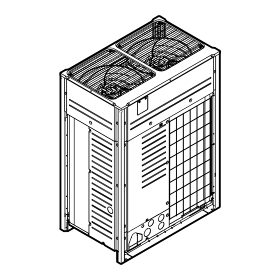
About the box a Packaging material b Belt sling c Opening d Protector NOTICE Use a belt sling of ≤20 mm wide that adequately bears the weight of the unit. ▪ A forklift can only be used for transport as long as the unit remains on its pallet as shown above. -
Page 53: To Remove The Accessories From The Outdoor Unit
About the box 15.4 To remove the accessories from the outdoor unit 8~12 HP 14~20 HP Make sure that all accessories are available in the unit. 1× 1× 1× 1× 1× REQUEST FOR THE INDICATION OF INSTALLATION INFORMATION REQUEST FOR THE INDICATION OF ADDITIONAL REFRIGERANT CHARGING AND LEAK DETECTION OPERATION RESULT BE SURE TO FILL OUT THE BLANKS, WHICH ARE NEEDED FOR AFTER-SALE SERVICES. -
Page 54: To Remove The Transportation Stay
About the box Accessory pipes (mm) Øa Øb Liquid pipe ▪ Front connection ID Øb 12.7 ID Øa 12.7 ▪ Bottom connection ID Øb 12.7 15.9 ID Øa Equaliser pipe 19.1 ▪ Front connection ID Øa 19.1 22.2 ID Øb ▪... -
Page 55: About The Units And Options
About the units and options 16 About the units and options In this chapter 16.1 Overview: About the units and options ..........................16.2 Identification label: Outdoor unit............................16.3 About the outdoor unit ................................16.4 System layout..................................16.5 Combining units and options..............................16.5.1 About combining units and options........................ -
Page 56: About The Outdoor Unit
About the units and options Code Explanation Model series Power supply European market Minor model change indication (a) For RXYQ, there is no restriction on use as multi module. 16.3 About the outdoor unit This installation manual concerns the VRV IV, full inverter driven, heat pump system. -
Page 57: Combining Units And Options
About the units and options a VRV IV Heat pump outdoor unit b Refrigerant piping c VRV direct expansion (DX) indoor unit d VRV LT Hydrobox (HXY080/125) e BP box (required to connect Residential Air (RA) or Sky Air (SA) direct expansion (DX) indoor units) f Residential Air (RA) direct expansion (DX) indoor units) g User interface (dedicated depending on indoor unit type) -
Page 58: Possible Combinations Of Outdoor Units
About the units and options ▪ Aircurtain (air to air applications): CYQ/CAV (Biddle) series, depending on application. 16.5.3 Possible combinations of outdoor units Possible standalone outdoor units Non-continuous heating Continuous heating RXYQ8 RYYQ8 RXYQ10 RYYQ10 RXYQ12 RYYQ12 RXYQ14 RYYQ14 RXYQ16 RYYQ16 RXYQ18 RYYQ18... -
Page 59: Possible Options For The Outdoor Unit
About the units and options Non-continuous heating Continuous heating RXYQ54 = RXYQ18 + 18 + 18 RYYQ54 = RYMQ18 + 18 + 18 16.5.4 Possible options for the outdoor unit INFORMATION Refer to the technical engineering data for the latest option names. Refrigerant branching kit Description Model name... - Page 60 About the units and options Heater tape kit To keep the drain holes free in cold climates with high humidity, you can install a heater tape kit. If you do so, you also have to install the heater tape PCB kit. Description Model name Heater tape kit for 8~12 HP...
-
Page 61: Unit Installation
Unit installation 17 Unit installation In this chapter 17.1 Preparing the installation site ..............................17.1.1 Installation site requirements of the outdoor unit ....................17.1.2 Additional installation site requirements of the outdoor unit in cold climates ........... 17.1.3 Securing safety against refrigerant leaks....................... 17.2 Opening the unit.................................. - Page 62 Unit installation (mm) a Personal computer or radio b Fuse c Earth leakage protector d User interface e Indoor unit f Outdoor unit ▪ In places with weak reception, keep distances of 3 m or more to avoid electromagnetic disturbance of other equipment and use conduit tubes for power and transmission lines.
-
Page 63: Additional Installation Site Requirements Of The Outdoor Unit In Cold Climates
Unit installation ▪ Height of windbreaker≥1.5×height of outdoor unit ▪ Mind the service space requirements when installing the windbreaker. a Sea wind b Building c Outdoor unit d Windbreaker ▪ All piping lengths and distances have been taken into consideration (see "About the piping length" [... -
Page 64: Securing Safety Against Refrigerant Leaks
Ambient outdoor temperature If the unit has to operate for 5 days in this area with high humidity (>90%), Daikin recommends to install the optional heater tape kit (EKBPH012TA or EKBPH020TA) to keep the drain holes free. 17.1.3 Securing safety against refrigerant leaks... - Page 65 Unit installation a Direction of the refrigerant flow b Room where refrigerant leak has occurred (outflow of all the refrigerant from the system) Pay special attention to places such as basements etc., where refrigerant can accumulate, since refrigerant is heavier than air. To check the maximum concentration level Check the maximum concentration level in accordance with steps 1 to 4 below and take whatever action is necessary to comply.
-
Page 66: Opening The Unit
Unit installation When there is a room division that has an opening sufficiently large to permit free air flow. a Opening between the rooms. In case there is a door the openings above and below the door each must be equivalent in size to 0.15% or more of the floor area. -
Page 67: To Open The Electrical Component Box Of The Outdoor Unit
Unit installation 8~12 HP 14~20 HP 14× 14× Once the front plates open, the electrical component box can be accessed. See "To open the electrical component box of the outdoor unit" [ 67]. For service purposes, the pushbuttons on the main PCB need to be accessed. To access these pushbuttons, the electrical component box cover does not need to be opened. -
Page 68: Mounting The Outdoor Unit
Unit installation d Sealing material e Moisture and dirt could enter NOT allowed Allowed 17.3 Mounting the outdoor unit 17.3.1 To provide the installation structure Make sure the unit is installed level on a sufficiently strong base to prevent vibration and noise. NOTICE ▪... - Page 69 Unit installation NOTICE ▪ Prepare a water drainage channel around the foundation to drain waste water from around the unit. During heating operation and when the outdoor temperatures are negative, the drained water from the outdoor unit will freeze up. If the water drainage is not taken care of, the area around the unit might be very slippery.
-
Page 70: Piping Installation
Piping installation 18 Piping installation In this chapter 18.1 Preparing refrigerant piping ..............................18.1.1 Refrigerant piping requirements ........................... 18.1.2 Refrigerant piping insulation..........................18.1.3 To select the piping size ............................18.1.4 To select refrigerant branch kits..........................18.1.5 About the piping length ............................18.1.6 Piping length: VRV DX only............................. -
Page 71: Refrigerant Piping Insulation
Piping installation NOTICE The piping and other pressure-containing parts shall be suitable for refrigerant. Use phosphoric acid deoxidised seamless copper for refrigerant. ▪ Only use phosphoric acid deoxidised seamless copper. ▪ Foreign materials inside pipes (including oils for fabrication) must be ≤30 mg/10 m. - Page 72 Piping installation Outdoor unit capacity Piping outer diameter size (mm) type (HP) Gas pipe Liquid pipe 19.1 22.2 12~16 28.6 12.7 18~22 28.6 15.9 34.9 15.9 26~34 34.9 19.1 36~54 41.3 19.1 D: Piping between refrigerant branch kits Choose from the following table in accordance with the indoor unit total capacity type, connected downstream.
- Page 73 Piping installation a Outdoor unit b Main pipes (increase if the equivalent piping length is ≥90 m) c First refrigerant branch kit d Piping between refrigerant branch kit and indoor unit e Indoor unit Size up HP class Piping outer diameter size (mm) Gas pipe Liquid pipe 19.1 →...
-
Page 74: To Select Refrigerant Branch Kits
Piping installation Total capacity index of Piping outer diameter size (mm) connected indoor units Gas pipe Liquid pipe 20~62 12.7 63~149 15.9 150~208 19.1 Example: Downstream capacity for F=[capacity index of unit 4]+[capacity index of unit 5] G: Piping between branch selector box (BP box) and RA DX indoor unit Only in case RA DX indoor units are connected. - Page 75 Piping installation Indoor unit capacity index 2 pipes ≥640 KHRQ22M75H (a) If the pipe size above the refnet header is Ø34.9 or more, KHRQ22M75H is required. INFORMATION Maximum 8 branches can be connected to a header. ▪ How to choose an outdoor multi connection piping kit. Choose from the following table in accordance with the number of outdoor units.
-
Page 76: About The Piping Length
Piping installation 18.1.5 About the piping length Make sure to perform the piping installation within the range of the maximum allowable pipe length, allowable level difference and allowable length after branching as indicated below. Three patterns will be discussed, including VRV DX indoor units combined with Hydrobox units or RA DX indoor units. - Page 77 Piping installation Example Description Example 1.3 Single outdoor Branch with refnet header Example 2.1 Multi outdoor Branch with refnet joint Example 2.2 Multi outdoor Branch with refnet joint and refnet header Example 2.3 Multi outdoor Branch with refnet header Example 3 With standard multi layout Indoor unit Refnet joint...
- Page 78 Piping installation Actual piping length 165 m/135 m Example 1.1 ▪ unit 8: a+b+c+d+e+f+g+p≤165 m Example 1.2 ▪ unit 6: a+b+h≤165 m ▪ unit 8: a+i+k≤165 m Example 1.3 ▪ unit 8: a+i≤165 m Example 2.1 ▪ unit 8: a+b+c+d+e+f+g+p≤135 m Equivalent length 190 m/160 m Total piping length 1000 m/500 m Example 1.1 ▪ a+b+c+d+e+f+g+h+i+j+k+l+m+n+p≤1000 m Example 2.1 ▪...
- Page 79 Piping installation ≤30 m ≤5 m Maximum allowable length after branch The pipe length from the first refrigerant branch kit to the indoor unit ≤40 m. Example 1.1: unit 8: b+c+d+e+f+g+p≤40 m Example 1.2: unit 6: b+h≤40 m, unit 8: i+k≤40 m Example 1.3: unit 8: i≤40 m However, extension is possible if all below conditions are met.
-
Page 80: Piping Length: Vrv Dx And Hydrobox
Piping installation 18.1.7 Piping length: VRV DX and Hydrobox For system containing VRV DX indoor units and Hydrobox: System setup Example Description Example 1 Branch with refnet joint Example 2 Branch with refnet joint and refnet header Example 3 Branch with refnet header 1~7 VRV DX indoor units 8 Hydrobox unit (HXY080/125) Maximum allowable length... -
Page 81: Piping Length: Vrv Dx And Ra Dx
Piping installation Maximum allowable length after branch The pipe length from the first refrigerant branch kit to the indoor unit ≤40 m. Example 1: unit 8: b+c+d+e+f+g+p≤40 m Example 2: unit 6: b+h≤40 m, unit 8: i+k≤40 m Example 3: unit 8: i≤40 m, unit 2: c≤40 m 18.1.8 Piping length: VRV DX and RA DX For system containing VRV DX indoor units and RA DX indoor units: System setup... -
Page 82: Multiple Outdoor Units: Possible Layouts
Piping installation Maximum allowable height difference ≤50 m (40 m) (if outdoor is located below indoor units) ≤15 m ≤40 m ≤15 m ≤5 m Maximum allowable length after branch The pipe length from the first refrigerant branch kit to the indoor unit ≤50 m. Example: b+g+l≤50 m If the piping length between the first branch and BP unit or VRV DX indoor unit is over 20 ... -
Page 83: Connecting The Refrigerant Piping
Piping installation a To indoor unit b Oil collects to the outmost outdoor unit when the system stops NOT allowed (oil remains in piping) Allowed ▪ If the piping length between the outdoor units exceeds 2 m, create a rise of 200 mm or more in the gas line within a length of 2 m from the kit. -
Page 84: Precautions When Connecting The Refrigerant Piping
Piping installation ▪ Protecting the outdoor unit against contamination ▪ Connecting the refrigerant piping to the indoor units (see the installation manual of the indoor units) ▪ Connecting the multi-connection piping kit ▪ Connecting the refrigerant branching kit ▪ Keeping in mind the guidelines for: Brazing Using the stop valves Removing the pinched pipes... -
Page 85: Multiple Outdoor Units: Knockout Holes
Piping installation 18.2.3 Multiple outdoor units: Knockout holes Connection Description Front connection Remove the front plate knockout holes to connect. Bottom connection Remove the knockout holes on the bottom frame and route the piping under the bottom. 18.2.4 To route the refrigerant piping Installation of refrigerant piping is possible as front connection or side connection (when taken out from the bottom) as shown in the figure below. -
Page 86: To Connect The Refrigerant Piping To The Outdoor Unit
Piping installation NOTICE Precautions when making knockout holes: ▪ Avoid damaging the casing. ▪ After making the knockout holes, we recommend you remove the burrs and paint the edges and areas around the edges using repair paint to prevent rusting. ▪... -
Page 87: To Connect The Refrigerant Branching Kit
Piping installation 7.5° 7.5° a Caution label NOT allowed Allowed ▪ Make sure that the total length of the piping connected to the joint is absolute straight for more than 500 mm. Only if a straight field piping of more than 120 mm is connected, more than 500 mm of straight section can be ensured. -
Page 88: To Braze The Pipe End
Piping installation Seal the piping and wiring intake holes using sealing material (field supply), otherwise the capacity of the unit will drop and small animals may enter the machine. Example: passing piping out through the front. a Close the areas marked with " ". -
Page 89: Using The Stop Valve And Service Port
Piping installation ▪ Do NOT use flux when brazing copper-to-copper refrigerant piping. Use phosphor copper brazing filler alloy (BCuP), which does not require flux. Flux has an extremely harmful influence on refrigerant piping systems. For instance, if chlorine based flux is used, it will cause pipe corrosion or, in particular, if the flux contains fluorine, it will deteriorate the refrigerant oil. - Page 90 Piping installation 3 When the stop valve cannot be turned any further, stop turning. 4 Install the stop valve cover. Result: The valve is now open. To fully open the Ø19.1~Ø25.4 mm stop valve, turn the hexagonal wrench until a torque between 27 and 33 N•m is achieved. Inadequate torque may cause leakage of refrigerant and breakage of the stop valve cap.
-
Page 91: To Remove The Spun Pipes
Piping installation To handle the service port ▪ Always use a charge hose equipped with a valve depressor pin, since the service port is a Schrader type valve. ▪ After handling the service port, make sure to tighten the service port cover securely. -
Page 92: Checking The Refrigerant Piping
Piping installation 4 When all gas and oil is recovered from the spun piping, disconnect the charge hose and close the service ports. 5 Cut off the lower part of the gas, liquid and equalising stop valve pipes along the black line. Use an appropriate tool (e.g. a pipe cutter). WARNING NEVER remove the spun piping by brazing. -
Page 93: Checking Refrigerant Piping: General Guidelines
Piping installation Method 1: Before power ON If the system has not yet been powered on, no special action is required to perform the leak test and the vacuum drying. Method 2: After power ON If the system has already been powered on, activate setting [2‑21] (refer to "To access mode 1 or 2" ... -
Page 94: Checking Refrigerant Piping: Setup
Piping installation NOTICE Make sure the pump oil does not flow oppositely into the system while the pump is not working. NOTICE Do NOT purge the air with refrigerants. Use a vacuum pump to evacuate the installation. 18.3.3 Checking refrigerant piping: Setup p <... -
Page 95: To Perform Vacuum Drying
Piping installation 2 Once reached, turn off the vacuum pump and check that the pressure does not rise for at least 1 minute. 3 Should the pressure rise, the system may either contain moisture (see vacuum drying below) or have leaks. To check for leaks: Pressure leak test 1 Test for leaks by applying a bubble test solution to all piping connections. -
Page 96: To Insulate The Refrigerant Piping
Piping installation 18.3.6 To insulate the refrigerant piping After finishing the leak test and vacuum drying, the piping must be insulated. Take into account the following points: ▪ Make sure to insulate the connection piping and refrigerant branch kits entirely. ▪... -
Page 97: About Charging Refrigerant
Piping installation NOTICE Be sure to turn ON the power 6 hours before operation in order to have power running to the crankcase heater and to protect the compressor. NOTICE If operation is performed within 12 minutes after the indoor and outdoor units are powered on, the compressor will not operate before the communication is established in a correct way between outdoor unit(s) and indoor units. -
Page 98: To Determine The Additional Refrigerant Amount
Piping installation A flow chart is available which gives an overview of the possibilities and actions to be taken (see "To charge refrigerant: Flow chart" [ 101]). 18.4.3 To determine the additional refrigerant amount INFORMATION For final charge adjustment in the test laboratory, please contact your local dealer. NOTICE The refrigerant charge of the system must be less than 100 ... - Page 99 Piping installation Parameter C Model CR≥100% CR<100% Then Then 8 HP N≥4 C=N×0.1 kg N<4 C=0 kg C=0 kg 10 HP N≥5 N<5 12 HP N≥6 N<6 14 HP N≥7 N<7 16 HP N≥8 N<8 18 HP N≥9 N<9 20 HP N≥10 N<10 (a) In case of a multi-outdoor-unit system, add the sum of the individual outdoor unit charge factors.
- Page 100 Piping installation Connection ratio requirements. When selecting indoor units, the connection ratio must comply with the following requirements. For more information, see the technical engineering data. Other combinations than those mentioned in the table are not allowed. Indoor units Total CR CR per type VRV DX RA DX...
-
Page 101: To Charge Refrigerant: Flow Chart
Piping installation 18.4.4 To charge refrigerant: Flow chart For more information, see "To charge refrigerant" [ 103]. Pre-charging refrigerant Step 1 p < p > Calculate additional refrigerant charge amount: R (kg) Step 2+3 R410A • Open valves C, D and B to the liquid and equalising line •... - Page 102 Piping installation Charging refrigerant << Continuation of previous page R>Q Step 5 p < p > • Connect valve A to the refrigerant charge port (d) • Open all outdoor unit stop valves R410A Step 6 Proceed with automatic or manual charge Automatic charge Manual charge Step 6a...
-
Page 103: To Charge Refrigerant
Piping installation << Continuation of previous page Heating charging Cooling charging ("t22" startup control) ("t02" startup control) ("t23" waiting for stable heating) ("t03" waiting for stable cooling) "t23" is flashing "t03" is flashing • Push BS2 within 5 minutes • Push BS2 within 5 minutes •... - Page 104 Piping installation Then The additional refrigerant amount is Perform steps 3~4. smaller than 10 kg The additional refrigerant charge is Perform steps 3~6. larger than 10 kg 3 Pre-charging can be done without compressor operation, by connecting the refrigerant bottle to the service ports of the liquid and equalising stop valves (open valve B).
- Page 105 Piping installation Charging refrigerant 5 After pre-charging, connect valve A to the refrigerant charge port and charge the remaining additional refrigerant through this port. Open all outdoor unit stop valves. At this point, valve A must remain closed! p < p >...
-
Page 106: Step 6A: To Automatically Charge Refrigerant
Piping installation 18.4.6 Step 6a: To automatically charge refrigerant INFORMATION The automatic refrigerant charging has limits as described below. Out of these limits, the system cannot operate the automatic refrigerant charging: ▪ Outdoor temperature: 0~43°C DB. ▪ Indoor temperature: 10~32°C DB. ▪ Total indoor unit capacity: ≥80%. -
Page 107: Step 6B: To Manually Charge Refrigerant
Piping installation Then " ", " ", or " " appears Push BS1 to finish the automatic charging function procedure. The ambient conditions are favourable to execute the test run. " ", or " " appears The ambient conditions are NOT favourable to execute the test run. -
Page 108: Error Codes When Charging Refrigerant
Piping installation 3 Activate outdoor unit setting [2‑20]=1 to start manual refrigerant charge mode. Refer to "Mode 2: Field settings" [ 130] for details. Result: The unit will start operation. 4 Valve A can be opened. Charging of remaining additional refrigerant can be done. -
Page 109: Checks After Charging Refrigerant
Piping installation Code Cause Solution Indicates an indoor unit which Refer to requirements to be is not compatible with leak able to execute leak detection detection functionality is operation. installed (e.g., RA DX indoor unit, Hydrobox, …) Other — Close valve A immediately. malfunction Confirm the malfunction code code... -
Page 110: Electrical Installation
Electrical installation 19 Electrical installation In this chapter 19.1 About connecting the electrical wiring ..........................110 19.1.1 Precautions when connecting the electrical wiring ....................110 19.1.2 Field wiring: Overview............................112 19.1.3 About the electrical wiring............................. 112 19.1.4 Guidelines when knocking out knockout holes ..................... 113 19.1.5 About electrical compliance .......................... - Page 111 Electrical installation WARNING ▪ If the power supply has a missing or wrong N-phase, equipment might break down. ▪ Establish proper earthing. Do NOT earth the unit to a utility pipe, surge absorber, or telephone earth. Incomplete earthing may cause electrical shock. ▪...
-
Page 112: Field Wiring: Overview
Electrical installation NOTICE Only applicable if the power supply is three‑phase, and the compressor has an ON/ OFF starting method. If there exists the possibility of reversed phase after a momentary black out and the power goes on and off while the product is operating, attach a reversed phase protection circuit locally. -
Page 113: Guidelines When Knocking Out Knockout Holes
Electrical installation Field piping can be routed from front or bottom of the unit (going left or right). Refer to "To route the refrigerant piping" [ 85]. ▪ Be sure to follow the limits below. If the unit-to-unit cables are beyond these limits, it may result in malfunction of transmission: Maximum wiring length: 1000 m. -
Page 114: About Electrical Compliance
Electrical installation a Knockout hole b Burr c Remove burrs d If there are any possibilities that small animals enter the system through the knockout holes, close the holes with packing materials (to be prepared on-site) 19.1.5 About electrical compliance This equipment complies with: ▪... -
Page 115: Safety Device Requirements
Electrical installation Model (Ω) Minimum S value (kVA) RYYQ32/RXYQ32 — 15094 RYYQ34/RXYQ34 — 16352 RYYQ36/RXYQ36 — 17359 RYYQ38/RXYQ38 — 19397 RYYQ40/RXYQ40 — 20378 RYYQ42/RXYQ42 — 20629 RYYQ44/RXYQ44 — 21132 RYYQ46/RXYQ46 — 21887 RYYQ48/RXYQ48 — 22641 RYYQ50/RXYQ50 — 23899 RYYQ52/RXYQ52 — 25157 RYYQ54/RXYQ54 —... - Page 116 Electrical installation Model Minimum circuit Recommended ampacity fuses RYYQ28/RXYQ28 55.0 A 63 A RYYQ30/RXYQ30 59.0 A 80 A RYYQ32/RXYQ32 62.0 A 80 A RYYQ34/RXYQ34 66.0 A 80 A RYYQ36/RXYQ36 70.0 A 80 A RYYQ38/RXYQ38 76.0 A 100 A RYYQ40/RXYQ40 81.0 A 100 A RYYQ42/RXYQ42 84.0 A 100 A RYYQ44/RXYQ44 86.0 A 100 A RYYQ46/RXYQ46 89.0 A 100 A RYYQ48/RXYQ48 93.0 A 125 A RYYQ50/RXYQ50 97.0 A...
-
Page 117: To Route And Fix The Transmission Wiring
Electrical installation 19.2 To route and fix the transmission wiring Transmission wiring can be routed through the front side only. Fix it to the upper mounting hole. 8~12 HP 14~20 HP a Transmission wiring (possibility 1) b Transmission wiring (possibility 2) . -
Page 118: To Connect The Transmission Wiring
Electrical installation 19.3 To connect the transmission wiring The wiring from the indoor units must be connected to the F1/F2 (In‑Out) terminals on the PCB in the outdoor unit. Tightening torque for the transmission wiring terminal screws: Screw size Tightening torque (N•m) M3.5 (A1P) 0.8~0.96 In case of single outdoor unit installation... -
Page 119: To Finish The Transmission Wiring
Electrical installation 19.4 To finish the transmission wiring After installing the transmission wires inside the unit, wrap them along with the on- site refrigerant pipes using finishing tape, as shown in figure below. a Liquid pipe b Gas pipe c Insulator d Transmission wiring (F1/F2) e Finishing tape 19.5 To route and fix the power supply... -
Page 120: To Connect The Power Supply
Electrical installation 19.6 To connect the power supply NOTICE Never connect the power supply to transmission wiring terminal block. Otherwise the entire system may break down. INFORMATION Installation and routing in case the cool/heat selector is used: refer to the installation manual of the cool/heat selector. -
Page 121: To Check The Insulation Resistance Of The Compressor
Electrical installation e Power supply terminal block f Connect each power wire: RED to L1, WHT to L2, BLK to L3 and BLU to N g Earth wire (GRN/YLW) h Tie wrap i Cup washer j When connecting the earth wire, it is recommended to perform curling. Multiple outdoor units To connect the power supply for multiple outdoor units to each other, ring tongues have to be used. -
Page 122: Configuration
Configuration 20 Configuration In this chapter 20.1 Overview: Configuration................................. 122 20.2 Making field settings................................122 20.2.1 About making field settings ........................... 122 20.2.2 Field setting components............................124 20.2.3 To access the field setting components ........................ 124 20.2.4 To access mode 1 or 2............................125 20.2.5 To use mode 1................................ - Page 123 Configuration Push buttons and DIP switches Item Description Push buttons By operating the push buttons it is possible to: ▪ Perform special actions (automatic refrigerant charge, testrun, etc). ▪ Perform field settings (demand operation, low noise, etc). DIP switches By operating the DIP switches it is possible to: ▪...
-
Page 124: Field Setting Components
Configuration ▪ "Mode 2: Field settings" [ 130] 20.2.2 Field setting components Location of the 7‑segment displays, buttons and DIP switches: DS1 DS2 BS1 BS2 X27A BS1 MODE: For changing the set mode BS2 SET: For field setting BS3 RETURN: For field setting DS1, DS2 DIP switches a 7‑segment displays b Push buttons... -
Page 125: To Access Mode 1 Or 2
Configuration 20.2.4 To access mode 1 or 2 Initialisation: default situation NOTICE Be sure to turn ON the power 6 hours before operation in order to have power running to the crankcase heater and to protect the compressor. Turn on the power supply of the outdoor unit and all indoor units. When the communication between indoor units and outdoor unit(s) is established and normal, the 7‑segment display indication state will be as below (default situation when shipped from factory). -
Page 126: To Use Mode 1
Configuration 20.2.5 To use mode 1 Mode 1 is used to set basic settings and to monitor the status of the unit. What Changing and accessing the Once mode 1 is selected (push BS1 one time), setting in mode 1 you can select the wanted setting. It is done by pushing BS2. -
Page 127: Mode 1: Monitoring Settings
Configuration What Changing the value of the ▪ Once mode 2 is selected (push BS1 for more selected setting in mode 2 than 5 seconds) you can select the wanted setting. It is done by pushing BS2. ▪ Accessing the selected setting's value is done by pushing BS3 1 time. - Page 128 Configuration [1‑0] Description Outdoor unit is slave 1 unit. Outdoor unit is slave 2 unit. [1‑1] Shows the status of low noise operation. Low noise operation reduces the sound generated by the unit compared to nominal operating conditions. [1‑1] Description Unit is currently not operating under low noise restrictions.
- Page 129 Configuration It can be convenient to check if the total number of indoor units which are installed match the total number of indoor units which are recognised by the system. In case there is a mismatch, it is recommended to check the communication wiring path between outdoor and indoor units (F1/F2 communication line).
-
Page 130: Mode 2: Field Settings
Configuration When the automatic leak detection was activated through mode 2 settings, it is possible to see what was the last result of the automatic leak detection operation. [1‑35] [1‑36] [1‑37] Description Normal execution of leak detection operation occurred. Operation conditions during leak detection operation were not satisfied (ambient temperature was not within the limitations). - Page 131 Configuration It is necessary to use the optional external control adaptor for outdoor unit (DTA104A61/62). See the instruction delivered with the adaptor for further details. [2‑8] target temperature during cooling operation. [2‑8] target (°C) 0 (default) Auto For more information and advice about the impact of these settings, see "20.3 Energy saving and optimum operation" [ 137].
- Page 132 Configuration [2‑14] Additional amount charged (kg) 5<x<10 10<x<15 15<x<20 20<x<25 25<x<30 30<x<35 35<x<40 40<x<45 45<x<50 50<x<55 55<x<60 60<x<65 65<x<70 70<x<75 75<x<80 80<x<85 85<x<90 Setting cannot be used. Total refrigerant charge has to be <100 kg. ▪ For details concerning the charging procedure, see "About charging refrigerant" [ 97].
- Page 133 Configuration [2‑20] Description 0 (default) Deactivated. Activated. To stop the manual additional refrigerant charge operation (when the required additional refrigerant amount is charged), push BS3. If this function was not aborted by pushing BS3, the unit will stop its operation after 30 minutes.
- Page 134 Configuration [2‑26] Low noise operation start time. This setting is used in conjunction with setting [2‑22]. [2‑26] Start time automatic low noise operation (approximately) 20h00 2 (default) 22h00 24h00 [2‑27] Low noise operation stop time. This setting is used in conjunction with setting [2‑22]. [2‑27] Stop time automatic low noise operation (approximately)
- Page 135 Configuration [2‑31] Power consumption limitation (approximately) [2‑32] Forced, all time, power consumption limitation operation (no external control adaptor is required to perform power consumption limitation). If the system always needs to be running under power consumption limitation conditions, this setting activates and defines the level power consumption limitation that will be applied continuously.
- Page 136 Configuration [2‑81] Cooling comfort setting Powerful For more information and advice about the impact of these settings, see "20.3 Energy saving and optimum operation" [ 137]. [2‑82] Heating comfort setting. This setting is used in conjunction with setting [2‑9]. [2‑82] Heating comfort setting 1 (default) Mild Quick...
-
Page 137: To Connect The Pc Configurator To The Outdoor Unit
Configuration When you want to use the automatic leak detection function you have to activate this setting. By activating setting [2‑86], the automatic leak detection will be executed depending on the defined value setting. The timing for the next automatic refrigerant leak detection is subject to setting [2‑85]. The automatic leak detection will be executed in [2‑85] days. -
Page 138: Available Main Operation Methods
Configuration No matter which control is selected, variations on the behaviour of the system are still possible due to protection controls to keep the unit operating under reliable conditions. The intentional target, however, is fixed and will be used to obtain the best balance between energy consumption and comfort, depending on the application type. -
Page 139: Available Comfort Settings
Configuration To activate this in… Change… Cooling operation [2‑8] to the appropriate value, matching the requirements of the pre-designed system containing a high sensible solution. Heating operation [2‑9] to the appropriate value, matching the requirements of the pre-designed system containing a high sensible solution. - Page 140 Configuration Quick Overshoot (during heating operation) or undershoot (during cooling operation) is allowed compared to the requested refrigerant temperature, in order to achieve the required room temperature very fast. The overshoot is allowed from the start up moment. ▪ In case of cooling operation the evaporating temperature is allowed to go down to 6°C on temporary base depending on the situation.
-
Page 141: Example: Automatic Mode During Cooling
Configuration To activate this in… Change… Cooling operation [2‑81]=0. This setting is used in conjunction with setting [2‑8]. Heating operation [2‑82]=0. This setting is used in conjunction with setting [2‑9]. 20.3.3 Example: Automatic mode during cooling 100% 6°C 3°C 35°C A Actual load curve B Virtual load curve (initial capacity automatic mode) C Virtual target value (initial evaporation temperature value automatic mode) -
Page 142: Example: Automatic Mode During Heating
Configuration Room temperature evolution: A Indoor unit set temperature B Operation start C Operating time D Mild E Quick F Powerful 20.3.4 Example: Automatic mode during heating 100% 49°C 46°C 2°C A Virtual load curve (default automatic mode peak capacity) B Load curve C Virtual target value (initial condensation temperature value automatic mode) D Design temperature... -
Page 143: Using The Leak Detection Function
Configuration Quick Powerful Mild Room temperature evolution: A Indoor unit set temperature B Operation start C Operating time D Mild E Quick F Powerful 20.4 Using the leak detection function 20.4.1 About automatic leak detection The (automatic) leak detection function is not by default activated. The (automatic) leak detection function can only start working when both below conditions are fulfilled: ▪... -
Page 144: To Manually Perform A Leak Detection
Configuration INFORMATION ▪ The weighed and already recorded amount of additional refrigerant charge (not the total amount of refrigerant present in the system) must be entered. ▪ The leak detection function is not available when Hydrobox units or RA DX indoor units are connected to the system. - Page 145 Configuration Display Leaked amount (kg) 8.5≤x<9 9≤x<9.5 9.5≤x<10 10≤x Information codes: Code Description Unit is not prepared to execute leak detection operation (refer to requirements to be able to execute leak detection operation). Indoor unit is out of temperature range for leak detection operation.
-
Page 146: Commissioning
21 Commissioning NOTICE General commissioning checklist. Next to the commissioning instructions in this chapter, a general commissioning checklist is also available on the Daikin Business Portal (authentication required). The general commissioning checklist is complementary to the instructions in this chapter and can be used as a guideline and reporting template during the commissioning and hand-over to the user. -
Page 147: Checklist Before Commissioning
Commissioning CAUTION Do NOT insert fingers, rods or other objects into the air inlet or outlet. Do NOT remove the fan guard. When the fan is rotating at high speed, it will cause injury. NOTICE Test run is possible for ambient temperatures between – 2 0°C and 35°C. INFORMATION During the first running period of the unit, the required power may be higher than stated on the nameplate of the unit. -
Page 148: About The Test Run
Commissioning Internal wiring Visually check the electrical component box and the inside of the unit for loose connections or damaged electrical components. Pipe size and pipe insulation Be sure that correct pipe sizes are installed and that the insulation work is properly executed. -
Page 149: To Perform A Test Run
Commissioning INFORMATION The refrigerant situation check cannot be performed beyond the following limits: ▪ Outdoor temperature: 0~43°C DB ▪ Indoor temperature: 20~32°C DB Value [2‑88] Description The test run will be executed including the detailed refrigerant situation check. After the test run, the unit will be prepared for leak detection functionality (for more details, see "20.4 Using the leak detection... -
Page 150: Correcting After Abnormal Completion Of The Test Run
Commissioning 2 Make sure all field settings you want are set; see "20.2 Making field settings" [ 122]. 3 Turn ON the power to the outdoor unit and the connected indoor units. NOTICE Be sure to turn ON the power 6 hours before operation in order to have power running to the crankcase heater and to protect the compressor. -
Page 151: Operating The Unit
Commissioning INFORMATION Refer to the installation manual of the indoor unit for detailed malfunction codes related to indoor units. 21.7 Operating the unit Once the unit is installed and test operation of outdoor unit and indoor units is finished, the operation of the system can start. For operating the indoor unit, the user interface of the indoor unit should be switched ON. -
Page 152: Hand-Over To The User
Hand-over to the user 22 Hand-over to the user Once the test run is finished and the unit operates properly, please make sure the following is clear for the user: ▪ Make sure that the user has the printed documentation and ask him/her to keep it for future reference. -
Page 153: Maintenance And Service
Maintenance and service 23 Maintenance and service NOTICE Maintenance MUST be done by an authorized installer or service agent. We recommend performing maintenance at least once a year. However, applicable legislation might require shorter maintenance intervals. NOTICE Applicable legislation on fluorinated greenhouse gases requires that the refrigerant charge of the unit is indicated both in weight and CO equivalent. -
Page 154: About Service Mode Operation
Maintenance and service 8~12 HP 14~20 HP X6A (A6P) X5A (A3P) 3 To prevent damaging the PCB, touch a non-coated metal part to eliminate static electricity before pulling out or plugging in connectors. 4 Pull out junction connectors X1A, X2A for the fan motors in the outdoor unit before starting service operation on the inverter equipment. - Page 155 Maintenance and service DANGER: RISK OF EXPLOSION Pump down – Refrigerant leakage. If you want to pump down the system, and there is a leak in the refrigerant circuit: ▪ Do NOT use the unit's automatic pump down function, with which you can collect all refrigerant from the system into the outdoor unit.
-
Page 156: Troubleshooting
Troubleshooting 24 Troubleshooting In this chapter 24.1 Solving problems based on error codes..........................156 24.2 Error codes: Overview ................................156 24.1 Solving problems based on error codes In case of a displayed malfunction code, perform correcting actions as explained in the malfunction code table. - Page 157 Troubleshooting Main code Sub code Cause Solution Master Slave 1 Slave 2 High pressure switch was Check stop valve situation or activated (S1PH, S2PH) - A1P abnormalities in (field) piping (X2A , X3A) or airflow over air cooled coil. ▪ Refrigerant overcharge ▪...
- Page 158 Troubleshooting Main code Sub code Cause Solution Master Slave 1 Slave 2 Discharge temperature sensor Check connection on PCB or malfunction (R21T): open actuator. circuit - A1P (X19A) Discharge temperature sensor Check connection on PCB or malfunction (R21T): short actuator. circuit - A1P (X19A) Discharge temperature sensor Check connection on PCB or...
- Page 159 Troubleshooting Main code Sub code Cause Solution Master Slave 1 Slave 2 High pressure sensor Check connection on PCB or malfunction (S1NPH): open actuator. circuit - A1P (X32A) High pressure sensor Check connection on PCB or malfunction (S1NPH): short actuator. circuit - A1P (X32A) Low pressure sensor Check connection on PCB or...
- Page 160 Troubleshooting Main code Sub code Cause Solution Master Slave 1 Slave 2 Warning indication: Leak Execute autocharge function detection or refrigerant (see manual); unit not ready amount check not performed for leak detection (system operation possible) functionality. Malfunction code: System test Execute system test run.
- Page 161 Troubleshooting Main code Sub code Cause Solution Master Slave 1 Slave 2 Auto address malfunction Check if transmission wired (inconsistency) unit amount matches with powered unit amount (by monitor mode) or wait till initialisation is finished. Stop valve closed or wrong Open stop valves.
-
Page 162: Disposal
Disposal 25 Disposal NOTICE Do NOT try to dismantle the system yourself: dismantling of the system, treatment of the refrigerant, oil and other parts MUST comply with applicable legislation. Units MUST be treated at a specialised treatment facility for reuse, recycling and recovery. RYYQ+RYMQ+RXYQ8~20U7Y1B Installer and user reference guide VRV IV+ heat pump... -
Page 163: Technical Data
Technical data 26 Technical data ▪ A subset of the latest technical data is available on the regional Daikin website (publicly accessible). ▪ The full set of latest technical data is available on the Daikin Business Portal (authentication required). In this chapter 26.1... - Page 164 Technical data Layout A+B+C+D Possibility 1 Possibility 2 a≥10 mm a≥50 mm — b≥300 mm b≥100 mm c≥10 mm c≥50 mm d≥500 mm d≥500 mm e≥20 mm e≥100 mm f≥600 mm f≥500 mm a≥10 mm a≥50 mm b≥300 mm b≥100 mm c≥10 mm c≥50 mm d≥500 mm d≥500 mm e≥20 mm e≥100 mm a≥10 mm a≥50 mm — b≥500 mm b≥500 mm c≥10 mm c≥50 mm d≥500 mm d≥500 mm e≥20 mm e≥100 mm...
-
Page 165: Piping Diagram: Outdoor Unit
Technical data 26.2 Piping diagram: Outdoor unit Piping diagram: RYYQ8~12 (S1NPL) (S1NPH) (S1PH) R21T a Compressor (M1C) b Compressor (M2C) c Heat exchanger d Fan e Fan motor (M1F, M2F) f Accumulator g Expansion valve, main (Y1E) h Expansion valve, subcool heat exchanger (Y2E) i Expansion valve, storage vessel (Y4E) j Subcool heat exchanger k Oil separator... - Page 166 Technical data Piping diagram: RYYQ14~20 (S1NPL) (S1NPH) (S1PH) (S2PH) R22T R21T a Compressor (M1C) b Compressor (M2C) c Heat exchanger d Fan e Fan motor (M1F, M2F) f Accumulator g Expansion valve, main (Y1E) h Expansion valve, subcool heat exchanger (Y2E) i Expansion valve, storage vessel (Y4E) j Subcool heat exchanger k Oil separator...
- Page 167 Technical data Piping diagram: RYMQ8~12 (S1NPL) (S1NPH) (S1PH) R21T a Compressor (M1C) b Compressor (M2C) c Heat exchanger d Fan e Fan motor (M1F, M2F) f Accumulator g Expansion valve, main (Y1E) h Expansion valve, subcool heat exchanger (Y2E) i Expansion valve, storage vessel (Y4E) j Subcool heat exchanger k Oil separator l Solenoid valve, oil accumulator (Y2S)
- Page 168 Technical data a Compressor (M1C) b Compressor (M2C) c Heat exchanger d Fan e Fan motor (M1F, M2F) f Accumulator g Expansion valve, main (Y1E) h Expansion valve, subcool heat exchanger (Y2E) i Expansion valve, storage vessel (Y4E) j Subcool heat exchanger k Oil separator l Solenoid valve, oil accumulator (Y2S) m Solenoid valve, oil1 (Y3S)
-
Page 169: Wiring Diagram: Outdoor Unit
Technical data Piping diagram: RXYQ14~20 (S1NPL) (S1NPH) (S1PH) (S2PH) R22T R21T a Compressor (M1C) b Compressor (M2C) c Heat exchanger d Fan e Fan motor (M1F, M2F) f Accumulator g Expansion valve, main (Y1E) h Expansion valve, subcool heat exchanger (Y2E) i Expansion valve, storage vessel (Y4E) j Subcool heat exchanger k Oil separator... - Page 170 Technical data For connection wiring to indoor–outdoor transmission F1‑F2, outdoor‑outdoor transmission F1‑F2, outdoor‑multi transmission Q1‑Q2, refer to the installation manual. How to use BS1~BS3 switch, refer to the "Service Precaution" label on the electrical component box cover. When operating, do NOT short-circuit the protection devices (S1PH). Only for RYYQ model Only for RYYQ/RYMQ model For 8~12 HP: Connector X1A (M1F) is white, connector X2A (M2F) is red.
- Page 171 Technical data E1HC Crankcase heater Drain pan heater (option) F1U, F2U (A1P) Fuse (T 3.15 A / 250 V) Field fuse F101U (A4P) Fuse F401U, F403U Fuse (A2P) F601U, (A3P) Fuse HAP (A*P) Pilot lamp (service monitor is green) K3R (A3P) Magnetic relay K4R (A1P) Magnetic relay (Y1S) K5R (A1P)
- Page 172 Technical data V1D (A3P) Diode V1R (A3P, A4P) Power module Connector X1M (A1P) Terminal block (control) X1M (A5P) Terminal block (power supply)(option) Electronic expansion valve (main) Electronic expansion valve (sub‑cool) Electronic expansion valve (liquid cooling) Electronic expansion valve (storage vessel) Solenoid valve (main) Solenoid valve (accumulator oil return) Solenoid valve (oil 1)
- Page 173 Technical data F601U, (A3P, Fuse A6P) HAP (A*P) Pilot lamp (service monitor is green) K3R (A3P, A6P) Magnetic relay K3R (A1P) Magnetic relay (Y4S) K4R (A1P) Magnetic relay (Y1S) K5R (A1P) Magnetic relay (Y2S) K6R (A1P) Magnetic relay (E3H) K7R (A1P) Magnetic relay (E1HC) K8R (A1P) Magnetic relay (E2HC)
- Page 174 Technical data Connector X1M (A1P) Terminal block (control) X1M (A8P) Terminal block (power supply)(option) Electronic expansion valve (main) Electronic expansion valve (sub‑cool) Electronic expansion valve (liquid cooling) Electronic expansion valve (storage vessel) Solenoid valve (main) Solenoid valve (accumulator oil return) Solenoid valve (oil 1) Solenoid valve (oil 2) Solenoid valve (subcool)
-
Page 175: Glossary
Optional equipment Equipment made or approved by Daikin that can be combined with the product according to the instructions in the accompanying documentation. Field supply Equipment NOT made by Daikin that can be combined with the product according to the instructions in the accompanying documentation. - Page 176 4P546228-1B 2020.10 Verantwortung für Energie und Umwelt...
Need help?
Do you have a question about the VRV IV+ RYYQ14U7Y1B Series and is the answer not in the manual?
Questions and answers