Advertisement
Quick Links
Evaluating the AD8460 High Power, High Speed Arbitrary Waveform Driver
Features
•
Enables easy evaluation of the AD8460
• Easy connection to any controller board
• Robust thermal management
Applications
• Automatic test equipment (ATE)
• Display panel formation and testing
• Piezo drivers
• Programmable power supplies
Evaluation Kit Contents
• EVAL-AD8460SDZ evaluation board
• Aluminum heat sink
• Tubeaxial fan
Hardware and Software Required
• SDP-H1 or SDP-B controller board, must be
purchased separately
• ACE software
• EVAL-AD8460SDZ ACE plugin
General Description
This user guide describes the EVAL-AD8460SDZ board,
which evaluates the AD8460 offered in a 12 mm × 12 mm,
80-lead thin quad flat package (TQFP) with an exposed
pad at the top for a mountable heat sink. The evaluation
board provides a platform for quick and easy evaluation of
the AD8460 for various user-defined configurations.
The AD8460 is ideally suited for demanding applications
such as high-speed arbitrary waveform generation,
programmable power supplies, and LCD/OLED panel
formation.
The evaluation board hardware and software enable full
operation of the AD8460 analog pattern generation (APG)
and arbitrary waveform generation (AWG) modes. The
AD8460 data sheet provides the full specifications of the
AD8460 and details on the device operation. Consult it in
conjunction with the user guide.
Rev.0
O n e A n a l o g Wa y , W i lm i ng t o n, M A 0 1 8 8 7 - 2 3 5 6 , U . S . A .
Evaluation Board User Guide
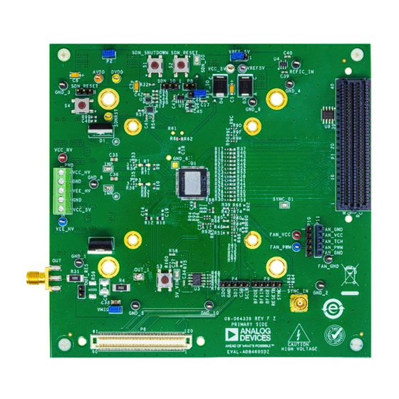
Evaluation Board Photographs
Figure 1. Front of AD8460 Evaluation Board
Warning: This high voltage evaluation board contains
exposed metal carrying lethal voltages when under power.
Take all necessary steps to protect users during operation.
For full precautions when using this high voltage
evaluation board, see the
section.
DOCUMENT FEEDBACK
T e l : 7 8 1 . 3 2 9 . 4 7 0 0
© 2 0 2 3 A n a l o g D e v i c e s , In c . A l l r i g h t s r e s e r v e d .
AD8460
High Voltage Evaluation Board
TECHNICAL SUPPORT
Advertisement

Related Manuals for Analog Devices EVAL-AD8460SDZ


Summary of Contents for Analog Devices EVAL-AD8460SDZ
- Page 1 Warning: This high voltage evaluation board contains General Description exposed metal carrying lethal voltages when under power. This user guide describes the EVAL-AD8460SDZ board, Take all necessary steps to protect users during operation. which evaluates the AD8460 offered in a 12 mm × 12 mm,...
-
Page 2: Initial Setup
AD8460 Evaluation Board User Guide Initial Setup The complete AD8460 evaluation system includes the AD8460 evaluation board, SDP board, and the AD8460 ACE plug- in. Plug-ins are product-specific applications downloaded and run in the analysis/control/evaluation (ACE) software environment. The AD8460 evaluation board communicates with Microsoft Windows 10 and ACE software through the SDP board. - Page 3 AD8460 Evaluation Board User Guide Evaluation Board Software Installation 1. Download the ACE installer software from www.analog.com/ace. 2. Install the ACE application and any other recommendations like SDP drivers. Note: This might require a system reboot at the end. So, save any open files and close any other running applications beforehand.
- Page 4 AD8460 Evaluation Board User Guide Figure 5. AD8460 Evaluation Board Factory Default Jumper Position Spread a thin layer of low-impedance thermal compound about 1 ml thick on top of the AD8460. Apply Kapton tape to the edges of the heatsink, as seen in Figure 6, to not touch the AD8460.
- Page 5 AD8460 Evaluation Board User Guide Mount the heat sink and secure four screws (PN 9902) onto the board with four hex nuts (PN HNSS440), as shown in Figure 7. Use a torque screwdriver to alternatively tighten the four screws, alternating diagonally like tightening lug nuts on a car tire, to 6 in-oz on each.
- Page 6 AD8460 Evaluation Board User Guide Use four screws (PN 010440CD125) to secure the fan onto the standoffs. Then, attach the black wire of the fan to FAN_GND and attach the red wire of the fan to FAN_VCC of the female connector P11. See Figure FAN CONNECTION Figure 9.
- Page 7 AD8460 Evaluation Board User Guide A load capacitor can be installed on the board at C8, or an off-board load may be connected through the OUT_RES test point. Use caution when driving a load that the AD8460 does not exceed its maximum allowable temperature of 150°C. Connect the high voltage supply through VEE_HV, VCC_HV, and GND test points.
- Page 8 AD8460 Evaluation Board User Guide Figure 12. AD8460 and SDP Board Connected to P7 on the Top Connect and plug in the SDP-H1 board power adapter. Connect the SDP-H1 board to the host computer with the USB cable. Turn on the supplies and apply the SYNC clock (3 Vpp, 20 kHz square wave signal centered at 1.5 V) through SYNC_01 test point or SYNC_IN SMB connector using an external function generation.
- Page 9 AD8460 Evaluation Board User Guide Figure 14. Successful Connection Indicator for FMC Connected Board Double-click the plugin to open the board view. A successful hardware connection is indicated by a green indicator in the AD8460 Board or AD8460 FMC Eval Board tab. Figure 15.
-
Page 10: Block Diagram And Description
AD8460 Evaluation Board User Guide Figure 17. AD8460 ACE Plugin Board View Block Diagram and Description This section describes the main functions of the block diagram. The AD8640 data sheet gives a full description of each register and its settings. Some blocks and their functions are described here. DAC and Input Mode Switch This block allows to select the input of the MUX and sleep/wake the DAC. - Page 11 AD8460 Evaluation Board User Guide SYNC PARALLEL INPUTS (DB0 TO DB13) Figure 18. AD8460 Plugin Chip View Block Diagram Using the Top Bar Apply Changes: Apply all the values to the device and then read back all the values from the device to ensure consistency with the GUI’s indicators.
-
Page 12: Quick Start
AD8460 Evaluation Board User Guide Play: Playback the recorded commands. Edit Script: Make changes, skip commands, set up break points, and make notes for future use to a recorded macro. Save/Save As: Save the macro for future use. Open: Close an open macro. Open multiple macros and play with them as needed. Delete: Delete a macro. - Page 13 AD8460 Evaluation Board User Guide Figure 22. AD8460 Plugin Reset Chip Button 2. Once the chip is reset, use the Input Mode Switch to select the APG mode. 3. Make the following changes in the Output Voltage Levels block to generate a square wave of +/−30 V amplitude, as a simple example.
- Page 14 AD8460 Evaluation Board User Guide 9. If there is no waveform, and the supply current drops to zero, check if Shutdown Indicator is lighting up, check which limit is causing the shutdown through the Protection Panel, remove the alarm event, and click Shutdown Reset.
- Page 15 AD8460 Evaluation Board User Guide 3. Generating a 5 kHz 8 Vpp Sine Wave a. Enter the values for Desired Frequency and Attenuation (Figure 25) of the sine wave. The vector DefaultSingleTone shows the values for 8 Vpp sinewave at 5 kHz. Amplitude is 80 Vpp for 0 dB attenuation, 40 Vpp for 6 dB, 20 Vpp signal for 12 dB, 8 Vpp for 20 dB, etc.
- Page 16 AD8460 Evaluation Board User Guide b. Select the desired vector from the Channel0 Data dropdown. Click Preview to double check the selected vector. Figure 27. Vector Selection and Default Preview d. Click Zoom to Fit in the waveforms tab so the preview looks like Figure Figure 28.
- Page 17 Evaluation Board User Guide Evaluation Board Hardware Features A. SPI Connectors In addition to the FMC and SDP connectors, the EVAL-AD8460SDZ evaluation board includes a SPI breakout jumper for custom controller board operation. B. Full-Scale Adjustment Through REF_IO Jumper The EVAL-AD8460SDZ evaluation board includes a REF_IO jumper to reduce the output voltage span by applying an external voltage reference to jumper pin 2, which is connected to REFIO.
- Page 18 AD8460 Evaluation Board User Guide Figure 29. Front of AD8460 Evaluation Board with Highlighted Hardware Features Figure 30. Back of AD8460 Evaluation Board, TMP Monitor is Highlighted analog.com Rev.0 18 of 31...
-
Page 19: Troubleshooting Errors
AD8460 Evaluation Board User Guide Troubleshooting Errors 1. AD8460 board does not appear in the attached hardware section: a. Check for a firm connection between the SDP board and evaluation board. b. Check the power of the SDP board and reconnect the USB. If still not working, try to reset the SDP board through the red reset button switch. -
Page 20: Ordering Information
Ordering Information Bill of Materials Item Qty. Reference Designator Part Description Manufacturer, Part No. IC, high-voltage, high- Analog Devices, AD8460BSVZ current amplifier C1, C2, C3, C4, C30, C31, Capacitor, ceramic, 1.2 Kemet, C2225C125KARACTU C32, C33 μF, 250 V, 10%, X7R, 2225 C10, C11, C20, C21, C26, Capacitor, ceramic, 0.1... - Page 21 AD8460 Evaluation Board User Guide P4, P9, P10 Connector-PCB, 5 Samtec, TSW-105-08-G-S position header Connector-PCB, 5 Samtec, SSQ-105-03-G-S position female header, 10 mm solder tail Connector-PCB, board Hirose Electric, FX8-120S-SV(21) to board connector Connector-PCB, 160 Samtec, ASP-134604-01 position connector array Connector-PCB 5 Phoenix Contact, 1727049 position terminal block...
- Page 22 On Semiconductor, NL27WZ125USG state outputs IC, 32 kb serial Microchip Technology, 24LC32A/SN electrically erasable programmable read- only memory (EEPROM) IC, low power, low noise Analog Devices, ADR365BUJZ with sink/source capability IC-ADI, rail-to-rail, fast, Analog Devices, ADCMP608BKSZ low power transistor- transistor (TTL)/componentized metal-oxide...
- Page 23 AD8460 Evaluation Board User Guide EEPROM, 1.8 V to 5.5 VCC_5V Connector-PCB test Components Corporation, TP-104-01-09 point white VREF_5V Connector-PCB test Components Corporation, TP104-01-08 point grey C14, C19 Capacitor, ceramic, 2 MURATA, GQM1875C2E2R0BB12 pF 250 V, 0.1 pF, C0G 0603 C18, C48 Capacitor, ceramic, 100 KEMET, C0603C101K5RAC...
- Page 24 AD8460 Evaluation Board User Guide R68, R69 Resistor, surface-mount Yageo, RC0402JR-070RL device (SMD), 0 Ω, jumper 1/16 W, 0402 R71, R81 Resistor, through hole, Vishay, Y006250R0000T9L 50 Ω 0.01%, 3/5 W, 7.62 mm x 2.67 mm x 8.53 mm x 3.81 mm, high precision Resistor, surface-mount Vishay, CRCW06030000Z0EA...
- Page 25 AD8460 Evaluation Board User Guide AD8460 Evaluation Board Schematic AD8460 TQFP AGND SDN_RESET SDN_RESET IOUTP IOUTP IOUTN IOUTN SPARE PIN SPARE PIN SPARE PIN SPARE PIN AD8460_V2 SPARE PIN SPARE PIN SPARE PIN SPARE PIN SPARE PIN SPARE PIN SPARE PIN VCC_HV SPARE PIN VCC_HV...
- Page 26 AD8460 Evaluation Board User Guide Figure 32. AD8460 Evaluation Board Connections analog.com Rev.0 26 of 31...
- Page 27 AD8460 Evaluation Board User Guide SDN_IO READ/WRITE VCC_5V SDN_IO DVDD_3P3V B3S-1000 SDN_IO AGND BUFF1_OE AGND SDN2 SDN_IO OE1_N B3S-1000 BUFF1_IN BUFF2_OE AGND OE2_N SDN_IO_1 VCC_5V NL27WZ125USG AGND VREF_5V TSW-103-08-G-S AGND RESETB_2 R100 VCC_5V AGND B3S-1000 AD8468WBKSZ AGND SDNRST AGND DVDD_3P3V SDN_RESET AGND B3S-1000...
- Page 28 AD8460 Evaluation Board User Guide BYPASS CAPS & ESD PROTECTION VCC_HV VEE_HV VMID VMID 0.1UF 250V TSW-102-09-G-S 0.1UF 0.1UF 0.1UF 0.1UF 1.2UF 1.2UF 1.2UF 1.2UF 0.1UF 0.1UF 0.1UF 0.1UF 1.2UF 1.2UF 1.2UF 1.2UF 250V 250V 250V 250V 250V 250V 250V 250V 250V 250V...
- Page 29 AD8460 Evaluation Board User Guide SYNC_IN 120-PIN SDP CONNECTOR SYNC_SMB SYNC VCC_1 VCC_1 VCC_1 142134 RESET_IN_N BMODE1 UART_RX UART_TX AGND RESET_OUT_N SLEEP_N EEPROM_A0 WAKE_N AGND SYNC_SDP1 SYNC_SDP SYNC_SMB CLKOUT TMR_C TMR_D 24LC32A/SN TMR_A TMR_B GPIO6 GPIO7 BF2OE_SDP SYNC_FMC BF1OE_FMC AGND GPIO4 GPIO5 BF1IN_SDP...
-
Page 30: High Voltage Evaluation Board
Consult the evaluation board user guide prior to connecting any load to the evaluation board output. If there is unceramictainty as to the load specification, contact an Analog Devices representative. During normal operation, some circuit components may generate significant heat, which may cause fire, melting, or burns. When placing measurement probes near these devices during normal operation, be aware that these devices may be hot. - Page 31 Evaluation Board User Guide ASSUMED BY ANALOG DEVICES FOR ITS USE, NOR FOR ANY INFRINGEMENTS OF PATENTS OR OTHER RIGHTS OF THIRD PARTIES THAT MAY RESULT FROM ITS USE. SPECIFICATIONS ARE SUBJECT TO CHANGE WITHOUT NOTICE. NO LICENCE, EITHER EXPRESSED OR...
Need help?
Do you have a question about the EVAL-AD8460SDZ and is the answer not in the manual?
Questions and answers