Table of Contents
Advertisement
Quick Links
One Technology Way • P.O. Box 9106 • Norwood, MA 02062-9106, U.S.A. • Tel: 781.329.4700 • Fax: 781.461.3113 • www.analog.com
Evaluating the
20 μs Settling and Integrated Analog Input Buffers
FEATURES
Full featured evaluation board for the AD7175-2
PC control in conjunction with the SDP (see
from Analog Devices, Inc. for additional information)
PC software for control and data analysis (time domain)
Standalone capability
EVALUATION KIT CONTENTS
EVAL-AD7175-2SDZ evaluation board
Evaluation software CD
7 V to 9 V ac-to-dc adapter
EQUIPMENT NEEDED
DC signal source
7V - 9V
VIN
External Analog Signal
Conditioning Playground
AVDD1
ADA4528-2
ADA4528-2
IN-AMP
OPEN
Configured
CONFIG
Crosspoint
Multiplexer
On Board
Noise Test
AIN 0
AIN 1
AIN 3
AIN 4
To AD7175-2
TEMP
REFOUT pin
SENSOR
AD8475
AMP
-VE Supply
+/-10V Input
"SURF BOARD"
Rail
Option
CONNECTOR
PLEASE SEE THE LAST PAGE FOR AN IMPORTANT
WARNING AND LEGAL TERMS AND CONDITIONS.
AD7175-2
24-Bit, 250 kSPS, Sigma-Delta ADC with
EVAL-SDP-CB1Z
FUNCTIONAL BLOCK DIAGRAM
ADP7118
ADR435
5V LDO
5V VREF
REGCAP A
REF-
REF+
AVDD2
Reference
1.8V
Input
LDO
Buffers
Analog
AVDD
Input
Buffers
Σ-Δ ADC
I/O
AVSS
CONTROL
AD7175-2
AVSS
GPIO 0 GPIO 1
-2.5V
AVSS
Option
ADP7182
-VE LDO
Figure 1.
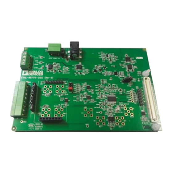
EVAL-AD7175-2SDZ
Rev. Pr.C | Page 1 of 12
EVAL-AD7175-2SDZ User Guide
GENERAL DESCRIPTION
The EVAL-AD7175-2SDZ evaluation kit features the
AD7175-2, a 24-bit, 250 kSPS analog-to-digital converter
(ADC) with integrated rail to rail analog input buffers, on-
board power supply regulation, and an external amplifier
section for amplifier evaluation. A 7 V to 9 V ac-to-dc adapter
is regulated to 5 V and 3.3 V; this supplies the
support components. The
to a USB port via the system demonstration platform (SDP)
EVAL-SDP-CB1Z
The
EVAL-AD7175-2SDZ
the
AD7175-2
device functionality via a user accessible register
interface and provides dc time domain analysis in the form of
waveform graphs, histograms, and associated noise analysis for
ADC performance evaluation.
ADP7118
3.3V LDO
REFOUT
IOVDD
REGCAP D
Buffered
Precision
1.8V
Reference
LDO
INT
REF
SERIAL
INTERFACE
& CONTROL
DIGITAL
FILTER
XTAL & INTERNAL
CLOCK OSCILLATOR
CIRCUITRY
DGND
XTAL1
XTAL2/CLKIO
Block Diagram
UG-AD7175-2
EVAL-AD7175-2SDZ
controller board.
evaluation software fully configures
ADP7104
5V LDO
USB
CS
SCLK
DIN
ADSP-BF527
DOUT/RDY
SYNC
PO W ER
ERROR
SDP-B
AD7175-2
and
board connects
LED
STATUS
Advertisement
Table of Contents

Related Manuals for Analog Devices EVAL-AD7175-2SDZ


Summary of Contents for Analog Devices EVAL-AD7175-2SDZ
-
Page 1: Features
20 μs Settling and Integrated Analog Input Buffers FEATURES GENERAL DESCRIPTION Full featured evaluation board for the AD7175-2 The EVAL-AD7175-2SDZ evaluation kit features the PC control in conjunction with the SDP (see EVAL-SDP-CB1Z AD7175-2, a 24-bit, 250 kSPS analog-to-digital converter from Analog Devices, Inc. -
Page 2: Table Of Contents
Functional Block Diagram .............. 1 Evaluation Board Software ...............7 Revision History ................2 Software Installation ..............7 EVAL-AD7175-2SDZ Quick Start Guide ........3 Launching the Software ..............7 Recommended Quick Start Guide ..........3 Software Operation ................8 Quick Start Noise Test ..............3 Overview of the Main Window ...........8... -
Page 3: Eval-Ad7175-2Sdz Quick Start Guide
Choose to automatically search for the drivers for the SDP-B board if prompted by the operating system. Launch the EVAL-AD7175-2SDZ software from the Analog Devices subfolder in the Programs menu. Figure 2. Hardware Configuration, Setting Up the EVAL-AD7175-2SDZ Rev. Pr.C | Page 3 of 12... -
Page 4: Evaluation Board Hardware
EVAL-AD7175-2SDZ User Guide EVALUATION BOARD HARDWARE DEVICE DESCRIPTION using the evaluation board. Full details for the EVAL-SDP-CB1Z are available on the Analog Devices website. AD7175-2 is a highly accurate, high resolution, multiplexed, HARDWARE LINK OPTIONS 2-/4-channel (fully differential/single-ended) Σ-Δ ADC. The... -
Page 5: Sockets And Connectors
3-pin, 3.81 mm pitch Contact External ac-to-dc adapter input for the DC power Kycon KLDX-SMT2- MOUSER 806- connectors, 2 mm EVAL-AD7175-2SDZ, 7 V to 9 V 0202-A KLDX-SMT20202A SMT power jack Analog input terminal block; wired Power socket block, Phoenix MC 1,5/ 8-G-3,81... -
Page 6: Power Supply Configurations
UG-AD7175-2 EVAL-AD7175-2SDZ User Guide Table 3. Power Supply Configurations Configuration Input Voltage Range Description Single Supply (Regulated) 7 V to 9 V The 7 V to 9 V input is regulated to 5 V for AVDD1/AVDD2 and 3.3 V for IOVDD. -
Page 7: Evaluation Board Software
AD7175-2SDZ EVAL-SDP-CB1Z are correctly connected to the PC. To launch the software, complete the following: From the Start menu, click Programs, Analog Devices, then EVAL-AD7175-2SDZ. The main window of the Figure 3. AD7175-2 User Account Control Permission Dialog Box software then displays (see Figure 7). -
Page 8: Software Operation
UG-AD7175-2 EVAL-AD7175-2SDZ User Guide SOFTWARE OPERATION Figure 7. Configuration Tab of the AD7175-2 Evaluation Board Software OVERVIEW OF THE MAIN WINDOW bypassed and so you can change the external reference voltage value here to ensure correct calculation of results on the The main window of the software displays the significant Waveform and Histogram tabs. -
Page 9: Waveform Tab (8)
EVAL-AD7175-2SDZ User Guide UG-AD7175-2 Channel Configuration Overview (6) Status Bar (7) This section shows the channel configuration including setup This section display status updates such as Analysis Completed and analog inputs. This allows for a quick check of how the and Reset Completed during software use as well as the ADC is setup. -
Page 10: Histogram Tab (19)
UG-AD7175-2 EVAL-AD7175-2SDZ User Guide affect the display of the channels and do not have any effect on CRC Error (17) the channel settings in the ADC register map. This LED icon illuminates when a cyclic redundancy check Display Units and Axis Controls(16) (CRC) error is detected in the communications between the software and the AD7175-2. -
Page 11: Register Map Tab (22)
EVAL-AD7175-2SDZ User Guide UG-AD7175-2 Figure 10. Register Map Tab of the AD7175-2 Evaluation Board Software REGISTER MAP TAB (22) down menu or directly entering a value into the number control on the right. Register Tree (23) Documentation (26) This control show the full register map in a tree control. Each... - Page 12 By using the evaluation board discussed herein (together with any tools, components documentation or support materials, the “Evaluation Board”), you are agreeing to be bound by the terms and conditions set forth below (“Agreement”) unless you have purchased the Evaluation Board, in which case the Analog Devices Standard Terms and Conditions of Sale shall govern. Do not use the Evaluation Board until you have read and agreed to the Agreement.
Need help?
Do you have a question about the EVAL-AD7175-2SDZ and is the answer not in the manual?
Questions and answers