Table of Contents
Advertisement
Quick Links
One Technology Way • P.O. Box 9106 • Norwood, MA 02062-9106, U.S.A. • Tel: 781.329.4700 • Fax: 781.461.3113 •
Evaluating the
FEATURES
Full-featured evaluation board for the
Graphic user interface software with frequency sweep
capability for board control and data analysis
Various power supply linking options
Standalone capability with serial I
microcontroller
Selectable system clock options including internal RC
oscillator or on-board 16 MHz crystal
APPLICATIONS
Electrochemical analysis
Impedance spectroscopy
Complex impedance measurement
Corrosion monitoring and protection equipment
Biomedical and automotive sensors
Proximity sensing
GENERAL DESCRIPTION
This user guide describes the
and the application software developed to interface with the device.
The
AD5933
is a high precision impedance converter system that
combines an on-board frequency generator with a 12-bit, 1 MSPS
analog-to-digital converter (ADC). The frequency generator
allows an external complex impedance to be excited with a
MCLK
OSCILLATOR
SCL
2
I
C
INTERFACE
SDA
REAL
IMAGINARY
REGISTER
REGISTER
1024-POINT DFT
AGND
PLEASE SEE THE LAST PAGE FOR AN IMPORTANT
WARNING AND LEGAL TERMS AND CONDITIONS.
AD5933
1 MSPS, 12-Bit Impedance Converter Network Analyzer
AD5933
2
C loading from on-board
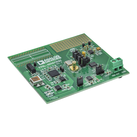
EVAL-AD5933EBZ
evaluation board,
EVALUATION BOARD BLOCK DIAGRAM
V
V
DD
DD
AVDD
DVDD
DDS
CORE
(27 BITS)
TEMPERATURE
SENSOR
AD5933
ADC
GAIN
(12 BITS)
LPF
DGND
Evaluation Board User Guide
known frequency. The on-board ADC samples the response
signal from the impedance, and an on-board DSP engine at each
excitation frequency processes the DFT. The
an internal temperature sensor with 13-bit resolution. The part
operates from a 2.7 V to 5.5 V supply. Other on-board components
include a
ADR423
for the separate analog and digital sections of the device and a
ADP3303
ultrahigh precision regulator to act as a supply to the
on-board universal serial bus controller that interfaces to the
AD5933. The user has the option to power the entire circuitry
from the USB port of a computer.
The evaluation board also has a high performance trimmed
16 MHz surface-mount crystal to act as a system clock to the
AD5933, if required. The various link options located around the
evaluation board are listed in Table 1. Interfacing to the
is through a USB microcontroller that generates the I
necessary to communicate with the AD5933. Interfacing to the
USB microcontroller is done through a Visual Basic® graphic user
interface located on and run from the PC. Complete specifications
for the
AD5933
from Analog Devices, Inc., and should be consulted in conjunction
with this user guide when using the evaluation board.
1.48V
DAC
VOUT
R
OUT
TRANSMIT SIDE
OUTPUT AMPLIFIER
RFB
VIN
I-V
VDD/2
Figure 1.
Rev. 0 | Page 1 of 28
3.0 V reference to act as a stable supply voltage
are available in the
AD5933
1.98V p-p
VDD/2
V
DD
V
DD
−
50kΩ
A1
+
47nF
50kΩ
A1, A2 ARE
AD8606
½
R
FB
20kΩ
−
20kΩ
A2
V
DD
+
50kΩ
50kΩ
UG-364
www.analog.com
AD5933
also contains
AD5933
2
C signals
data sheet available
1.98V p-p
Z
UNKNOWN
Advertisement
Table of Contents

Subscribe to Our Youtube Channel
Related Manuals for Analog Devices EVAL-AD5933EBZ


Summary of Contents for Analog Devices EVAL-AD5933EBZ
-
Page 1: Features
AD5933 is a high precision impedance converter system that from Analog Devices, Inc., and should be consulted in conjunction combines an on-board frequency generator with a 12-bit, 1 MSPS with this user guide when using the evaluation board. -
Page 2: Table Of Contents
UG-364 Evaluation Board User Guide TABLE OF CONTENTS Features ....................1 Performing a Frequency Sweep...........6 Applications..................1 Two Installation Frequently Asked Questions ....... 10 General Description ................. 1 Source Code for Impedance Sweep..........12 ... -
Page 3: Evaluation Board Hardware
Evaluation Board User Guide UG-364 EVALUATION BOARD HARDWARE TERMINAL BLOCK FUNCTIONS Table 1. Link Functions Link No. Default Location Function Option to remove external conditioning Option to remove external conditioning On-board, 16 MHz crystal connection, connects to Y2 SMB connected external clock Connects 5 V from USB to ADP3303 AVDD and DVDD power supply connector... -
Page 4: Getting Started
USB cable provided in the evaluation kit and run Install the evaluation board software in the default destination the USB hardware installation wizard after the evaluation folder path, C:\Program Files\Analog Devices\AD5933\ software is correctly installed (the hardware installation AD5933 Evaluation Software Rev 1.0 Setup (see Figure 4). -
Page 5: Connecting The Usb Cable
Evaluation Board User Guide UG-364 Choose the Analog Devices directory (see Figure 5). If the CONNECTING THE USB CABLE Analog Devices folder does not yet exist, create an Analog To connect the USB cable, use the following steps: Devices folder and add the program icon to this new folder. -
Page 6: Verifying The Links And Power Up The Evaluation Board
AD5933). The default link positions are outlined in Table 1, then click Finish. see this before continuing. To open the software, go to Start > Programs > Analog Devices > AD5933 and click AD5933 Evaluation Software. Figure 12 shows the graphic user interface program open and running successfully. - Page 7 Evaluation Board User Guide UG-364 Figure 12. AD5933 Evaluation Software Front Panel (Impedance Profile of 200 kΩ Resistor Displayed) • only R1 was chosen in the Calibration Impedance Choose the external clock as the system clock. Select section, that is, to measure the impedance of a 200 kΩ External clock in the System Clock section (see 2 in resistive impedance across frequency.
- Page 8 UG-364 Evaluation Board User Guide • • To automatically calculate the gain factor(s) for the Click Measure in the Internal Temperature section of the subsequent sweep, click Calculate Gain Factor. The evaluation board software front panel to take a reading evaluation software evaluates either a single midpoint from the on-board temperature sensor.
- Page 9 Evaluation Board User Guide UG-364 Each data entry corresponds to a single measurement Note that the phase measured by the AD5933 takes into (frequency) point; therefore, if the value for the number of account the phase introduced through the entire signal path, increments is programmed as 511 point, the array contains that is, the phase introduced through the output amplifiers, a single column of data with 512 data points, starting at the...
-
Page 10: Two Installation Frequently Asked Questions
UG-364 Evaluation Board User Guide TWO INSTALLATION FREQUENTLY ASKED Scroll to Universal Serial Bus controllers and expand the root directory (see Figure 19). When the AD5933 hardware is QUESTIONS correctly installed, each time the USB cable connecting the Q: How can I confirm that the hardware was correctly installed evaluation board to the computer is plugged in, the items on the PC? within the Universal Serial Bus controllers are refreshed. - Page 11 Figure 19 is a correct installation. If the same error message is encountered the second time, uninstall the device driver, uninstall the software, and contact Analog Devices applications support www.analog.com for further instructions regarding valid driver files.
-
Page 12: Source Code For Impedance Sweep
UG-364 Evaluation Board User Guide SOURCE CODE FOR IMPEDANCE SWEEP PROGRAM FREQUENCY SWEEP PARAMETERS INTO RELEVANT REGISTERS (1) START FREQUENCY REGISTER (2) NUMBER OF INCREMENTS REGISTER (3) FREQUENCY INCREMENT REGISTER PLACE THE AD5933 INTO STANDBY MODE. RESET: BY ISSUING A RESET COMMAND TO THE CONTROL REGISTER, THE DEVICE IS PLACED IN STANDBY MODE. -
Page 13: Evaluation Board Source Code Extract
Evaluation Board User Guide UG-364 EVALUATION BOARD SOURCE CODE EXTRACT ‘------------------------------------------------------------------------------------------------------- ‘Code developed using visual basic® 6. ‘Datatype range ‘Byte 0-255 ‘Double -1.797e308 to – 4.94e-324 and 4.94e-324 to 1.7976e308 ‘Integer -32,768 to 32767 ‘Long -2,147,483,648 to 2,147,483,647 ‘Variant‘...when storing numbers same range as double. When storing strings same range as string. ‘-------------------------------------- Variable Declarations ----------------------------------------- Dim ReadbackStatusRegister As Long 'stores the contents of the status register. - Page 14 UG-364 Evaluation Board User Guide ElseIf ((real > 0) And (img < 0)) Then theta = Atn(img / real) '4th quadrant theta = minus angle phase2 = ((theta * 180) / pi ) +360 ElseIf ((real < 0) And (img < 0)) Then theta = -pi + Atn(img / real) '3rd quadrant theta img/real is positive phase2 = (theta * 180) / pi...
- Page 15 Evaluation Board User Guide UG-364 SettlingTimebyte0 = 0F ‘15 cycles (decimal) = 0F hex SettlingTimebyte1 = 00 ’00 = X1 WritetToPart &H8B, SettlingTimebyte0 WritetToPart &H8A, SettlingTimebyte1 ‘-------------------------------------- PLACE AD5933 IN STANDBYMODE ---------------------------------------- ‘Standby mode command = B0 hex WritetToPart &H80, &HB0 '------------------------- Program the system clock and output excitation range and PGA setting----------- ‘Enable external Oscillator WritetToControlRegister2 &H81, &H8...
- Page 16 UG-364 Evaluation Board User Guide ImagineryDataLower = PortRead(&HD, &H97) ImagineryData = ImagineryDataLower + (ImagineryDataUpper * 256) 'The imaginary data is stored in a 16 bit 2's complement format. 'In order to use this data it must be converted from 2's complement to decimal format If ImagineryData <= &H7FFF Then ' Positive Data.
-
Page 17: Gain Factor Calculation
Evaluation Board User Guide UG-364 GAIN FACTOR CALCULATION The gain factor is then given by ⎛ ⎞ ⎛ ⎞ The code shown in the Evaluation Board Source Code Extract ⎜ ⎟ ⎜ ⎜ ⎟ ⎟ ⎜ ⎟ kΩ ⎛ ⎞ ⎠... -
Page 18: Impedance Measurement Tips
UG-364 Evaluation Board User Guide Label8.Caption = (Temperature - 16384) / 32# End If 're-assign variables used. TemperatureUpper = 0 TemperatureLower = 0 Temperature = 0 End Sub Calculate the gain factor when the largest response signal is IMPEDANCE MEASUREMENT TIPS presented to the ADC while ensuring that the signal is always This section outlines some of the workarounds for using the maintained within the linear range of the ADC over the impedance... - Page 19 Evaluation Board User Guide UG-364 Measuring Lower Excitation Frequencies The conventional DFT correlates the input signal against a series of test phasor frequencies to determine the fundamental signal AD5933 has a flexible internal DDS core and a digital-to- frequency and its harmonics. The frequency of the test phasor is analog converter (DAC) that together generate the excitation at integer multiples of a fundamental frequency given by the signal used to measure the impedance (Z...
- Page 20 UG-364 Evaluation Board User Guide For the AD5933 to analyze the impedance (Z ) at It is possible to accurately measure the 3 kHz signal using a lower UNKNOWN frequencies lower than ≈ 1 kHz, it is necessary to scale the system system clock of 4 MHz;...
- Page 21 Evaluation Board User Guide UG-364 Measuring the Phase Across an Impedance AD5933 parameters of interest are the magnitude of the impedance (|Z |) and the impedance phase (ZØ). The AD5933 returns a complex output code made up of a separate UNKNOWN measurement of ZØ...
- Page 22 UG-364 Evaluation Board User Guide Figure 29 shows the AD5933 system phase response calculated In addition, take care when using the arctangent formula when using a 220 kΩ calibration resistor (R = 220 kΩ, PGA = ×1) using the real and imaginary values to interpret the phase at and the repeated phase measurement with a 10 pF capacitive each measurement point.
-
Page 23: Evaluation Board Schematics And Artwork
Evaluation Board User Guide UG-364 EVALUATION BOARD SCHEMATICS AND ARTWORK Figure 31. EVAL-AD5933EBZ USB Schematic Rev. 0 | Page 23 of 28... - Page 24 UG-364 Evaluation Board User Guide Figure 32. EVAL-AD5933EBZ Schematic Rev. 0 | Page 24 of 28...
- Page 25 Evaluation Board User Guide UG-364 Figure 33. Linear Regulator on the EVAL-AD5933EB Evaluation Board Rev. 0 | Page 25 of 28...
-
Page 26: Ordering Information
Part Description Manufacturer Part Number C1 to C3 Capacitor, MR04, place holder Not applicable Not applicable Analog Devices issue 73017015 Capacitor, MR04, place holder, insert 2-wire wrap pins 10 μF tantalum capacitor, 10 V AVX Corporation TAJB106K016R 47 nF capacitor, 50 V, through hole, 10%, R1/8 W... -
Page 27: Related Links
Evaluation Board User Guide UG-364 RELATED LINKS Resource Description AD5933 1 MSPS, 12-bit impedance converter network analyzer AD9834 20 mW power, 2.3 V to 5.5 V, 75 MHz complete DDS ADF4001 200 MHz clock generator PLL ADuC7020 Precision analog microcontroller, 12-bit analog I/O, ARM7TDMI® MCU ADCMP601 Rail-to-rail, very fast, 2.5 V to 5.5 V, single-supply TTL/CMOS comparator in a 6-lead SC70 package ADP3303... - Page 28 By using the evaluation board discussed herein (together with any tools, components documentation or support materials, the “Evaluation Board”), you are agreeing to be bound by the terms and conditions set forth below (“Agreement”) unless you have purchased the Evaluation Board, in which case the Analog Devices Standard Terms and Conditions of Sale shall govern. Do not use the Evaluation Board until you have read and agreed to the Agreement.
Need help?
Do you have a question about the EVAL-AD5933EBZ and is the answer not in the manual?
Questions and answers