RGBlink X3 User Manual
Hide thumbs
Also See for X3:
- User manual (96 pages) ,
- Quick start manual (39 pages) ,
- User manual (76 pages)
Table of Contents
Advertisement
Quick Links
Advertisement
Table of Contents

Related Manuals for RGBlink X3


Summary of Contents for RGBlink X3
- Page 1 User Manua Article No: RGB-RD-UM- X3 E007 Revision No: V1.7...
-
Page 2: Table Of Contents
2.1 Plugging in Signals ..........................12 2.2 Plugging in Main Power ......................... 12 2.3 Turning on Your Product ........................12 2.4 Connect X3 and Computer ........................13 Chapter 3 Using Your Product ..........................14 3.1 XPOSE 2.0 Installation ..........................14 3.2 XPOSE 2.0 Operation ..........................17 3.2.1 Login in XPOSE .......................... - Page 3 3.2.4 Display Management ........................31 3.2.5 Layer Management ........................33 3.2.6 Preset Management ........................37 Chapter 4 Ordering Codes ............................40 4.1 Product Code .............................40 4.2 Module Code ............................. 40 4.2.1 Input Modules ..........................40 4.2.2 Output Modules ..........................40 4.2.3 Others ...............................40 Chapter 5 Support ..............................41 5.1 Contact Us ..............................
-
Page 4: Declarations
The period of guarantee begins on the date of transfer of risks, in the case of special systems and software on the date of commissioning, at latest 30 days after the transfer of risks. In the event of justified notice of compliant, RGBlink can repair the fault or provide a replacement at its own User Manual... -
Page 5: Operators Safety Summary
RGBlink. If the purchaser or a third party carries out modifications or repairs on goods delivered by RGBlink, or if the goods are handled incorrectly, in particular if the systems are commissioned operated incorrectly or if, after the transfer of risks, the goods are subject to influences not agreed upon in the contract, all guarantee claims of the purchaser will be rendered invalid. - Page 6 unit without the cover installed. Power Source This product is intended to operate from a power source that will not apply more than 230 volts rms between the supply conductors or between both supply conductor and ground. A protective ground connection by way of grounding conductor in the power cord is essential for safe operation.
-
Page 7: Installation Safety Summary
Installation Safety Summary Safety Precautions For all product installation procedures, please observe the following important safety and handling rules to avoid damage to yourself and the equipment. To protect users from electric shock, ensure that the chassis connects to earth via the ground wire provided in the AC power Cord. -
Page 8: Chapter 1 Your Product
Chapter 1 Your Product 1.1 In the Box 1 x Network Cable 1 x USB Cable 1 x AC Power Cord 1 x DVI Cable 1 x SDI Cable 1 x HDMI to DVI Cable 1 x Anti-static Bag 1 x DB9 to RJ11 Cable Note: AC Power Cable supplied as standard according to destination market. -
Page 9: Product Overview
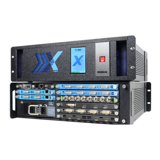
X3 offers six card cages that support various combinations of input and output cards for DVI, VGA, HDMI, CVBS, SDI and USB (for media files play) or video sources. Hundreds of additional video or graphic sources can be input to the X3 using the RGBlink AVDXP Matrix and Router. -
Page 10: Front Panel
1.2.1 Front Panel OLED Panel Show the input shot and output slot information, device status, COM. Version, IP address and serial address. POWER Power button, long push the button, the device can be boot up. Under normal running state, push the button once, the info shown on OLED can be refreshed once ;... -
Page 11: Rear Panel
1.2.2 Rear Panel Chassis Module Structure 2 output module slots Genlock interface 4 input module slots Power Switch and Power Module Communication ports Input Interface 4 input slots, supports input modules including DVI, VGA, HDMI, USB, CVBS, 4K@60HZ module and 12G-SDI. For details, please refer to Specification at the end of this document. -
Page 12: Dimension
Connect to the display device, video processor or matrix. Power Connection Power Switch Connect the windows control program and device upgrade. Power Interface AC:100-240V Power: Max 65W Power Supply Interface: IEC-3. 1.2.3 Dimension Following is the dimension of X3 for your reference: User Manual... -
Page 13: Chapter 2 Installing Your Product
Chapter 2 Installing Your Product 2.1 Plugging in Signals Connect signals to the product (ensure all the device are all power off first).Tighten connector screws/locks where provided. 2.2 Plugging in Main Power Connect IEC cable to device and plug into wall socket. Turn on power at wall socket. 2.3 Turning on Your Product Turn on the power switch on the real panel. -
Page 14: Connect X3 And Computer
COM. Versions. IP address and serial number. 2.4 Connect X3 and Computer Use network cable to connect the X3 and computer as the following picture show: Set the IP address of the computer and make sure the computer and the device are in same network range. -
Page 15: Chapter 3 Using Your Product
Chapter 3 Using Your Product 3.1 XPOSE 2.0 Installation Environment Requirements: Window Processor: 1 GHz or above 32 bit or 64 bit processor Memory: 4 GB or more Graphics: Support DirectX 9 128M or above (open AERO effect) Hard disk space: Above 16G (primary partitions, NTFS format) Monitor: Resolution must be 1920x1080 pixel or above (it can not display normally if the resolution is lower than 1920x1080) Operating system: Windows 7 or above (full version, not Ghost version or compact version) - Page 16 2. Click “Next”to install. 3. Click “Browse...” to select the XPOSE software install location. Click “Install”. 4. During installation, it will pop up the window of Install Shield Wizard for Virtual Com port. 5. Click “Next”. User Manual...
- Page 17 6. Then click “Install", as shown in the figure. Click “Finish” and complete the installation, as shown in the figure below. 7. Click “Finish”and is ready to run the XPOSE software. User Manual...
-
Page 18: Xpose 2.0 Operation
3.2 XPOSE 2.0 Operation 3.2.1 Login in XPOSE Double click this icon ,and enter the log on interface shown in the right: The initial language of XPOSE 2.0 is self adjusted based on the operation system language of the computer. If you want to change language, just click Language and choose one you need. -
Page 19: System Setting
3.2.2 System Setting Click to enter <System Setting>interface. Find Device : New version of XPOSE 2.0 is blank default in Find Device. Users are supposed to choose the device needed in Find Device. System Info: Check current software version and choose system language you need. - Page 20 Please note the keyboard area where allows to set short cut keys. If the setting goes wrong or no need for short cut keys to clear some keys or clear all. any more, click Clear: To clear some keys, the keys need to selected before hand.
- Page 21 Authorization Setting Click to open up the authorization entry. Authorization Setting is used to add and edit the user name and password for authorized users, as well as the permissions that users can operate. Authorization Status defaults to OFF, please Turn On Status for operation.
- Page 22 Edit: Edit user name and password already built. Delete: Delete user name and password already built. Authorization Set: Functions on XPOSE 2.0 on this computer that the users are allowed to operate. Click the green block to remove the function not to be permitted.
-
Page 23: Output | Input | Overview
Users can do settings to the port now. A red rectangle flashes around the chosen port when it is chosen. Resolution X3 supports resolution settings of output modules. Switch Mode: Manual/Auto Output Switch: ON/OFF Format Range: ALL/Board All Format Range: To set output resolution of all output modules to be the same. - Page 24 Format Type: Standard Type/Customize Standard Resolutions: Can be chosen from the list as shown in the right figure. Customize: Customize output resolution. Click output port and type in Width, Height and Refresh Rate. Standard Customize Genlock Set Status: Enable or disable the Genlock function by sliding the Genlock switch.
- Page 25 DE Switch: : Enable or disable the DE function by sliding the DE Switch and do settings with X, Y, width, height, line polarity and scene polarity. X3 output modules support OSD settings, please Turn ON Status first. Operation Mode: Single Output/Multiple Outputs...
- Page 26 After all settings done, click <Set> and the OSD will be displayed on the screen. Input Setting Click any input port, the board where the port locates is selected. Users can do settings to the port now. A red rectangle flashes around the chosen port when it is clicked.
- Page 27 DSK (Chroma Key) Users can perform chroma key on image video for the selected input port. Please turn on DSK switch and then do settings on transparency and RGB values. Input Port:Chosen port Preset: Select preset Basic Parameters DSK Setting: ON/OFF Operation Mode: Customize mode Transparent: Customize transparency Max/Min: Set maximum and minimum RGB...
- Page 28 LOGO Delete Logo: Clear logo set already Set Logo Status: Hide/Show Logo Source Merge For DVI and HDMI input module, X3 support s to customize layout to do signal merger. Channels:Select channel Layers:Select layer Merger Mode:10 types optional Source: Select signal source...
- Page 29 Scale X/Y:The starting horizontal and vertical position Width/Height : The horizontal and vertical size of scale. Crop Support cropping for position, height and width. Select USB input port and the interface is shown in the right. Property Setting Input Port:Chosen port Scale X/Y:The starting horizontal and vertical position Width/Height : The horizontal and vertical size of...
- Page 30 Input Port:Chosen USB port USB Video Player Setting: Can select play in order, random, single cycle and all cycle, switch to pre or next, pause or play, and read the video progress bar and time. USB Image Play Time: Click the image, it will display the setting interface, default time is 0s.
- Page 31 Fan Control X3 supports auto/manual setting for fan speed. Fan Speed: 0-100 adjustable Notice: To avoid insufficient heat dissipation, the recommended manual fan speed is not less than 30%. Backup Backup: Select ON or OFF to enable or disable backup Backup Mode: Set backup mode to Input Backup or Preset Backup.
-
Page 32: Display Management
Users can choose output resolution as shown in the figure. Mode Each mode is marked in different color and provided with fitted templates. Users can do operations like splice under different modes. X3:Presentation Mode (by default) , PST+PGM Mode, Rotation Mode and Edge Blending Mode optional. User Manual... - Page 33 Customize Container Click at the bottom of template list. Monitor Layout: Auto or Manual Steps of create container are as follows: 1. Fill in H Total/V Total and Row/Column,it will calculate H item and V item automatically. For example, if you would like to create a container with 2 rows and 2 columns and each display has a width of 1920 and a height of 540, the total width will be 3840 and the total height will be 1080.
-
Page 34: Layer Management
Display System X3 allows users to edit the name of the Display Area that has been created just click 3.2.5 Layer Management Layer Management is designed to manage the layer of each monitor. Click to enter the interface: Display Area When enter Layer Management interface, the window is blank. - Page 35 Layer Layer number : Numbers in the corner is to show how many layers at present allowed to put in the output. The number in the red rectangle on the right figure represents the number of layers that can be placed at the output.
- Page 36 Scale Alpha: Set the alpha, the adjustment range is 0~128 Position: Type in X/Y/Width/Height Crop Display Mode:Select Active or Freeze Mirror:Enable or disable the mirror function, default to Position: Type in X/Y/Width/Height Layer Movement Moving the mouse to drag the layer. Layer Remove Click the cross on the top right of the layer to...
- Page 37 Other Operation on Layer Use the tools bar on top of window to do such operations. Layer Layer to Top Paste Selected Backward Layer Forward Select All Cancel Selected Layer to Copy Selected Delete Selected Bottom Note:One signal occupies one layer (4K signal occupies four layers), signal can be dragged into the container repeatedly.
-
Page 38: Preset Management
3.2.6 Preset Management Preset Management is designed to switch bank (scene setting done in last step). Preset Management Mode: 1. Manual Mode 2. Schedule Mode 1. Manual Mode The chosen scene will be displayed in the main interface, and the PGM screen is in the first in the Bank Column. Take Setting Fade Time: The adjustment range is 0~10S Display: ON/OFF... - Page 39 Load Page Click Load Page, page with saved preset displays in green. Select one preset and then load this preset, the page turns in red. Script Click<Script>, fill in the file name and click “Save”,the file can be seen in the <Load Script> Click “Load”...
- Page 40 2. Schedule Mode This mode is designed to set auto bank (scene/preset) switch. Steps are as follows: 1. Turn on “Schedule Mode” 2. Choose “Times Loop” in Loop Mode 3. Choose the BANK 4. Fill in the “Duration” 5. Click “OK” Users can click to edit and to delete.
-
Page 41: Chapter 4 Ordering Codes
Chapter 4 Ordering Codes 4.1 Product Code 310-0003-11-0 4.2 Module Code 4.2.1 Input Modules 190-0003-01-0 Quad 2K DVI Input Module 190-0003-05-0 Quad 2K HDMI Input Module 190-0003-06-0 Octuple CVBS Input Module 190-0003-11-0 4K@30Hz Input Module 190-0003-14-0 Quad 3G-SDI Input Module (De-interlace) 190-0003-15-0 4K@60Hz Input Module (DVI/HDMI 1.4/HDMI 2.0/DP 1.2) 190-0003-17-0... -
Page 42: Chapter 5 Support
Chapter 5 Support 5.1 Contact Us User Manual... -
Page 43: Chapter 6 Appendix
Chapter 6 Appendix 6.1 Specification DVI Input Module Interface Appearance Dimension 216*200*20(mm) Number of Connectors Connector DVI-I Input Resolution SMPTE 480i | 576i | 720p@50/59.94/60 | 1080i@50/59.94/60| 1080p@50/59.94/60 VESA 800×600@60 |1024×768@60 |1280×768@60 | 1280×1024@60 | 1600×1200@60 | 1920×1080@60 Format Standard Single Link DVI Color Space 8bit RGB... - Page 44 Connectors Connector HDMI-A Input Resolution SMPTE 720P@60 | 1080P@60 |2160@60 VESA 800×600@60 | 1024×768@60 | 1280×720@60 | 1280×800@60 | 1366×768@60 | 1400×1050@60 | 1600×1200@60 | 1920×1080@60 | 2048×1152@60 | 2560×812@60 | 2560×816@60 | 2560×1600@60 | 3840×1080@60|3840×2160@23.98/24/25/29.97/30/50 /60 | 4096×2160@60 | 7680×1080@60 Format Standard HDMI 2.0 Color Space...
- Page 45 Supported Standard SMPTE ST 2082-1, SMPTE ST 2081-1, SMPTE ST 424, SMPTE ST 292-1, SMPTE 274M SMPTE 296M | SMPTE 272M | SMPTE 299M | SMPTE ST 259, DVB-ASI,MADI Color Space 10bit YUV 4:2:2 Indicator Light White Light:normal signal connection;Unlit:no signal connection HDBaseT Input Module Interface Appearance...
- Page 46 Indicator Light White Light:normal signal connection;Unlit:no signal connection 4K@30 Input Module Interface Appearance Dimension 216*212*20(mm) Number of Connectors Connector DVI-I | HDMI-A | DisplayPort Input Resolution SMPTE 480i | 576i | 720p@50/59.94/60 | 1080i@50/50.94/60 | 1080p@ 23.94/24/25/30/50/59.94/60 | 2160p@23.94/24/25/30 VESA 800×600@60 | 1024×768@60 | 1280×768@60 | 1280×1024@60 | 1600×1200@60 |1920×1080@60 | 1920×1200@60 | 2048×1152@60 | 2560×1440@60 |...
- Page 47 10 bit RGB/YUV 4:2:0/YUV 4:2:2/YUV 4:4:4 12 bit RGB/YUV 4:2:0/YUV 4:2:2/YUV 4:4:4 Indicator Light White Light:normal signal connection;Unlit:no signal connection DVI Output Module Interface Appearance Dimension 216*200*20(mm) Number of Connectors Connector DVI-I Signal Level TMDS pw, 165MHz bandwidth Output Resolution SMPTE 720p@50/59.94/60| 1080p@50/59.94/60 VESA...
- Page 48 Number of Connectors Connector HDMI-A Output Resolution SMPTE 480i | 576i | 720p50/59.94/60 | 1080i50/59.94/60 | 1080P50/59.94/60 VESA 800×600@60 | 1024×768@60 | 1280×768@60 | 1280×1024@60 | 1600×1200@60 | 1920×1080@50/60 Format Standard HDMI 1.3 Color Space 8 bit RGB 10 bit RGB 12 bit RGB Indicator Light White Light:normal signal connection;Unlit:no signal connection...
-
Page 49: Installing Options
3 years parts and labor warranty 6.2 Installing Options X3 supports replaceable input and output optional modules, user can install or replace the optional module according to actual need. Take X3 for example, the specific installation steps are as follows: Install the Optional Module... - Page 50 1. Unscrew the 2 captive screws in input modules block, and pull out the input module block, as shown in figure: Captive Screw 2. Install the input module: For the whole PCB input module with DVI or HDMI interface, fix the input module on the plate with 2 M3*4 flat screws, also need to install the 2G Micro SD card.
- Page 51 Micro SD card DVI input module: For the joined PCB input module with CVBS, HDMI, VGA, USB or SDI interface, fix the input module on the plate with 2 M3*4 flat screws and 2 M3*4 round head screws. User Manual...
- Page 52 HDMI input module: VGA input module: CVBS input module: USB input module: User Manual...
- Page 53 3. Fix the input module block with fixed screws, as shown in figure: 4. Push the input modules into the device along the slide rail, and screw the captive screws, as shown in figure: User Manual...
-
Page 54: Terms & Definitions
Note: The install steps of output module installation and input/output module replacement are the same as above. 6.3 Terms & Definitions ● RCA: Connector used primarily in consumer AV equipment for both audio and video. The RCA connector was developed by the Radio Corporation of America. ●BNC: Stands for Bayonet Neill-Concelman. - Page 55 HD-SDI. ●6G-SDI: Standardized in SMPTE ST-2081 released in 2015, 6Gbit/s bitrate and able to support 2160p@30. ●12G-SDI: Standardized in SMPTE ST-2082 released in 2015, 12Gbit/s bitrate and able to support 2160p@60. ●U-SDI: Technology for transmitting large-volume 8K signals over a single cable. a signal interface called the ultra high definition signal/data interface (U-SDI) for transmitting 4K and 8K signals using a single optical cable.
- Page 56 60 Hz or 4K UHD (3840 × 2160) at 120 Hz with 30 bit/px RGB color and HDR. 4K at 60 Hz 30 bit/px RGB/HDR can be achieved without the need for DSC. ● Multi-mode Fiber: Fibers that support many propagation paths or transverse modes are called multi-mode fibers, generally have a wider core diameter and are used for short-distance communication links and for applications where high power must be transmitted.
- Page 57 USB version and connectors figure: Type Type B Mini Mini Micro- Micro Type C USB 2.0 USB 3.0 3.1&3.2 ●NTSC: The colour video standard used in North America and some other parts of the world created by the National Television Standards Committee in the 1950s. NTSC utilizes an interlaced video signals. ●PAL: Phase Alternate Line.
- Page 58 ●Dante AV: The Dante protocol was developed for and widely adopted in audio systems for the transmission of uncompressed digital audio on IP based networks. The more recent Dante AV specification includes support for digital video. ●NDI: Network Device interface (NDI) is a software standard developed by NewTek to enable video-compatible products to communicate, deliver, and receive broadcast quality video in a high quality, low latency manner that is frame-accurate and suitable for switching in a live production environment over TCP (UDP) Ethernet based networks.
- Page 59 are triggers or commands sent over twisted pair cables, typically using 5pin DIN connectors . ●OSC: The principle of Open Sound Control (OSC) protocol is for networking sound synthesizers, computers, and multimedia devices for musical performance or show control. As with XML and JSON, the OSC protocol allows sharing data.
-
Page 60: Revision History
computer monitors the most commonly used colour bars are two rows of reversed colour bars ●Seamless Switching: A feature found on many video switchers. This feature causes the switcher to wait until the vertical interval to switch. This avoids a glitch (temporary scrambling) which often is seen when switching between sources. - Page 61 Update XPOSE 2.0 operation Aster All information herein is Xiamen RGBlink Science & Technology Co Ltd. excepting noted. is a registered trademark of Xiamen RGBlink Science & Technology Co Ltd. While all efforts are made for accuracy at time of printing, we reserve the right to alter otherwise make change without notice.
Need help?
Do you have a question about the X3 and is the answer not in the manual?
Questions and answers