
Related Manuals for Advantech FWA-3051


Summary of Contents for Advantech FWA-3051
- Page 1 User Manual Revision 1.0 FWA-3051 1U Network Appliance Copyright 2024 Advantech Co. Ltd. All rights reserved.
-
Page 2: Table Of Contents
..................................42 UMPER SETTINGS Jumper and switch setting ................................42 BIOS S ..................................43 ETUP 4.2.1 BIOS Defaults ................................43 4.2.2 BIOS Setup Menu ................................ 43 4.2.3 Main Setup Menu................................ 45 Copyright 2024 Advantech Co. Ltd. All rights reserved. Page 2... - Page 3 5.5.1 Sensor List ..................................71 5.5.2 Threshold Based Sensors ............................77 5.5.2.1 Voltage Sensors ............................... 78 5.5.2.2 Temperature Sensors ............................79 5.5.2.3 Current Sensors ..............................80 5.5.2.4 PSU ....................................80 Copyright 2024 Advantech Co. Ltd. All rights reserved. Page 3...
- Page 4 Table 5.5-1 BMC Sensor list Table 5.5-2 Threshold based sensor event data format. Table 5.5-3 Threshold based sensor supported events. Table 5.5-4 Voltage Sensor list Table 5.5-5 Temperature Sensor list Copyright 2024 Advantech Co. Ltd. All rights reserved. Page 4...
- Page 5 Figure 4.4-2 BIOS Setup Menu ................................64 Figure 4.4-3 BIOS Setup Menu ................................65 Figure 5.1-1 Connector and Jumper Location ..........................67 Figure 5.2-1 Serial Console port PIN definition ......................... 68 Copyright 2024 Advantech Co. Ltd. All rights reserved. Page 5...
-
Page 6: How To Use This Manual
Copyright and trademarks The documentation and the software included with this product are copyrighted by Advantech Co., Ltd. Advantech Co., Ltd. reserves the right to make improvements in the products described in this manual at any time without notice. No part of this manual may be reproduced, copied, translated or transmitted in any form or by any means without the prior written permission of Advantech Co., Ltd. -
Page 7: Conventions Used In This Manual (Warnings & Cautions)
ATTENTION! Des précautions sont incluses pour vous aider à éviter d'endommager le matériel ou de perdre des données. Note! Notes provide additional information. Remarque! Les notes fournissent des informations supplémentaires. Copyright 2024 Advantech Co. Ltd. All rights reserved. Page 7... -
Page 8: Product Warranty
Because of Advantech’s high quality-control standards and rigorous testing, most of our customers never need to use our repair service. If an Advantech product is defective, it will be repaired or replaced at no charge during the warranty period. For out of-warranty repairs, you will be billed according to the cost of replacement materials, service time and freight. -
Page 9: Products/Skus That This Manual Covers
Products/SKUs that this Manual covers Figure 0-1 Revision list Revision History Table 0-1 Revision list Date Revision Modifications 2024-01-10 Initial version Copyright 2024 Advantech Co. Ltd. All rights reserved. Page 9... -
Page 10: Related Manuals & Quick Start Image
Redfish user guide that corresponds to the major version number (the first digit of the version information.) https://www.advantech.com/emt/support/details/manual?id=1-27WSW6T Advantech Linux Platform Software Guide Please contact your Advantech representative if you reference to the following document(s) and image(s). Advantech QuickStart Linux Image Getting Started Guide Quick Start Linux Image Copyright 2024 Advantech Co. -
Page 11: Getting Started
National Electrical Code and NFPA 75. 22. RESTRICTED ACCESS AREA: The equipment should only be installed in a Restricted Access Area. 23. DISCLAIMER: This set of instructions is given according to IEC 704-1. Advantech disclaims all responsibility for the accuracy of any statements contained herein. - Page 12 20. Si des émetteurs-récepteurs optiques sont utilisés pour être connectés à des connecteurs SFP+, seuls des émetteurs-récepteurs optiques de classe I laser certifiés CDRH doivent être utilisés. (Demande de certificat UL). Copyright 2024 Advantech Co. Ltd. All rights reserved. Page 12...
-
Page 13: Declaration Of Conformity
22. ZONE D'ACCES RESTREINTE: L'équipement ne doit être installé que dans une zone d'accès restreint. 23. AVERTISSEMENT: Cet ensemble d'instructions est donné conformément à la CEI 704-1. Advantech décline toute responsabilité quant à l'exactitude des déclarations contenues dans ce document. 2.2 Declaration of Conformity 2.2.1 FCC Class A... - Page 14 7. 请在安装前确保设备放置在可靠的平面上,意外跌落可能会导致设备损坏。 8. 设备外壳的开口是用于空气对流,从而防止设备过热。请不要覆盖这些开口。 9. 当您连接设备到电源插座上前,请确认电源插座的电压是否符合要求。 10. 电源插座应接地。 11. 请将电源线安置在人们不易绊到的位置,并不要在电源在线覆盖任何杂物。 12. 设备上电前,将设备框架接地。对于接地线,需要绿色和黄色绝缘,导体的横截面积必须大于 0.75mm2 或 18 AWG。 13. 请注意设备上的所有警告和注意标语。 14. 如果长时间不使用设备,请将设备与电源插座间的电线断开,避免设备被超目标电压波动损坏 15. 请不要让任何液体流入通风口,以免引起火灾或者电路短路。 16. 请不要自行打开设备。为了确保您的安全,请由经过认证的工程师来打开设备。 17. 如遇下列情况,请由专业人员来维修: ◼ 电源线或者插头损坏; ◼ 设备内部有液体流入; Copyright 2024 Advantech Co. Ltd. All rights reserved. Page 14...
-
Page 15: Ce Mark
électromagnétique 2014/30 / UE, Directive sur la sécurité 2014/35 / UE. Note! The equipment is operated and maintained only by professionals Remarque!L'équipement est exploité et entretenu uniquement par des professionnels Copyright 2024 Advantech Co. Ltd. All rights reserved. Page 15... -
Page 16: Unpacking
2.3 Unpacking The FWA-3051 is packaged inside a single carton, collectively referred to as the “box” in the remainder of this document. When opening the box, you will find the FWA-3051 embedded in protective foam and the accessory box embedded to the foam. Remove the accessory box first and then pull out the unit including the protective foam using both hands. -
Page 17: Installation And Configuration
M4x8L type screws for 2 post rack mount kit 2.4 Installation and Configuration The FWA-3051 is provided as a pre-configured system with a SoC CPU already installed. If you happen to procure a barebone system or need to install additional components in the FWA-3051 for any other reason, please refer to Section 4.3. -
Page 18: Installation Via Serial Console
An RS232-to-RJ45 console cable is provided in the box. If you've misplaced it or need additional cables, make sure to use the appropriate serial console cable to connect the engineer’s PC to the FWA-3051's RJ45 serial port (Figure 2.4-3). - Page 19 If you intend to use PuTTY on a PC running Windows OS. The following of this section describes how to configure PuTTY on a Windows platform for connection with the FWA-3051 serial console as a reference. Otherwise, feel free to skip these steps if you have another preferred method. Other terminal programs may be used in a similar way as well.
- Page 20 Also, confirm that the OS could output to the serial console port. If you are using a Linux system, please refer to the “Common IPMI User Manual (Section 2.3)”. Copyright 2024 Advantech Co. Ltd. All rights reserved. Page 20...
- Page 21 Figure 2.4-5 PuTTY Session Configuration Select “Serial” for connection type. Figure 2.4-6 PuTTY Serial Configuration Copyright 2024 Advantech Co. Ltd. All rights reserved. Page 21...
- Page 22 Click the “Open” button and a PuTTY terminal screen will be displayed. If you wish to retain the configuration for future use, click the “Save” button. Figure 2.4-8 PuTTY Keyboard Settings Copyright 2024 Advantech Co. Ltd. All rights reserved. Page 22...
-
Page 23: Installation Via Ikvm
2.4.3 Installation via iKVM The FWA-3051 is equipped with Out-of-band (OOB) BMC that features a Web UI, providing a wide range of configuration options, including iKVM for graphic OS installations. To initiate, set up the BMC IP within the BIOS (please reference to Section 4.4.1.1) and then access it... -
Page 24: Rackmount Kit Installation
Rackmount Kit Installation Rack mount kit installation instruction: Align the holes on the rack mount bracket with the holes on the sides of FWA-3051. Insert screws through the holes in the rack mount bracket and into the corresponding holes on appliance. - Page 25 4 Post rack: Copyright 2024 Advantech Co. Ltd. All rights reserved. Page 25...
- Page 26 Copyright 2024 Advantech Co. Ltd. All rights reserved. Page 26...
- Page 27 Figure 2.4-11 2 and 4 Post Rack Mount Installation Copyright 2024 Advantech Co. Ltd. All rights reserved. Page 27...
-
Page 28: Powering On
Before connecting the FWA-3051 to the power outlet, ensure that the power rating of the outlet matched that of the FWA-3051’ PSU. Also, verify the primary circuit and all power distribution in not overloaded. Inrush current and steady state power specifications for the FWA-3051 can be found at the label under the bottom of the unit. -
Page 29: Product Specification
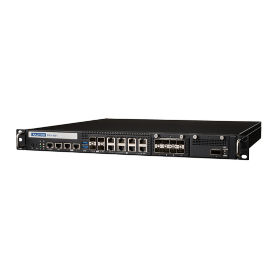
3. Product Specification 3.1 Overview FWA-3051 is 1U network appliance which is powered by Intel® Xeon® D-2700/D-2800 Series Processor Family. The Intel® Xeon® D-2700/D-2800 Series Processor is integrated with Intel Quick Assist Technology to increases encrypted packet throughput. FWA-3051 platform integrates 1G/10GbE wired networking ports, IPMI interfaces and unique 2 NMC expansion. - Page 30 Figure 3.2-2 System Rear Panel Copyright 2024 Advantech Co. Ltd. All rights reserved. Page 30...
- Page 31 • Supporting R-DIMM and U-DIMM • System Fan System fan module x4 • Air-duct The air duct covers CPU Heatsink as air flow tunnel • 2.5”HDD 2.5”HDD/SSD 2x 2.5”HDD/SSD holder Copyright 2024 Advantech Co. Ltd. All rights reserved. Page 31...
- Page 32 The FWA-3051 supports an array of status LEDs and buttons at left side of system front panel. Figure 3.2-4 Front Buttons Table 3.2-2 Status LEDs Software Software No. or Icon Description Name Controllable Controllable Button with LED ○ 1 Power LED...
-
Page 33: System Memory
3.2.2 System Memory A total of 4x DDR4 DIMMs are supported on the FWA-3051. One DIMM socket per DDR4 Channel with total 4x DDR4 Channels supported by Intel Xeon® D D-2700 and D-2800 series processor. The FWA-3051 supports up to 128GB of DDR4 UDIMM or up to 256GB of ECC DDR4 RDIMM (3200/2933/2667 MHz in 4 DIMM slots.) - Page 34 Figure 3.2-10 Seating the DIMM in the Socket 6. In case you want to install another DIMM, repeat steps 1 to 5 accordingly. Copyright 2024 Advantech Co. Ltd. All rights reserved. Page 34...
-
Page 35: Product Versions/Ordering Information
3.3 Product Versions/Ordering Information The FWA-3051 is available in the following standard configurations. Contact your Advantech representative for availability of other configuration options. Table 3.3-1 Available Product Versions Model Name Configurations Peripherals Power Adapter 2x M.2 Slots for 1U form-factor, single Intel D-... -
Page 36: Technical Specifications
3.4 Technical Specifications Table 3.4-1 Datasheet Copyright 2024 Advantech Co. Ltd. All rights reserved. Page 36... -
Page 37: Processor(S)
30MB 2933 MHz 117W Advantech is one of the first companies to adopt the latest Intel Xeon® D-2700 and D-2800 series to power its latest SD-WAN platforms, providing new capabilities and generational improvements to performance and power-efficiency. The new CPU architecture provides up to 2x performance uplift in networking packet processing, giving much higher data throughput that’s ready to scale with business needs. -
Page 38: Tpm
This feature is not available. 3.4.6 Internal Storage Two M.2 2280 SSDs are supported on the FWA-3051 located at each beside the memory slots and 2.5”HDD/SSD holder, M.2 socket location details may refer to Figure 3.2 3 Additional two 2.5”HDD/SSDs are also supported on the FWA-3051 with SATA3 interface and located in left side of inside chassis near with SATA port connector, details may refer to Figure 3.2 3. -
Page 39: Advanced Platform Management
For a detailed description of Advanced Platform Management features, please contact Advantech representative directly to obtain the FWA-3051 BMC specification. Additionally, appendix 5.6 provides the FWA-3051 sensor list and information on Threshold-based sensors. Copyright 2024 Advantech Co. Ltd. All rights reserved. -
Page 40: Power Supply(S)
3.4.9 Power Supply(s) The FWA-3051 supports 300W 1+1 redundant AC CRPS power supply. Power-rating and technical specification for the power supply can be found in Appendix 5.4. Caution! DO NOT remove the PSU before unplugging the power cable (power cord). -
Page 41: Advanced Platform Features
Physical Security CASE_INTRUSION | General Chassis intrusion | Deasserted 3.6 Available Accessories and Related Products The following accessories are available for ordering. Please contact your Advantech representative for a list of available and supported peripherals such as memory modules and M.2 SSDs. -
Page 42: Configuration And Service
ME_FLASH ME Flash connector JCMOS1 CMOS clear header UMPER AND SWITCH SETTING Location Function 1-2 (DEFAULT) Normal ME_FLASH ME Overwrite 1-2 (DEFAULT) Normal JCMOS1 CMOS Clear Figure 4.1-1 Jumper Location Copyright 2024 Advantech Co. Ltd. All rights reserved. Page 42... -
Page 43: Bios Setup Menu
4.2.2 BIOS Setup Menu This section describes the FWA-3051’s UEFI BIOS based on AMI’s APTIO V BIOS. Users can modify BIOS settings and control the special features of the FWA-3051 using the BIOS setup menu. Please note that Advantech supports shipping the FWA-3051 with custom BIOS defaults to simplify the deployment and integration for our customers. - Page 44 Figure 4.2-2 BIOS Setup Screen Organization Copyright 2024 Advantech Co. Ltd. All rights reserved. Page 44...
-
Page 45: Main Setup Menu
Please reference “Common BIOS User Manual” https://www.advantech.com/zh-tw/support/details/manual?id=1-2F8TKW5 4.2.4 Platform Setup Menu Here only described “SW Button Configuration” and “SW GPIO Configuration”. Please reference “Common BIOS User Manual” Figure 4.2-3 Platform Setup Main screen Copyright 2024 Advantech Co. Ltd. All rights reserved. Page 45... -
Page 46: Sw Button Configuration
Table 4.2-1 Platform Setup: SW Button Configuration Menu Items Setup item Access / Options Description Sleep Button / SW Button Set the SW Button as Sleep Button or Driver Driver / Mode mode or disable it. Disabled Copyright 2024 Advantech Co. Ltd. All rights reserved. Page 46... -
Page 47: Sw Gpio Configuration
“South Bridge” and “North Bridge” are legacy terms and do not represent the silicon implementation anymore. However, those terms are kept consistent with previous products to allow users to navigate more easily. The sub menus are described on the following pages. Copyright 2024 Advantech Co. Ltd. All rights reserved. Page 47... - Page 48 Figure 4.2-6 Hardware Configuration Menu Copyright 2024 Advantech Co. Ltd. All rights reserved. Page 48...
-
Page 49: Hardware Setup: Cpu Configuration
Displays information on the Display only information processor installed Intel VT-x Technology L1 code Cache L2 Cache L3 Cache Enable Enables Hyper Threading (Software Method to Hyper-Threading Enable/Disable Logical Processor threads) Disable Copyright 2024 Advantech Co. Ltd. All rights reserved. Page 49... -
Page 50: Hardware Setup: North Bridge Configuration
Disable 1A4h [3]). 4.2.5.2 Hardware Setup: North Bridge Configuration This menu allows the configuration of the memory controller and related features of the SoC. Figure 4.2-8 North Bridge Configuration Menu Copyright 2024 Advantech Co. Ltd. All rights reserved. Page 50... - Page 51 Select to enable / disable Patrol Patrol Scrub Scrub Support Enable at End of POST Enable Data Scrambling Select to auto to enable the for DDR4/5 Scrambler Disable Figure 4.2-9 PCI Express Ports Configuration Menu Copyright 2024 Advantech Co. Ltd. All rights reserved. Page 51...
-
Page 52: Pci Express Ports Configuration
This menu contains settings for the South Bridge for related SATA and USB and ACPI setting etc. Figure 4.2-10 Hardware Setup: South Bridge configuration Table 4.2-6 Hardware Setup: South Bridge Configuration Menu Items Group Setup item Access / Options Description SATA Select sub-menu. Hardware Configuration Copyright 2024 Advantech Co. Ltd. All rights reserved. Page 52... - Page 53 Table 4.2-7 Hardware Setup: SATA configuration Menu Items Feature Default Description Disabled SATA Controller 1 Enable or Disable SATA Controller Enabled AHCI This will configure SATA as RAID or SATA Mode RAID AHCI. Copyright 2024 Advantech Co. Ltd. All rights reserved. Page 53...
- Page 54 AHCI. SATA Port 0 Display only SATA Port 1 Display only Show current SATA devices in use on the FWA-3051 SATA Port 2 Display only SATA Port 4 Display only Copyright 2024 Advantech Co. Ltd. All rights reserved. Page 54...
-
Page 55: Acpi Setting
None Auto configuration Disabled Configuration Enables or Disables System ability Enabled Enable to Hibernate (OS/S4 Sleep State). None Hibernation This option may not be effective Disabled with some operating systems Copyright 2024 Advantech Co. Ltd. All rights reserved. Page 55... -
Page 56: Runtime Error Logging
Hardware Setup: Runtime Error logging configuration Table 4.2-9 Hardware Setup: Runtime Error logging Menu Items Group Setup item Access / Options Description Enabled System error enabling and logging None System Errors Disabled setup option Auto Copyright 2024 Advantech Co. Ltd. All rights reserved. Page 56... - Page 57 Enable/Disable VMD in this Stack Disabled ports Enabled Enable/Disable None Enable/Disable VMD in this Stack VMD for IOU0 Disabled Enabled Enable/Disable None Enable/Disable VMD in this Stack VMD for IOU4 Disabled Copyright 2024 Advantech Co. Ltd. All rights reserved. Page 57...
-
Page 58: Server Mgmt Setup Menu
4.2.7 Setup POST & Boot Menu Users can configure the system boot priority settings via the boot page. Please reference “Common BIOS User Manual”. (Note: FWA-3051 supports UEFI mode only; there is no legacy mode. CSM is not supported in FWA-3051 series) Copyright 2024 Advantech Co. -
Page 59: Security Setup
Allows users to configure the system a password Please reference “Common BIOS User Manual”. 4.2.9 Save & Exit Menu Allows users to store BIOS configuration results and exit. Please reference “Common BIOS User Manual”. Copyright 2024 Advantech Co. Ltd. All rights reserved. Page 59... -
Page 60: Installing Components
4.3.5 2.5” SSD Installation The FWA-3051 support two 2.5” SSD devices, and insert 2.5” disk following below figures steps by steps and then tight the screws and put it back to chassis with cables connection. - Page 61 2. Take out 2.5” SSD holder 3. Take SATA cables and screws from accessoby box 4. Tight screws with SSD devices 5. Put it back to chassis and connect cables Copyright 2024 Advantech Co. Ltd. All rights reserved. Page 61...
-
Page 62: Install/Remove Nmc
4.3.6 Install/Remove NMC FWA-3051 supports two PCIe x8 Network Mezzanine Cards (NMCs) slot in right side of front panel. Insert NMC alone with guiding rail and fasten it by thumbs screws. Figure 4.3-1 NMC Installation Copyright 2024 Advantech Co. Ltd. All rights reserved. -
Page 63: Firmware Upgrades
4.4 Firmware Upgrades The FWA-3051 is equipped with BMC (Baseboard Management Controller) functionality. Firmware upgrades can be performed through BMC. First, you need to set the BMC IP address. The firmware can be upgraded using either the BMC Web interface or the ipmitool utility. Here are the instructions: 4.4.1 How to access the BMC Web (Node Explorer)? - Page 64 2. Choose "BMC network configuration". Figure 4.4-2 BIOS Setup Menu 3. Set "Configuration Address" -> "Static", and then key in the IP address, subnet mask, gateway and other relevant network. Copyright 2024 Advantech Co. Ltd. All rights reserved. Page 64...
-
Page 65: How To Upgrade The Firmware Via Bmc Web (Node Explorer)
Section 3.2.4. 4.6 On board NIC’s ACT LED behavior FWA-3051 on board was designed with 4 Gbe NICs came from E823-C of SOC, and the NIC’s ACT LED with some conditions to trigger it, the details describe as below: Copyright 2024 Advantech Co. Ltd. All rights reserved. -
Page 66: On Board Nic's Lan Bypass Setting (Platform Reset)
4.7 On board NIC’s LAN bypass setting (platform reset) FWA-3051 on board was designed with 4 Gbe NICs which support 2 segment LAN bypass, and the bypass controlled by 8051 MCU and support 4 events to setup bypass behaviors as bypass or non- bypass or disconnect, the events as below, and all are work except “platform reset”... -
Page 67: Appendix
SATA connector#2 SATA connector#3 SATA connector#4 CN11 SATA power connector CN14 SATA/LCM power connector CN15 VROC connector CN33 SPI TPM connector System reset button System power button Software define button Copyright 2024 Advantech Co. Ltd. All rights reserved. Page 67... -
Page 68: Serial Console Cable Pin Configuration
Table 5.2-1 Connector and Jumper List Connector X1 (DB9) X2(RJ45) Pin assignment 5.3 BIOS Post code Please refer to the BIOS POST Codes Table in the document linked below: https://www.advantech.com/zh-tw/support/details/manual?id=1-2F8TKW5 Copyright 2024 Advantech Co. Ltd. All rights reserved. Page 68... -
Page 69: Power Supply Specification
5.4 Power Supply Specification The FWA-3051 is available with different power supply options. The specifications for the available power supplies on the standard product SKUs are listed below. Please consult your Advantech representative for other power supply options. Table 5.4-1 300W AC Power Supply Specification... - Page 70 AS/NZS CISPR 22 (Australia / New Zealand) GB 9254 – (EMC) Certification (China) GB 17625.1 - (Harmonics) CNCA Certification (China) Current Limit (OCP) Over Voltage Protection (OVP) Protection Over Temperature Protection (OTP) Short Circuit Protection (SCP) Copyright 2024 Advantech Co. Ltd. All rights reserved.
-
Page 71: Sensors
Progress sensor CASE_INTRUSION IPMI Physical Security sensor SESSION_AUDIT IPMI Session Audit sensor CPU_PRSNT CPU presence sensor C0_DIMM_A1_PRSNT DIMM module presence sensor DIMM module C0_DIMM_B1_PRSNT presence sensor C0_DIMM_C1_PRSNT DIMM module presence sensor Copyright 2024 Advantech Co. Ltd. All rights reserved. Page 71... - Page 72 PAY_12-VOL Payload Power voltage 12V SB_12-VOL Standby Power voltage 12V PAY_5-VOL Payload Power voltage 5V SB_5-VOL Standby Power voltage 5V PAY_3_3-VOL Payload Power voltage 3.3V SB_3_3-VOL Standby Power voltage 3.3V Copyright 2024 Advantech Co. Ltd. All rights reserved. Page 72...
- Page 73 CPU PVCCANA Power voltage 1.0V PAY_1_0_VR_I350 Intel I350 power voltage 1.0V SB_1_0_88E1543 Marvell PHY 88E1543 power 1.0V CPU_PVNN_NAC-VOL NAC VNN voltage 0.74V CPU_PVNN_PCH-VOL PCH VNN voltage 1.0V PVTT_AB-VOL DDR Power voltage 0.6V Copyright 2024 Advantech Co. Ltd. All rights reserved. Page 73...
- Page 74 IPMI Entity Presence sensor NMC2-FRU NMC FRU Device Locator 2 FAN1-SPEED fan1 speed sensor FAN2-SPEED fan2 speed sensor FAN3-SPEED fan3 speed sensor FAN4-SPEED fan4 speed sensor PSU1 IPMI Power Supply sensor Copyright 2024 Advantech Co. Ltd. All rights reserved. Page 74...
- Page 75 PSU FRU Device Locator 4 PSU2_IN-POWER PSU2 input power sensor PSU2_OUT-POWER PSU2 output power sensor PSU2_IN-CUR PSU2 input current sensor PSU2_OUT-CUR PSU2 output current sensor PSU2_IN-VOL PSU2 input voltage sensor Copyright 2024 Advantech Co. Ltd. All rights reserved. Page 75...
- Page 76 Event Reading Payld. Sensor ID Entity ID Description Type Type Power only? PSU2_OUT-VOL PSU2 output voltage sensor PSU2_INTAKE-TMP PSU2 intake temperature PSU2 hot spot PSU2_HOTSPOT-TMP temperature PSU2_FAN-SPEED PSU2 FAN Speed sensor Copyright 2024 Advantech Co. Ltd. All rights reserved. Page 76...
-
Page 77: Threshold Based Sensors
Lower Non-recoverable - going low Lower Non-recoverable - going high Upper Non-critical - going low Upper Non-critical - going high Upper Critical - going low Upper Critical - going high Copyright 2024 Advantech Co. Ltd. All rights reserved. Page 77... -
Page 78: Voltage Sensors
SB_5-VOL 4.714 5.246 PAY_3_3-VOL 3.080 3.476 SB_3_3-VOL 3.080 3.476 SB_3_3_PCH-VOL 3.080 3.476 BAT_3_0-VOL 1.941 3.228 PVPP_AB-VOL 2.175 2.767 PVPP_EF-VOL 2.175 2.767 PAY_1_8_LAN_I3 1.440 2.033 SB_1_8_88E1543 1.440 2.033 CPU_VCCIN-VOL 1.515 2.039 Copyright 2024 Advantech Co. Ltd. All rights reserved. Page 78... -
Page 79: Temperature Sensors
This avoids stuck temperature sensors. The same mechanism is implemented for “0xFF” and “0x00” temperature value readings. Table 5.5-5 Temperature Sensor list Sensor Name Nominal LNR INLET-TMP Copyright 2024 Advantech Co. Ltd. All rights reserved. Page 79... -
Page 80: Current Sensors
The used system power supply (PSU) provides an input and output current draw reading. Both power values are available to read and are supported by BMC as PSU current sensors. Copyright 2024 Advantech Co. Ltd. All rights reserved. Page 80... - Page 81 No part of this publication may be reproduced in any form or by any means, electronic, photocopying, recording or otherwise, without prior written permission of the publisher. All brand and product names are trademarks or registered trademarks of their respective companies. © Advantech Co., Ltd. Copyright 2024 Advantech Co. Ltd. All rights reserved. Page 81...
Need help?
Do you have a question about the FWA-3051 and is the answer not in the manual?
Questions and answers