Table of Contents
Advertisement
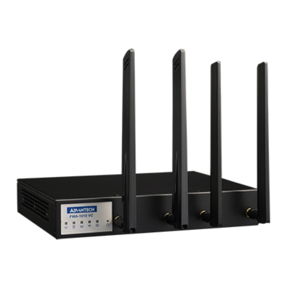
FWA-1010VC Network system with Intel®
Atom® C2000 Processor Platform
Packing List
Before you begin installing your card, please make
sure that the following items have been shipped:
• One FWA-1010VC System
• One space of accessories
• One warranty certificate
If any of these items are missing or damaged, please
contact your distributor or sales representative
immediately.
Note 1: Acrobat Reader is required to view any PDF
file.Acrobat Reader can be downloaded at:
www.adobe.com/Products/acrobat/readstep2.
html (Acrobat is a trademark of Adobe)
For more information on this and other
Advantech products, please visit our website at:
http://www.advantech.com.tw/support
http://www.advantech.com
For technical support and service, please visit
our support website at:
http://www.advantech.com/support
This manual is for the CGS6000 series Rev. A
Part No. TBA
Print in China
Draft Edition,
Specifications
Main Board Functions
• CPU:
Dual Intel® C2000, L2 Catch: 2MB/4MB (by CPU SKU)
• Memory:
Supports two DDR3/DDR3L Memory DIMMs
up to 1600 MHz, depending on CPU SKU
• Storage:
Up to 1 x 2.5" SSD bracket(by product sku),
1x M.2 2280 SSD slot
• Dimensions:
250 x 44 x 190.4mm (W x H x D)
• Power Supply:
60W, 100 V ~ 240 V @ 50 ~ 60 Hz, full range
Advertisement
Table of Contents

Related Manuals for Advantech FWA-1010VC


Summary of Contents for Advantech FWA-1010VC
-
Page 1: Specifications
(Acrobat is a trademark of Adobe) 60W, 100 V ~ 240 V @ 50 ~ 60 Hz, full range For more information on this and other Advantech products, please visit our website at: http://www.advantech.com.tw/support http://www.advantech.com For technical support and service, please visit our support website at: http://www.advantech.com/support... - Page 2 1. HARDWARE INSTALLATION INTRODUCTION 1.1 MEMORY INSTALLATION 1.1.1 Open the top cover and insert DDR3 UDIMM module into the socket, insert RAM module into black socket first then insert RAM module in orange socket...
- Page 3 1.2 2.5” SSD BRACKET INSTALLATION=> 1.2.1 Get 4 pcs M3*4.0L screws & SSD bracket from accessory box M3*4.0L screw...
- Page 4 1.2.2 Use screwdriver locking 4 screws to fix 2.5” SSD in SSD bracket. 1.2.3 Get 4 pcs M3*4L screws from accessory box M3*4 screw...
- Page 5 1.2.4 Use screwdriver locking 4 screws to fix SSD bracket on FWA-1010VC, SSD SATA & power connector side needs face from chassis side. 1.2.5 Please connect SATA & Power cable to SSD connectors.
-
Page 6: Ssd Installation
1.3 M.2 SSD INSTALLATION 1.3.1 Get M.2 module & Screw M3*3.5 (P/N: 1930006888-01) 1.3.2 Use screwdriver locking a screw to fix M.2 module and FWA-1010VC M/B. -
Page 7: Wallmount Kit Installation
1.5 RackMount Kit Installation Get 6 pcs M3*4L screws from accessory box Plug in Power Adaptor into power Adaptor bracket Revert power adaptor bracket into rack-mounting bracket Please use screwdriver locking 6 screws to fix RackMount Kit bracket on FWA-1010VC... - Page 9 2. BIOS CONSOLE REDIRECTION SETTING 2.1 CONSOLE REDIRECTION FUNCTION INSTALL &SETTING 2.1.1 FWA-1010VC doesn’t have a VGA function; user needs to use console-redirection cable(please contact your Advantech contact window to order this cable) to control FWA-1010VC function, 2.1.2 Please use RJ45 to console cable to connect FWA-1010VC’s Console port and Test PC’s RS232 COM port, user may press “DEL”...
- Page 10 2.1.3 Choose “Advanced” “Serial Port Console Redirection” item. 2.1.4 Default console redirection setting of FWA-1010VC BIOS is COM1...
- Page 11 2.1.5 Baud rate setting is 115200,8,n1, and “Redirection after BIOS POST” is Always.
- Page 12 SETTING Advantech provided FWA-1010VC Quick Start Linux image which is based on Ubuntu Linux distribution and is configured to run on FWA-1010VC for vE-CPE and SD-WAN applications. Useful software utilities and tools which are either Advantech proprietary or are under opens source license are integrated into the image to provide customers with a quick and easy approach for platform evaluation.
- Page 13 4. FWA-1010VC BIOS FLASH STEP 4.1 FWA--1010VC BIOS flash step. FWA-1010VC BIOS V016 or latest version are support flash BIOS by UEFI shell, when user needs flash er below step to flash FWA-1010VC BIOS. 4.1.1 Please copy BIOS & flash tool (ex: fpt.efi) in USB flash, and insert USB flash to FWA-1010VC.
- Page 14 4.1.3 Please press “ESC” to skip startup.nsh, it will show “Shell >” message 4.1.4 When system only install a USB flash, EFI shell will detect USB flash as “fs0”, if system install 2 USB flash , EFI shell will detect USB flash as “fs0” and “fs1”.
- Page 15 4.1.7 Kindly key-in “fpt.efi 0f “BIOS file” to flash FWA-1010VC BIOS, and please don’t power off system during the flash BIOS. 4.1.8 When BIOS flash finish. Please power off and re-power on system, the system BIOS will flash to new version.
- Page 16 SYSTEM PLATFORM SKUS FWA-1010VC-4CA2S: Tabletop 1x 60W Power Adaptor, CPU 4Core C2558 1x M.2 2280 SSD slot, 7x 1GbE Ethernet port, 2x 1GbE SFP port and 4x 1GbE switched Ethernet port with 1GbE uplink to CPU FWA-1010VC-8CA2S: ...
-
Page 17: System Architecture
5.1 System Architecture FWA-1010VC System Architecture... - Page 18 5.1.1 Front Side FWA-1010VC System Front View 5.1.2 Rear Side FWA-1010VC System Rear View...
-
Page 19: System Block Diagram
5.2 System Block Diagram FWA-1010VC System Block Diagram... - Page 20 6. NAMB-1010VCMB JUMPER SETTING AND CONNECTOR LIST 6.1 Connector NAMB-1010VCMB Top side Connector Placement...
- Page 21 NAMB-1010VCMB Bot side Connector Placement Location Description Comment DC POWER JACK 4P 90D(M) DIP DC_JACK1 DC12V Power Input. 2DC-0006-B01 CN75 USB Conn 4P 90D(F) DIP USB-1F0401-2W For USB Function. PHONE JACK RJ45 8P 1.02mm 90D(F) DIP CN41 For Console. C20GY0-500 PHONE JACK RJ45 28P 2.54mm 90D(F) DIP For 2x1 LAN w/ Combo CN76...
- Page 22 Location Description Comment WAFER BOX 2P 3.96mm 180D(M) DIP CN44 For Power Switch Cable. 3961-WS-2-LF WAFER 2.54 1*4P 180D(M) DIP FAN1 For system cooler use. 744-81-04TW30 SPI1 IC SKT 8P SMD 8P SMD ACA-SPI-004-K01 For CPU BIOS EEPROM. WAFER BOX 2x5P 2.00mm 180D(M) DIP CN40 For TPM and LPC function.
-
Page 23: Jumper Setting
6.2 Jumper Setting Clear CMOS Header (JP1) Use a three pin header. For Clear CMOS data Clear CMOS Jumper Definition Pitch: 2.00mm Jumper Circuit Comme 1-2 Installed Pull up Pull up to +VBAT 3.3V, Normal status (Default) 2-3 Installed Pull down Pull to ground to clear CMOS JP1 Symbol (NAMB-1010VCMB) -
Page 24: Lpc Connector
SATA Power CONNECTOR SATA Power Connector (CN45) CN45 Symbol (NAMB-1010VCMB) DC12V Power CONNECTOR Power Switch Connector(CN44) CN44 Symbol (NAMB-1010VCMB) LPC CONNECTOR Connector(CN40) CN40 Symbol (NAMB-1010VCMB)
Need help?
Do you have a question about the FWA-1010VC and is the answer not in the manual?
Questions and answers