Table of Contents
Advertisement
Quick Links
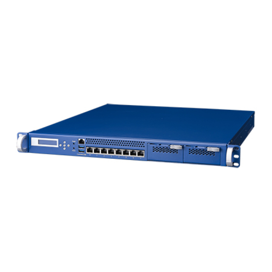
FWA-3232 1RU Network Application Platform X86-Based Intel®
Xeon
series and 4
TM
Startup manual
Packing List
Before installation, ensure that the following materials
havebeen received:
One FWA-3232 Internet Security Platform
One box of accessories
One warranty certificate
If any of these items are missing or damaged, please
contactyour distributor or sales representative immediately.
Note:
Acrobat Reader is required to view any PDF file.
Acrobat Reader can be downloaded at:
www.adobe.com/Products/acrobat/readstep2. html
(Acrobat is a trademark of Adobe)
generation Core
th
i7/i5/i3 processor
TM
Specification
Main Board Functions
TM
CPU: Intel® Xeon
E3-1275/E3-1225/E3-1268LV3, 4th
TM
Gen Intel® Core
Processors i7-4790S, i7-4770S,
i7-4770TE, i5-4590S,i5-4570S,i5-4590T,i5-4570TE,
i3-4360,i3-4330, i3-4350T,i3-4340TE,i3-4330TE, Intel®
Pentium® Processor G3420,G3320TE and Intel® Celeron®
Processor G1820, G1820TE(LGA1150)
Chipset: Intel® C226/H81 PCH
Memory: Dual channel DDR3 1333/1066 MHz ECC(Xeon®
processors only) Un-buffered memory, up to 32GB
PCI-Express:1xPCIe x8 gen.3,1xPCIe x4 gen.2 for FH/HL
PCI-e cards
Network Connectivity:
NMC : up to 2x NMC Modules with PCI-e x8 gen.3
interfaces
Ethernet : 8 or 6 x Intel I210-AT 10/100/1000 Mbps
Ethernet
Mass Storage: 2 x 2.5" internal ,1 x 3.5" SATA HDD/SSD,
speed up to 6Gb/s, 1x Half/Full Size mSATA module, speed
up to 6GB/S
Peripherals:
LCD Module:32x128 graphic display,5 buttons
Console:1 x RJ45 Console port
USB:2 x USB2.0 Type A connector
TPM: TPM1.2(Infineon_SLB9635TT)
Power supply:300W, AC/DC redundant ,300W/250w AC
Single power
Dimensions(W x H x D): 430 x 44 x 500 mm/ 430 x 44 x 375
mm
Weight:10KG/6KG
Environment: Operating
Temperature: 0 ~ 40℃
(32 ~ 104° F)
Humidity: 5 ~ 85% @ 40℃
Non-operating
-40 ~ 60℃
(-40 ~ 140° F)
5 ~ 95% @ 40℃(104℉)
Advertisement
Table of Contents

Related Manuals for Advantech FWA-3232


Summary of Contents for Advantech FWA-3232
- Page 1 FWA-3232 1RU Network Application Platform X86-Based Intel® Xeon series and 4 generation Core i7/i5/i3 processor Startup manual Packing List Specification Before installation, ensure that the following materials Main Board Functions havebeen received: CPU: Intel® Xeon E3-1275/E3-1225/E3-1268LV3, 4th One FWA-3232 Internet Security Platform Gen Intel®...
-
Page 2: Specification
Specification Express Modules Support Advantech NMCs as the form shows: Interface: one LCM with 5 buttons, 1 console port, 2 LAN Ethernet NMCs Interface Controller RJ45 connectors, 1 USB connectors and one power button. Intel NMC-0107 4 GbE LAN... -
Page 3: Installation
Installation Installing the CPU Installing the heatsink and air scoop 1. Take out the heatsink, air scoop,2pcs of silvery screws and 1. Locate the CPU sockets on the board 4pcs of black screws;Place the heatsink into air scoop and lock them with the 4pcs black screw as the picture shows. - Page 4 Installation Installing the the Riser Cards Installing the 3.5’ HDD 1. Remove the screws and HDD bracket signed by the arrows. Take out the HDD rubbers and screws 6pcs each from the 移除下图一箭头位置之机箱背面的两颗螺丝, accessory box ; 2. Fix the rubbers on the HDD bracket as picture shows; 2.
- Page 5 connect it as the picture shows; Then connect the SATA power cable to HDD interface.
-
Page 6: Installing The 2.5' Hdd
Installation Installing Express Modules Installing the 2.5’ HDD 1.Release the 2 screws. Push the lower half of the baffle and 1.Take out the HDD rubbers and screws from the accessory take it out; box ,and push the rubbers into the hole on the bracket; 2.Insert the express module into the case and tighten the screws. -
Page 7: Jumper And Connectors
Installation Jumper and Connectors Connection for DC power source The board has a number of jumpers that allow you to configure your system to suit your application. The table below lists the Attention: Only trained service personnel are authorized to install and function of each of the jumpers and connectors. - Page 8 Jumper and Connectors JCMOS1 ATXPWR1 Pins Function Pins Function 3.3V Normal status 3.3V Clear CMOS Default setting:1-2 Jumper Short 5VSB JUART1_SW1 Pins Function UART1 SWITCHED BY COM_SOL_CTRL 3.3V WHEN BMC LOADED, BMC_DETECT# CHANGE 3.3V TO 0, UART1 SWITCHED TO SOL -12V Default setting:1-2 Jumper Short PSON...
- Page 9 Jumper and Connectors LAD3 USB3_4 +V3.3 Pins Function Data9- Data8- Data9+ Data8+ SYSFAN1~SYSFAN4 Pins Function Power FANIN LPC1 VGA1 Pins Function Pins Function LPC_FRAME# LAD0 4,9,11,13,15 LAD1 SERIRQ LAD2 DDAT RESET#...
- Page 10 VCC3 JTAG_TMS DCLK GND_V JTAG_TDI JTAG_TDO JTAG_RST# JTAG1 Pins Function JTAG_TCK...
- Page 11 Jumper and Connectors KBMS1 Pins Function MSCK +V5_SB MSDT KBDT KBCK GPIO1 Pins Function GPIO0 GPIO4 GPIO1 GPIO5 GPIO2 GPIO6 GPIO3 GPIO7...
-
Page 12: Software Installation
Software Installation 、 Software List: Windows Server2008 R2 64bit Windows 7 Ultimate English 32 bit Red Hat Enterprise 6.1 32bit/64bit... -
Page 13: Board Placement
Board Placement... -
Page 14: Safety Instructions
Safety Instructions 1. Read these safety instructions carefully. 2. Keep this user manual for later reference. 3. Disconnect this equipment from AC outlet before cleaning. Do not use liquid or spray detergents for cleaning. 4. For pluggable equipment, the power outlet shall be installed near the equipment and shall be easily accessible. 5. - Page 15 19. CAUTION: Always ground yourself to remove any static charge before touching the motherboard, backplane, or add-on cards. Modern electronic devices are very sensitive to static electric charges. As a safety precaution, use a grounding wrist strap at all times. Place all electronic components on a static-dissipative surface or in a static-shielded bag when they are not in the chassis. 20.
- Page 16 21. “Rack Mount Instructions - The following or similar rack-mount instructions are included with the installation instructions: A) Elevated Operating Ambient - If installed in a closed or multi-unit rack assembly, the operating ambient temperature of the rack environment may be greater than room ambient. Therefore, consideration should be given to installing the equipment in an environment compatible with the maximum ambient temperature (Tma) specified by the manufacturer.
Need help?
Do you have a question about the FWA-3232 and is the answer not in the manual?
Questions and answers