
Related Manuals for Advantech FWA-2320


Summary of Contents for Advantech FWA-2320
- Page 1 User Manual FWA-2320 1U Entry-level Network Appliance Based on Intel® Atom™ C2000 System On Chip...
- Page 2 No part of this manual may be reproduced, copied, translated or transmitted in any form or by any means without the prior written permission of Advantech Co., Ltd. Information provided in this manual is intended to be accurate and reliable. How- ever, Advantech Co., Ltd.
- Page 3 This publication is a useful reference when installing, configuring, operating and managing the FWA-2320. This manual is organized as follows: Section 1: Getting Started helps you with the first steps with the FWA-2320. Section 2: Product Specification provides a detailed description of the FWA- 2320 and its features.
- Page 4 Please let us know of any aspect of this product, including the manual, which could use improvement or correction. We appreciate your valuable input in helping make our products and documentation better. Please send all such - in writing to: ncg@advantech.com Glossary ACPI...
- Page 5 SCSI Small Computer System Interface Sensor Data Record SerDes Serializer/Deserializer Serial Over LAN Solid State Disk Software Trusted Platform Module Transmit UDIMM Unbuffered DIMM UHCI Universal Host Controller Interface Universal Serial Bus FWA-2320 User Manual...
- Page 6 FWA-2320 User Manual...
-
Page 7: Table Of Contents
Figure 2.7 ATOM C2000 SKUs for Communications Infrastructure 2.4.4 Memory ..................22 Figure 2.8 DIMM Location ............22 Table 2.8: DIMM Mapping ............22 Table 2.9: Validated DIMMs ............22 2.4.5 Chipset..................23 Table 2.10: USB Ports..............23 Figure 2.9 USB DOM..............23 FWA-2320 User Manual... - Page 8 Figure 3.7 Advanced Setup: PCI Subsystem ......45 Table 3.3: Advanced Setup: PCI Subsystem Menu Items ..46 Figure 3.8 Advanced Setup: Network Stack Configuration Menu . Table 3.4: Network Stack Configuration Menu......47 Figure 3.9 Advanced Setup: CSM Configuration Menu..... 47 FWA-2320 User Manual viii...
- Page 9 Figure 3.43DIMM insertion into slide rails........70 Figure 3.44Seating the DIMM in the socket........ 71 Firmware Upgrades................. 71 3.4.1 BIOS ................... 71 3.4.2 LAN Bypass ................72 Replacing FRUs ..................72 3.5.1 Disk Drives.................. 72 3.5.2 CMOS Battery................73 FWA-2320 User Manual...
- Page 10 ......79 BIOS Post Codes..................80 Appendix C Declaration of Conformity....85 Declaration of Conformity ............... 86 C.1.1 CE....................86 C.1.2 FCC Class A ................86 Appendix D Warranty and RMA......87 Warranty and RMA ................. 88 FWA-2320 User Manual...
-
Page 11: Chapter 1 Getting Started
Chapter Getting Started... -
Page 12: Safety Instructions
Advantech intends to provide all necessary information to install and handle the FWA-2320 in this manual. Because of the complexity of this product and its various uses, we do not guarantee that the given information is complete. If you need addi- tional information, contact your Advantech representative. -
Page 13: Safety Precautions - Static Electricity
Table 1 is missing or damaged, please contact your Advantech representative. When opening the box, you will find the FWA-2320 embedded in protective foam and the accessory box embedded to the foam. Remove the accessory box first and then pull out the unit including the protective foam using both hands. - Page 14 USB DOM Screw for USB DOM mount- screw SATA Cable for HDD con- SATA Cable nection Mounting Ears for Rack- Mounting Ears 2 mounting Screws (6pcs) for mounting Mounting Ear the ears on the chassis Screw Set FWA-2320 User Manual...
-
Page 15: Installation And Configuration
The FWA-2320 comes as a pre-configured system with CPUs, memory and peripher- als installed in the unit. In the rare case that you procured a barebone system or need to install components in the FWA-2320 for any other reason, please refer to section 1.3.1 Rack Mounting The FWA-2320 appliance is designed to be installed in a standard 19-inch rack. -
Page 16: Powering On
Before connecting the FWA-2320 to the power outlet, please make sure that the power rating of the outlet and the FWA-2320's PSU match. Please also make sure that the primary circuit and all power distribution in not overloaded. Inrush current and steady state power specifications for the FWA-2320 can be found in appendix C as well as the type label on the bottom of the unit. - Page 17 Figure 1.3 PuTTY Session Configuration Figure 1.4 PuTTY Serial Configuration FWA-2320 User Manual...
- Page 18 Figure 1.5 PuTTY Keyboard Settings Figure 1.6 PuTTY Colour Settings FWA-2320 User Manual...
-
Page 19: Installing An Os
Install an image from a USB key Install an OS via network boot. If you use Advantech’s services to pre-install an OS, you can skip the following sec- tion. 1.3.4.1 Pre-Installed reference OS If you receive this manual along with a sample unit, the system will have a reference OS installed by default. - Page 20 PuTTY as described earlier. Power on the appliance. The boot priority in the FWA-2320’s BIOS is giving SATA devices higher priority than USB devices. This is a safety measure to avoid that any end user can tam- per the unit when installed in the field with a bootable USB stick.
- Page 21 It needs to set BIOS/ Advanced-> Network Stack Configuration-> Network Stack as enabled (default setting is disabled) When set Network Stack is enabled, it may set IPV4 PXE & IPV6 PXE function as enabled/disabled, and set PXE boot wait time (range 0~5) & Media detect time(range 0~50). FWA-2320 User Manual...
- Page 22 Save BIOS and reboot system. The BIOS will show “Checking Media Pres- ence..”, if system is not connected PXE server, it will show “No Media Pres- ent..” FWA-2320 User Manual...
- Page 23 DHCP required for PXE booting may conflict with existing DHCP serv- ers in your network. The PXE client in the FWA-2320 sends the system’s GUID as part of the DHCP Request. Some boot servers have mechanisms to automatically configure the target OS image based on the client system’s GUID.
-
Page 24: Getting Help: Technical Support And Assistance
In case the unit you received is a sample for evaluation, please contact your Advan- tech representative. For production units, please follow the process below: Visit the Advantech web site at www.advantech.com/support to find the latest information about the FWA-2320 and related products. -
Page 25: Chapter 2 Product Specification
Chapter Product Specification... -
Page 26: Overview
Intel? Atom? processor C2000 family extending the scalability of the Intel? platform for communications infrastructure from high end ATCA based systems all the way down to this entry level 1U rackmount appliance. The FWA-2320 can sup- port 2-core, 4-core and 8-core processor SKUs with or without QuickAssist hardware acceleration providing additional flexibility to Network Equipment Providers to choose a platform which meets their performance / price targets. -
Page 27: Product Versions
Table 2.1: System Components PCIe expansion card mounting area Rear fan Product Versions The FWA-2320 is available in the following standard configurations. Contact your Advantech representative for availability of other configuration options. Table 2.2: Available Product Versions Model Name Configurations C2358 (2C/ 1.7GHz) with 2Gbps QuickAssist... -
Page 28: System Dimensions
Figure 2.2 System Dimensions 2.3.2 Regulatory Compliance The Advantech FWA-2320 meets the specifications and regulations for safety and EMC defined in this chapter. Please contact your Advantech representative for a copy of the declaration of conformity or detailed test reports. -
Page 29: Detailed Description
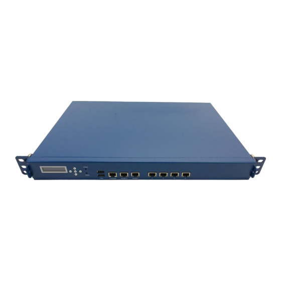
USB Connector Stacked Type A USB connector providing 2 USB2.0 ports Console Connector RS232 Console Connector Management Port 0 Management LAN Port 0 Management Port 1 Management LAN Port 1 Traffic Port 1 Traffic LAN Port 1 FWA-2320 User Manual... -
Page 30: Rear Elements
LED is amber and indicates hard disk and mSATA activity. 2.4.2 Rear Elements Figure 2.5 System Rear View Table 2.7: Rear elements Item Element Description System fan Rear system fan exhaust Power inlet Power connector Power Supply fan Exhaust of PSU fan On/Off Switch Power Switch FWA-2320 User Manual... -
Page 31: System Block Diagram
Figure 2.6 Block diagram 2.4.3.1 Processor(s) The FWA-2320 supports one ATOM C2000 processor. The table below gives an overview of the processor SKUs for communication infrastructure which can be sup- ported on the FWA-2320: Figure 2.7 ATOM C2000 SKUs for Communications Infrastructure Please note that the ATOM C2000 is soldered on the motherboard and cannot be installed later. -
Page 32: Memory
For details on the features of the Atom C2000 processor, please refer to documenta- tion available from intel. 2.4.4 Memory Two DDR3L or DDR3 DIMMs are supported on the FWA-2320. Both DIMMs reside on the CPU’s memory channel A and can support operation up 1600MT/s (CPU SKU dependent). Figure 2.8 DIMM Location Table 2.8: DIMM Mapping... -
Page 33: Chipset
The chipset / PCH functionality is integrated into the Atom C2000 SoC. 2.4.5.1 The FWA-2320 supports six two external USB2.0 ports which can be used to connect low, full and high speed devices. The 5V supply rail supplied to external devices is current limited by a self resetting, electronic fuse to 500 mA. - Page 34 Hub to support USB 1.1 devices. Universal Host Controller and Open Host Con- troller Interfaces are not supported by the Atom C2000 device. Please note that the BIOS of the FWA-2320 supports disabling the USB Controller as well as specific USB device classes. Please refer to chapter BIOS / BIOS Setup Menu for details.
- Page 35 The following list summarizes the drives validated on the FWA-2320: Table 2.13: Validated SATA Drives Vendor Vendor PN (Capacity) Advantech PN HDD Drive WD5000AAKX 500GB 3.5” SATA HDD 96HD500G-ST-WD7K2 Seagate ST3000DM001 3.5”3TB SATA HDD 96HD3T-ST-SG7K Seagate ST3000VX000 3.5" 3TB SATA HDD 96HD3T-ST-SG7KE WD10EZEX 3.5”...
- Page 36 IO Range 0x3f8 -0x3ff, IRQ4 Console port COM2 IO Range 0x2f7 – 0x2ff, IRQ3 Interface to LCM Please note that the UARTs in the SoC do not support any UART handshake and sta- tus/control signals but RXD, TXD, only. FWA-2320 User Manual...
- Page 37 Timers) Specification, Revision 1.0 available from intel. SMBus The PCH integrates two SMBus controllers. The first one is used as interface to external devices such as EEPROMs, the hardware monitor; the second controller is not used on the FWA-2320. Table 2.15: SMBus Devices SMBus Adr,...
-
Page 38: Network Interfaces (Onboard)
C2000 SoC and referenced as “i354”, a derivative of the popular i350 standalone controller. Marvell 88E1111 PHYs are provided on the FWA-2320 to support 10/100/1000 Base- T. These PHYs will be detected and configured automatically by the standard Ether- net drivers available from Intel. -
Page 39: Mass Storage
2.4.10 Mass Storage Up to three SATA devices and a USB DOM are supported by the FWA-2320. In the default configuration, two SATA devices are supported: an onboard mSATA socket (location M3) and a 3.5" HDD site (M7). The USB DOM socket can be found at M6. - Page 40 2.4.11.2 BIOS Defaults The BIOS comes with a set of configuration parameters when shipped by Advantech referred to as “Optimized Defaults” or “factory defaults”. The user can change BIOS settings via the setup menu either temporarily or permanently by saving the changes as “User defaults”.
-
Page 41: Platform Management
Platform Management A Nuvoton NCT7904 Hardware Monitor Chip (HWM) provides hardware monitoring capabilities on the FWA-2320. The HWM chip is connector to the PCH’s SMBus. Standard software packages such as “lmsensors” can be used on the host to provide sensor information under Linux. Advantech provides the required patch that adds support for the HWM chip and a system specific configuration file. -
Page 42: Thermal Management
C5. The PSU has an integrated fan which also pulls air into the PSU via the openings at C2 and exhausts air at the rear opening of the PSU module (C6). For cooling PCIe expansion cards, there are additional vent holes in area C3. FWA-2320 User Manual... -
Page 43: Power Supplies
2.4.14.1 Product Labelling The FWA-2320 contains a number of labels that help to identify the product as well as the MAC addresses used by the system. The type label is placed on the bottom side of the unit and other labels can be found inside the unit. - Page 44 Type Label 2.4.14.2 Electronic Label: FRU EEPROM The FWA-2320 supports an onboard FRU EEPROM which can be accessed via SMBus 0 using afru. The table below shows the FRU EEPROM format: < add here> Alternatively, FRU information is also embedded in DMI Tables 1/2/3 and can be dis- played with DMI parsing tools like dmidecode.
-
Page 45: Advanced Platform Features
2.5.1 Intrusion Detection The FWA-2320 does not support intrusion detection by default. This feature has been reserved in the motherboard design, though, and can be enabled at system level via customization. Please contact your Advantech representative should you be inter- ested in this option. - Page 46 2.5.3.3 LED Behaviour Advantech Advanced LAN bypass uses a LED to show the state of a bypass seg- ment. Usually the bypass LED is implemented as a dual colour LED combined with a regular LAN port LED. The table below shows the status of the bypass LED, only. For a complete description of port LEDs please refer to Appendix A.3.2).
-
Page 47: Available Accessories And Related Products
Available Accessories and Related Products 2.6.1 Accessories The following accessories are available for ordering. Please contact your Advantech representative for a list of available and supported peripherals such as memory mod- ules, hard disks and solid state drives. Table 2.20: Accessories... - Page 48 FWA-2320 User Manual...
-
Page 49: Configuration And Service
Chapter Configuration and Service... -
Page 50: Jumper Settings
BIOS Setup Menu This section describes the FWA-2320’s UEFI BIOS based on AMI’s APTIO BIOS. Users can modify BIOS settings and control the special features of the FWA-2320 using the BIOS setup menu. Please note that Advantech supports shipping the FWA-2320 with custom BIOS defaults to simplify the deployment and integration for our customers. -
Page 51: Main Setup Menu
Figure 3.3 BIOS Setup Main screen The main setup page displays system a summary of system and BIOS configuration and status information. The fields on this page are read-only except for the System Date and Time setting. FWA-2320 User Manual... -
Page 52: Advanced Setup Menu
3.2.2 Advanced Setup Menu Select the Advanced tab from the FWA-2320 setup screen to enter the Advanced BIOS Setup screen. Users can select any of the items in the left frame of the screen, such as the Trusted Computing Configuration, to go to the sub menu for that item. - Page 53 The settings for COM1 console can be accessed in this menu. is sub menu allows you to change the settings used for the serial console. For exam- ple, users can define the terminal type, bits per second, data bits, parity, stop bits and others. FWA-2320 User Manual...
- Page 54 When using Legacy OS, this item specifies the Num- rection 80x 25 ber of Rows and Columns supported VT100 /. LINUX / Select Function Key and Key Pad Emulation on PuTTY Keypad XTERMR6 / SCO PuTTY. / ESCN / VT400 FWA-2320 User Manual...
- Page 55 This menu contains settings for the PCIe subsystem. Some menu items are referred to as “PCI” settings. Although the FWA-2320 does not implement a PCI bus, these settings still apply to the platform as PCIe is using the same configuration mecha- nism as PCI.
- Page 56 Address Space. PCI Express Set- none Submenu Change PCI Express Devices Settings. tings 3.2.2.4 Network Stack Configuration This menu configures the built in network stack of the BIOS. Figure 3.8 Advanced Setup: Network Stack Configuration Menu FWA-2320 User Manual...
- Page 57 Timeout in seconds to detect network 0-50 Time media 3.2.2.5 Compatibility Support Module (CSM) Configuration This submenu allows users to configure the support for legacy BIOS mechanisms and option ROMs. Figure 3.9 Advanced Setup: CSM Configuration Menu FWA-2320 User Manual...
- Page 58 UEFI compliant Option UEFI Only ROMs Network Storage This item allows a more granular control Option ROM Do not launch of OptionROM execution depending of Video execution UEFI Legacy the type of extension device. Other PCI device FWA-2320 User Manual...
- Page 59 Is displayed when TPM support is dis- Display Only abled Current Sta- TPM State Display Only Shows TPM Enablement Status tus informa- tion TPM Active State Display Only Shows TPM Activation Status TPM Owner Display Only Shows Current TPM Owner FWA-2320 User Manual...
- Page 60 10sec / 20sec / Time Out for a device to Reset USB Timing time-out 30sec / 40sec Maximum time the device will take Device power-up Auto before it properly reports itself to the delay Manual Host Controller. FWA-2320 User Manual...
- Page 61 However, those terms are kept consistent with previous products to allow users to navigate more eas- ily. The sub menus are described on the following pages. Figure 3.12 Chipset Configuration Menu FWA-2320 User Manual...
- Page 62 Figure 3.13 Chipset: Processor Configuration Menu Table 3.8: Processor Configuration Menu Access / Group Setup item Description Options Processor ID Processor Fre- quency Processor Displays information on the processor L1 Cache RAM Display only Configuration installed L2 Cache RAM Processor Ver- sion FWA-2320 User Manual...
- Page 63 Enable dual core processor SKUs) Disable Enables or Disables the CPU’s Running RAPL Enable Average Power Limit Capability (RAPL). Active Processor Number of cores enabled in the CPU Core (This item is hidden on 2 core SKUs) FWA-2320 User Manual...
- Page 64 This menus supports configuration of the platform clock generator. Figure 3.14 CK420 Configuration Menu Table 3.9: CK420 Configuration Menu Access / Group Setup item Description Options CK420 Spread Enabled Enables Spread Spectrum Operation for Spectrum Disabled lower EMI. FWA-2320 User Manual...
- Page 65 3.2.3.3 Chipset Setup: North Bridge Configuration This menu allows the configuration of the memory controller and related features of the SoC. Figure 3.15 NorthBridge Configuration Menu FWA-2320 User Manual...
- Page 66 Select the patrol scrub Period Period 4 hours 1 hour Select to enable / disable Demand Demand Scrub Scrub Support Enabled Enable For more information on demand scrub, please refer to section Scrambler Enabled Select to enable / disable the Scrambler FWA-2320 User Manual...
- Page 67 3.2.3.4 Chipset Setup: South Bridge Configuration Figure 3.16 South Bridge Configuration Table 3.11: South Bridge Configuration Feature Default Description SMBus Controller Enabled Enabled/Disabled SMBus Controller. South Bridge Configuration: SATA Configuration Figure 3.17 SATA Configuration FWA-2320 User Manual...
- Page 68 If ONLY the User's password is set, then this is a power on pass- word and must be entered to boot or enter Setup. In Setup the User will have Administrator rights. The password length must be in the following range: – Minimum length: 3 – Maximum length: 20 FWA-2320 User Manual...
- Page 69 Disabled of a minimal set of devices required to launch active boot option. Boot Option User Defined Sets the system boot order. Set the order of the legacy devices in this Hard Drive BBS Priorities Submenu group. FWA-2320 User Manual...
- Page 70 3.2.6 Save & Exit Menu The FWA-2320 BIOS allows users to store BIOS configuration results as “User Defaults.” Users can select “Save as User Defaults” to record all changes which had been made in previous pages as the default setting for further use.
- Page 71 After that, slide the top cover backwards until the front flange of the top cover disen- gages with the unit's face plate: Figure 3.22 SlideTop Cover back FWA-2320 User Manual...
- Page 72 You need: a PH2 screw driver a standard 2.5” SATA HDD the HDD screw kit (included in the unit) the HDD carrier plate the SATA cable Figure 3.24 Screws for HDD mounting FWA-2320 User Manual...
- Page 73 2 holes on each side of the carrier plate. The holes to use may vary from disk vendor to disk vendor. For some vendors, all 4 holes may align. Figure 3.25 HDD Carrier plate dampeners Figure 3.26 Carrier plate and HDD alignment FWA-2320 User Manual...
- Page 74 Figure 3.27 Screw insertion and fastening Move the carrier plate into the system location M7 and align the carrier plate’s mounting holes with the standoffs in the chassis. Figure 3.28 HDD Carrier plate screw locations FWA-2320 User Manual...
- Page 75 Insert the carrier plate mounting screws and start to fix them from the front side (i.e. the side facing the FWA-2320 motherboard). Securely tighten the screws using a PH2 screw driver after having inserted all four screws. Figure 3.29 Insertion of the carrier into the chassis Connect the SATA cable delivered with the unit to the disk as well as the mother board connector.
- Page 76 Figure 3.32 HDD Power cable 3.3.3.2 USB DOM You need: a PH2 screw driver a standard USB DOM the USB DOM mounting screw (included in the unit) Figure 3.33 USB DOM mounting screw FWA-2320 User Manual...
- Page 77 Figure 3.35 USB DOM alignment If properly inserted. The mount hole in the DOM and the threaded insert will be aligned. Insert the DOM mounting screw and tighten it. Figure 3.36 USB DOM mounting FWA-2320 User Manual...
- Page 78 Figure 3.38 mSATA key alignment Insert the mSATA module in the connector under an angle of around 45°. The gold contacts of the module will almost disappear in the connector when the module is fully seated. Figure 3.39 mSATA angled insertion FWA-2320 User Manual...
- Page 79 Push down the module softly until it is in horizontal position. If the module is cor- rectly seated, the module’s right hand mount hole will align with the threaded standoff in the FWA-2320 motherboard. Insert the mSATA mounting screw and tighten it.
- Page 80 Insert the DIMM from the top using the guide rails on the left and right of the DIMM sockets. Figure 3.43 DIMM insertion into slide rails Put your thumbs near the right and left end of the DIMM and press down the DIMM evenly until the white latches fully close with a click. FWA-2320 User Manual...
- Page 81 Linux distributions. Documentation on flashrom can also be found there. Start flashrom with the following parameters to update the BIOS on the FWA-2320: -w (BIOS Name) –p internal: laptop=this _is _not_laptop...
- Page 82 Remove the USB DOM mounting screw.. Extract the USB DOM by pulling the DOM upwards evenly. Be sure not to bend any USB DOM connector pins. Install a new SSD following the mounting instructions of the same section. FWA-2320 User Manual...
- Page 83 Please make sure you insert the battery in correct polarity with the positive pole fac- ing the front panel and the negative pole facing the CPU heatsink. Trying to insert the battery with incorrect orientation/polarity will damage the battery holder. Additional security risks apply as stated above. FWA-2320 User Manual...
-
Page 84: Dimms
As the latches flip completely open, the DIMM module will be automatically extracted from the socket. Pull the DIMM module out vertically. Figure 3.47 Unlocking and removing a DIMM To insert a new DIMM please follow the process described in section 3.3.3. FWA-2320 User Manual... -
Page 85: Connector Pinout And Led
Appendix Connector Pinout and LED Information... -
Page 86: Console Port (Rs232)
Not connected n.c. Not connected Transmit Data (Output from FWA-2320) Digital Circuit Ground Digital Circuit Ground Receive Data (input to FWA-2320) n.c. Not connected n.c. Not connected USB Type A Connectors These connectors can be found at position F4 Figure A.2 Stacked USB Type A connector Table A.2: Stacked USB Type A Connector Pin Assignment... -
Page 87: Rj45 10/100/1000 Base-T Ports
Bypass Status: 1000 Mbps Static Green Blinking Amber Disconnect Bypass Status: Static Amber Bypass Note! Bypass States are only signalled on the traffic LAN ports. Management LAN ports do not have this extra LED colour & signalling. FWA-2320 User Manual... - Page 88 FWA-2320 User Manual...
-
Page 89: Appendix Bbios Post Codes
Appendix BIOS Post Codes... -
Page 90: Bios Post Codes
CPU post-memory initialization is started 0x33 CPU post-memory initialization. Cache initialization CPU post-memory initialization. Application Processor(s) (AP) initializa- 0x34 tion 0x35 CPU post-memory initialization. Boot Strap Processor (BSP) selection CPU post-memory initialization. System Management Mode (SMM) ini- 0x36 tialization FWA-2320 User Manual... - Page 91 South Bridge DXE Initialization (South Bridge module specific) 0x73 South Bridge DXE Initialization (South Bridge module specific) 0x74 South Bridge DXE Initialization (South Bridge module specific) 0x75 South Bridge DXE Initialization (South Bridge module specific) 0x76 South Bridge DXE Initialization (South Bridge module specific) FWA-2320 User Manual...
- Page 92 Configuration Reset (reset of NVRAM settings) 0xC0 – 0xCF unused 0xD0 CPU initialization error 0xD1 North Bridge initialization error 0xD2 South Bridge initialization error 0xD3 Some of the Architectural Protocols are not available 0xD4 PCI resource allocation error. Out of Resources FWA-2320 User Manual...
- Page 93 Video repost 0xE3 OS S3 wake vector call 0xE8 S3 Resume Failed 0xE9 S3 Resume PPI not Found 0xEA S3 Resume Boot Script Error 0xEB S3 OS Wake Error 0xF0 – 0xF4 unused 0xf8 – 0xFA unused FWA-2320 User Manual...
- Page 94 FWA-2320 User Manual...
-
Page 95: Appendix C Declaration Of Conformity
Appendix Declaration of Conformity... -
Page 96: Declaration Of Conformity
Declaration of Conformity The FWA-2320 has been successfully tested for compliance to the regulations below. Should you need a signed copy of the declaration of conformity or the related test reports, please contact your Advantech representative. C.1.1 This product has passed the CE test for environmental specifications when shielded cables are used for external wiring. -
Page 97: Appendix D Warranty And Rma
Appendix Warranty and RMA... -
Page 98: Warranty And Rma
Because of Advantech's high quality-control standards and rigorous testing, most of our customers never need to use our repair service. If an Advantech product is defec- tive, it will be repaired or replaced at no charge during the warranty period. For out- of-warranty repairs, you will be billed according to the cost of replacement materials, service time and freight. - Page 99 FWA-2320 User Manual...
- Page 100 No part of this publication may be reproduced in any form or by any means, electronic, photocopying, recording or otherwise, without prior written permis- sion of the publisher. All brand and product names are trademarks or registered trademarks of their respective companies. © Advantech Co., Ltd. 2015...
Need help?
Do you have a question about the FWA-2320 and is the answer not in the manual?
Questions and answers