
Related Manuals for Advantech FWA-6171


Summary of Contents for Advantech FWA-6171
- Page 1 ANUAL 1.00 2022/01/27 EVISION FWA-6171 2U R ACKMOUNT ETWORK PPLIANCE Copyright 2014 Advantech Co. Ltd. All rights reserved.
-
Page 2: Table Of Contents
......................26 OWERING UP DOWN THE SERVER PXE ......................27 OOTING FROM NETWORK VIA LED B ............................31 EHAVIOUR ....................31 OARD ONNECTOR PLACEMENT ......................... 34 OARD PLACEMENT _20220127_JH.DOCX User Manual_FWA-6171 Copyright 2017 Advantech Co. Ltd. All rights reserved. Page 2... - Page 3 Advantech OEM Command ‘Read Configuration Settings’ ................78 4.1.4 Advantech OEM Command ‘SEL Mode Configuration ..................80 4.1.5 Advantech OEM Command ‘Read Port 80 (BIOS POST Code)................81 ADVANCED LAN BY PASS, BMC FIRMWARE AND BIOS UPGRADE ... 83 APPENDIX A ACKNOWLEDGEMENTS ................84 APPENDIX B GLOSSARY ....................
-
Page 4: Preface
Copyright The documentation and the software included with this product are copyrighted by Advantech Co., Ltd. Advantech Co., Ltd. reserves the right to make improvements in the products described in this manual at any time without notice. No part of this manual may be reproduced, copied, translated or transmitted in any form or by any means without the prior written permission of Advantech Co., Ltd. -
Page 5: Warnings, Cautions And Notes
Warning! Warnings indicate conditions, which, if not observed, can cause personal injury. Caution! Cautions are included to help you avoid damaging hardware or losing data. Note! Notes provide additional information. _20220127_JH.DOCX User Manual_FWA-6171 Copyright 2017 Advantech Co. Ltd. All rights reserved. Page 5... -
Page 6: Safety Instructions
(A). 18. This Product is not intent for use by children. This product is not suitable for use in locations where children are likely to be present _20220127_JH.DOCX User Manual_FWA-6171 Copyright 2017 Advantech Co. Ltd. All rights reserved. Page 6... -
Page 7: Declaration Of Conformity
19. DISCLAIMER: This set of instructions is given according to IEC 704-1. Advantech disclaims all responsibility for the accuracy of any statements contained herein. 20. Caution: Multiple power sources: “Disconnect all power supply cords before servicing or TO DISCONNECT POWER, REMOVE BOTH POWER CORDS FROM UNIT or EQUIVALENT”... -
Page 8: Ccc
16. 注意:若電池更換不正確,將有爆炸危險。因此,只可以使用製造商推薦的同一種或者同等型號 的電池進行替換。請按照製造商的指示處理舊電池。 17. 根據IEC 704‐1:1982 規定,設備產生的音量不高於70 分貝。 18. 免責聲明:請安全訓示符合IEC 704‐1 要求。研華公司對其內容之準確性不承擔任何法律責任。 警告使用者:这是甲类资讯产品,在居住的环境中使用,可能会造成射频干扰,在这种情况下,使用 者会被要求采取某些适当的对抗。 声明:此为A级产品,在生活环境中,可能会造成无线干扰,在这种情况下,可能需要用户对其干扰 采取切实可行的措施。 安全指令 1. 请仔细阅读此安全操作说明。 2. 请妥善保存此用户手册供日后参考。 3. 用湿抹布清洗设备前,请从插座拔下电源线。请不要使用液体或去污喷雾剂清洗设备。 4. 对于使用电源线的设备,设备周围必须有容易连接到的电源插座。 5. 请让设备远离潮湿环境。 _20220127_JH.DOCX User Manual_FWA-6171 Copyright 2017 Advantech Co. Ltd. All rights reserved. Page 8... -
Page 9: Ce Mark
18. 免责声明:请安全训示符合IEC 704‐1 要求。研华公司对其内容之准确性不承担任何法律责任。 CE M The CE marking on this product indicates that it is in compliance with the European Union EMC Directive 2014/30/EU, Safety Directive 2014/35/EU. _20220127_JH.DOCX User Manual_FWA-6171 Copyright 2017 Advantech Co. Ltd. All rights reserved. Page 9... -
Page 10: Technical Support And Assistance
Because of Advantech’s high quality-control standards and rigorous testing, most of our customers never need to use our repair service. If an Advantech product is defective, it will be repaired or replaced at no charge during the warranty period. For out of-warranty repairs, you will be billed according to the cost of replacement materials, service time and freight. -
Page 11: Introduction
LAN bypass, for different deployment scenarios. FWA-6171 platform also integrates two 2 GbE ports at the front panel. Storage options include four M.2 2280 and two 2.5” SAS/SATA devices. Optional redundant power supplies guarantee uninterrupted services while Advantech Platform Management based on IPMI2.0/redfish provides advanced carrier-grade features such as... -
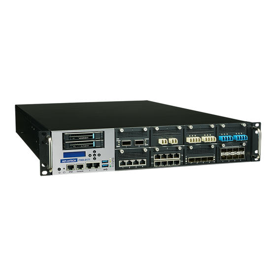
Page 12: System Outlook
Figure 1: System Front View 1.2.2 3 redundant fan module and 2 redundant power supply locate symmetrically and 1 D-sub VGA on back of chassis. Figure 2: System Rear View Copyright 2014 Advantech Co. Ltd. All rights reserved. -
Page 13: System Layout
System layout System layout as below picture Figure 3: System Architecture Copyright 2014 Advantech Co. Ltd. All rights reserved. -
Page 14: Block Diagram
Block Diagram Copyright 2014 Advantech Co. Ltd. All rights reserved. -
Page 15: Component Installation
1.5.1 CPU & H EATSINK FWA-6171 main board supports dual-socket INTEL® XEON® scalable processor family with LGA4189 socket. For details of the XEON® scalable processor, please refer to Intel. Please follow Intel’s instruction to install Xeon on FWA-6171 main board. -
Page 16: Memory
Tighten screw by the instruction on heatsink sticker as below. 1.5.2 EMORY FWA-6171 supports up to 32 DIMMs with 3200 MHz memory ECC RDIMM. For the location of the memory modules, see system layout section. Suggest check following link for install DIMM in FWA-6171 https://advantech-ncg.zendesk.com/hc/en-us/articles/4407410241549-FWA-6171-DIMM-module-... -
Page 17: 2.5" Sata Hdd/Ssd
1.5.3 2.5” SATA HDD/SSD FWA-6171 supports 2*2.5” SATA HDD/SSD install in internal HDD module and 4* M.2 2280 SSD on main board and management board. Step 1. Put 2.5" SATA HDD on HDD tray. Step 2. Put 2.5" SATA HDD tray on HDD module. -
Page 18: Pcie
1.5.4 FWA-6171 reserves two PCIe slot one for Full height and half-length PCIe and one for low-profile PCIe add-on cards running on PCIe Gen4 x8 or one Full height and half-length PCIe Gen4 x16 by system SKUs. Step 1. Put PCIe add-on cards on PCIe module Step 2. -
Page 19: Optimum Mounting Environment
Step 3. Install PCIe module on main board with screw as arrow indicate. Optimum Mounting Environment 1.6.1 PACE EQUIREMENT Please always keep 20cm space around platform for better thermal dissipation if not running FWA-6171 on rack. 1.6.2 EMPERATURE EQUIREMENT Please make sure environment condition before power on this system: ... -
Page 20: Rack Mounting Instructions
Rack Mounting Instructions 1.7.1 VERVIEW OF THE AILS FWA-6171 use 438mm wide rail kit for rack mounting. 1.7.2 NSTALLING THE AILS ON Remove the chassis (inner) member Mount the chassis (inner) member to chassis _20220127_JH.DOCX User Manual_FWA-6171 Copyright 2017 Advantech Co. Ltd. All rights reserved. - Page 21 Attach the cabinet (outer) member to the rail _20220127_JH.DOCX User Manual_FWA-6171 Copyright 2017 Advantech Co. Ltd. All rights reserved. Page 21...
- Page 22 Mount the chassis into the cabinet _20220127_JH.DOCX User Manual_FWA-6171 Copyright 2017 Advantech Co. Ltd. All rights reserved. Page 22...
-
Page 23: Chassis Installation
Therefore, consideration should be given to installing the equipment in an environment compatible with the maximum recommended ambient temperature. _20220127_JH.DOCX User Manual_FWA-6171 Copyright 2017 Advantech Co. Ltd. All rights reserved. Page 23... -
Page 24: Install/Remove Nmc Component
Install/remove NMC component FWA-6171 supports up to 8 Network Mezzanine Cards (NMCs) space. Put NMC alone with guiding rail and insert into chassis. Install/remove Power Supply component Power supply unit is modularize design for FWA-6171. Please install as below instruction. -
Page 25: Install/Remove Fan Module
1.10 Install/remove Fan module Fan modular can be swappable with N+1 redundant design for FWA-6171. Please install as below instruction. _20220127_JH.DOCX User Manual_FWA-6171 Copyright 2017 Advantech Co. Ltd. All rights reserved. Page 25... -
Page 26: Operation
This method forces the server to enter standby mode without properly exiting applications and the OS. If an application stops responding, you can use this method to force a shutdown. _20220127_JH.DOCX User Manual_FWA-6171 Copyright 2017 Advantech Co. Ltd. All rights reserved. Page 26... -
Page 27: Booting From Network Via Pxe
Below are the steps to enable UEFI PXE boot. 1. It needs to set BIOS/ Advanced-> Network Stack Configuration-> Network Stack as enabled (default setting is disabled) & UEFI PXE Support as enabled Copyright 2014 Advantech Co. Ltd. All rights reserved. - Page 28 Below are the steps to Legacy PXE boot. 1. It needs to set BIOS/ Advanced-> Network Stack Configuration-> Network Stack as disabled (default setting is disabled) _20220127_JH.DOCX User Manual_FWA-6171 Copyright 2017 Advantech Co. Ltd. All rights reserved. Page 28...
- Page 29 BBS Priorities” item and set Legacy PXE LAN boot sequence priority. And please choose Legacy Boot priority as “IBA GE Slot 0100 v1570” it is on board Mgmt1 GbE port. _20220127_JH.DOCX User Manual_FWA-6171 Copyright 2017 Advantech Co. Ltd. All rights reserved. Page 29...
- Page 30 Please note that it is recommended to setup a separate network / subnet for network booting as the DHCP required for PXE booting may conflict with existing DHCP servers in your network. _20220127_JH.DOCX User Manual_FWA-6171 Copyright 2017 Advantech Co. Ltd. All rights reserved. Page 30...
-
Page 31: Led Behaviour
LED Behaviour Advantech Advanced LAN bypass uses a LED to show the state of a bypass segment. Usually the bypass LED is implemented as a dual colour LED combined with a regular LAN port LED. The table below shows the status of the bypass LED, only. - Page 32 Primary BIOS flash ROM Socket Secondary BIOS flash ROM Socket CN128 Customer flash ROM Socket RTC battery Socket CN129 Internal BMC UART debug header System Reset Button System Power Button _20220127_JH.DOCX User Manual_FWA-6171 Copyright 2017 Advantech Co. Ltd. All rights reserved. Page 32...
- Page 33 SW1-1 NODE_CTRL Master : PCH OFF (DEFAULT) Normal SW1-2 ME Force Update Release Button (DEFAULT) Normal RTC Press Button Clear RTC Resisters Table 4: NAMB-6171MB Switch Setting _20220127_JH.DOCX User Manual_FWA-6171 Copyright 2017 Advantech Co. Ltd. All rights reserved. Page 33...
-
Page 34: Main Board Led Placement
P5V STBY Power Good indicate LED DSW Power Good indicate LED P3V3 STBY Power Good indicate LED PCH P1V8 Power Good indicate LED D154 PCH PVNN Power Good indicate LED _20220127_JH.DOCX User Manual_FWA-6171 Copyright 2017 Advantech Co. Ltd. All rights reserved. Page 34... - Page 35 Primary BIOS indicate LED LED1 Secondary BIOS indicate LED NAMB-6171MGT LED Indication: MGNT 1/2 & IPMI LED Behavior Green Speed 100M Amber Link Green Activity Green Blinking _20220127_JH.DOCX User Manual_FWA-6171 Copyright 2017 Advantech Co. Ltd. All rights reserved. Page 35...
- Page 36 Drive present, activity Blinking Note1: Green LED will always On or OFF when HDD not access, LED behavior according to drive activity pin(P11) design. Table 6: NAMB-6171MB/MGT/NBP indicate LED _20220127_JH.DOCX User Manual_FWA-6171 Copyright 2017 Advantech Co. Ltd. All rights reserved. Page 36...
-
Page 37: Bios
This section describes the FWA-6171’s UEFI BIOS based on AMI’s APTIO BIOS. Users can modify BIOS settings and control the special features of the FWA-6171 using the BIOS setup menu. Please note that Advantech supports shipping the FWA-6171 with custom BIOS defaults to simplify the deployment and integration for our customers. -
Page 38: Main Setup Menu
BIOS Setup. After a successful check or if password protection has not been enabled, users will see the Main Setup screen shown below. Users can always return to the Main setup screen by selecting the Main tab. _20220127_JH.DOCX User Manual_FWA-6171 Copyright 2017 Advantech Co. Ltd. All rights reserved. Page 38... - Page 39 Shows current NVRAM ver. IPMC Version Display only Shows current BMC ver. System Selects the Setup Menu Language. Only Display only Language English is supported on the FWA-6171. _20220127_JH.DOCX User Manual_FWA-6171 Copyright 2017 Advantech Co. Ltd. All rights reserved. Page 39...
-
Page 40: Platform Setup Menu
ETUP Select the Platform tab from the FWA-6171 setup screen to enter the Platform Setup screen. Users can select any of the items in the left frame of the screen, such as the Trusted Computing Configuration, to go to the sub menu for that item. - Page 41 Data Bits 7 / 8 Defines number of data bits in a character. None / Even / Parity Odd / Mark / Defines the parity scheme used. Space _20220127_JH.DOCX User Manual_FWA-6171 Copyright 2017 Advantech Co. Ltd. All rights reserved. Page 41...
- Page 42 3.2.2.2 USB Configuration This sub menu allows you to change the settings used for USB and to get an overview of the USB devices detected by the BIOS. _20220127_JH.DOCX User Manual_FWA-6171 Copyright 2017 Advantech Co. Ltd. All rights reserved. Page 42...
- Page 43 Please note that Trusted Computing support is disabled by default in the factory defaults to save system boot time. If disabled, the Trusted Computing Menu will not display any status information. _20220127_JH.DOCX User Manual_FWA-6171 Copyright 2017 Advantech Co. Ltd. All rights reserved. Page 43...
- Page 44 When system with TPM2.0 module installed, and the BIOS will auto detect it and the related setting will be shown in the BIOS setup menu as below. _20220127_JH.DOCX User Manual_FWA-6171 Copyright 2017 Advantech Co. Ltd. All rights reserved. Page 44...
- Page 45 Enable Platform Enable or Disable Platform Hierarchy Hierarchy Disable Enable Storage Hierarchy Enable or Disable Storage Hierarchy Disable Enable Endorsement Enable or Disable Endorsement Hierarchy Hierarchy Disable _20220127_JH.DOCX User Manual_FWA-6171 Copyright 2017 Advantech Co. Ltd. All rights reserved. Page 45...
- Page 46 When system with TPM1.2 module installed, and the BIOS will auto detect it and the related setting will be shown in the BIOS setup menu as below. Figure 12: Platform Setup: Trusted Computing with TPM1.2 _20220127_JH.DOCX User Manual_FWA-6171 Copyright 2017 Advantech Co. Ltd. All rights reserved. Page 46...
- Page 47 This sub menu allows you to see all the H/W monitor items detected by the BIOS when system is without BMC, for well know the current system health status. Figure 13: Platform Setup: H/W monitor _20220127_JH.DOCX User Manual_FWA-6171 Copyright 2017 Advantech Co. Ltd. All rights reserved. Page 47...
- Page 48 This sub menu allows you to change the settings used for related CPU utilization setting. The default configuration for CPU was optimized setting for getting better performance for networking, so it is not recommend to change it. _20220127_JH.DOCX User Manual_FWA-6171 Copyright 2017 Advantech Co. Ltd. All rights reserved. Page 48...
- Page 49 Hardware P- based on OS Request (Legacy P-States) States Native Mode Native Mode: Hardware chooses a P-state Out of Band based on OS guidance Out of Band Mode _20220127_JH.DOCX User Manual_FWA-6171 Copyright 2017 Advantech Co. Ltd. All rights reserved. Page 49...
- Page 50 Figure 16 SW Button Mode manual Access / Group Setup item Description Options Sleep Button None SW Button Mode Driver Config Software Button Disabled Table 9: SW Button Mode manual _20220127_JH.DOCX User Manual_FWA-6171 Copyright 2017 Advantech Co. Ltd. All rights reserved. Page 50...
- Page 51 3.2.2.8 Advantech Lan Byapss configuration This sub menu allows you to change the settings used for related Advantech Lan Byapss settings of NMC modules. Figure 17: Lan Byapss settings Access / Group Setup item Description Options Config Lan None Bypass Devices...
-
Page 52: Hardware Setup Menu
Select the action of Lan bypass for NMC Disconnect When System Reset Bypass Table 10: Advantech Lan Bypass Menu 3.2.3 H ARDWARE SETUP MENU This sub menu allows you to change the settings of the Intel chipset. Please note that “chipset” is a legacy term and the related functionality is split over the CPU and PCH portions of the SoC. - Page 53 The sub menus are described on the following pages. Figure 18: Hardware Configuration Menu 3.2.3.1 Hardware Setup: CPU Configuration This menu use example of Xeon CPU configuration. _20220127_JH.DOCX User Manual_FWA-6171 Copyright 2017 Advantech Co. Ltd. All rights reserved. Page 53...
- Page 54 (MSR 1A4h [3]). Table 9: Processor Configuration Menu 3.2.3.2 Hardware Setup: North Bridge Configuration This menu allows the configuration of the memory controller and related features of the SoC. _20220127_JH.DOCX User Manual_FWA-6171 Copyright 2017 Advantech Co. Ltd. All rights reserved. Page 54...
- Page 55 Enable/Disable Patrol Scrub Enable at End of POST Enable - Enables data scrambling for DDR4 Disabled Data Scrambling and DDR5. for DD Enabled Disable - Disables this feature. _20220127_JH.DOCX User Manual_FWA-6171 Copyright 2017 Advantech Co. Ltd. All rights reserved. Page 55...
- Page 56 This sub-menu contains settings for the PCIe subsystem. Some menu items are referred to as “PCI” settings. Although the FWA-6171 does not implement a PCI bus, these settings still apply to the platform as PCIe is using the same configuration mechanism as PCI.
- Page 57 Change PCI Express Devices Settings. Speed Gen 3 (8 GT/s) Gen 4 (16 GT/s Auto IOU1 (IIO PCIe Select PCIe port bifurcation x4x4x4x4 Port 1) x4x4x8 x8x4x4 _20220127_JH.DOCX User Manual_FWA-6171 Copyright 2017 Advantech Co. Ltd. All rights reserved. Page 57...
- Page 58 Speed Gen 3 (8 GT/s) Gen 4 (16 GT/s Auto PORT 2C Link Gen 1 (2.5 GT/s) Change PCI Express Devices Settings. Speed Gen 2 (5 GT/s) _20220127_JH.DOCX User Manual_FWA-6171 Copyright 2017 Advantech Co. Ltd. All rights reserved. Page 58...
- Page 59 Port 0) x8x4x4 Socket 1 x8x8 PCIe port control Auto PORT 0A Link Gen 1 (2.5 GT/s) Change PCI Express Devices Settings. Speed Gen 2 (5 GT/s) _20220127_JH.DOCX User Manual_FWA-6171 Copyright 2017 Advantech Co. Ltd. All rights reserved. Page 59...
- Page 60 Change PCI Express Devices Settings. Speed Gen 3 (8 GT/s) Gen 4 (16 GT/s) Auto PORT 1D Link Change PCI Express Devices Settings. Speed Gen 1 (2.5 GT/s) _20220127_JH.DOCX User Manual_FWA-6171 Copyright 2017 Advantech Co. Ltd. All rights reserved. Page 60...
- Page 61 Speed Gen 3 (8 GT/s) Gen 4 (16 GT/s) Auto PORT 3B Link Gen 1 (2.5 GT/s) Change PCI Express Devices Settings. Speed Gen 2 (5 GT/s) _20220127_JH.DOCX User Manual_FWA-6171 Copyright 2017 Advantech Co. Ltd. All rights reserved. Page 61...
- Page 62 Gen 4 (16 GT/s Table 11: Hardware Setup: PCI Subsystem Menu Items 3.2.3.4 UPI Configuration This sub-menu contains settings for the UPI configuration. Figure 21: Hardware Setup: UPI configuration _20220127_JH.DOCX User Manual_FWA-6171 Copyright 2017 Advantech Co. Ltd. All rights reserved. Page 62...
- Page 63 Table 12: Hardware Setup: QPI configuration Menu Items 3.2.3.5 Hardware Setup: South Bridge Configuration This menu contains settings for the South Bridge for related SATA ,and ACPI setting etc. _20220127_JH.DOCX User Manual_FWA-6171 Copyright 2017 Advantech Co. Ltd. All rights reserved. Page 63...
- Page 64 Figure 23: Hardware Setup: SATA configuration Feature Default Description SATA Port0 Display only SATA Port1 Display only Show current SATA devices in use on the FWA-6171 SATA Port2 Display only _20220127_JH.DOCX User Manual_FWA-6171 Copyright 2017 Advantech Co. Ltd. All rights reserved.
- Page 65 Designates this port as Hot Pluggable Disabled Enabled sSATA Hot Plug #Port 1 Designates this port as Hot Pluggable Disabled sSATA Hot Plug #Port 5 Enabled Designates this port as Hot Pluggable _20220127_JH.DOCX User Manual_FWA-6171 Copyright 2017 Advantech Co. Ltd. All rights reserved. Page 65...
- Page 66 Enable the system ability to hibernate Enabled Enable (OS/S4 sleep state), this option may be not Hibernation Disabled effective with some O.S Table 15: Hardware Setup: ACPI configuration Menu Items _20220127_JH.DOCX User Manual_FWA-6171 Copyright 2017 Advantech Co. Ltd. All rights reserved. Page 66...
- Page 67 Group Setup item Description Options Enabled System error enabling and logging setup None System Errors Disabled option Auto Table 16: Hardware Setup: Runtime Error logging Menu Items _20220127_JH.DOCX User Manual_FWA-6171 Copyright 2017 Advantech Co. Ltd. All rights reserved. Page 67...
- Page 68 Figure 27: NVMe configuration 3.2.3.10 Intel® VROC for Volume Management Device Configuration This menu contains settings for Intel® VMD for Volume Management Device Configuration Figure 28:VROC configuration _20220127_JH.DOCX User Manual_FWA-6171 Copyright 2017 Advantech Co. Ltd. All rights reserved. Page 68...
-
Page 69: Server Mgmt Setup Menu
OS Boot Watchdog Timer expires. Reset Policy Not available if OS Boot Watchdog Timer is disabled. Power Down Table 17: Server Mgmt configuration Menu Items _20220127_JH.DOCX User Manual_FWA-6171 Copyright 2017 Advantech Co. Ltd. All rights reserved. Page 69... - Page 70 Router IP address Router MAC address LAN 2 is BMC’s internal USB LAN, and Lan channel Configuration these item are setting by ipmitool StaticAddress Address command _20220127_JH.DOCX User Manual_FWA-6171 Copyright 2017 Advantech Co. Ltd. All rights reserved. Page 70...
- Page 71 Station address Router IP address 0.0.0.0 Router 00-00-00-00-00- address Table 19. BMC network configuration manual 3.2.6 B MC SELF TEST LOG Figure 31: Bmc self test log _20220127_JH.DOCX User Manual_FWA-6171 Copyright 2017 Advantech Co. Ltd. All rights reserved. Page 71...
- Page 72 |Change this to enable or disable all Disabled SEL Components features of System Event Logging during Enabled boot. None Erase SEL Choose options for erasing SEL. Yes, On next reset _20220127_JH.DOCX User Manual_FWA-6171 Copyright 2017 Advantech Co. Ltd. All rights reserved. Page 72...
-
Page 73: Setup Post & Boot Menu
Description Save Changes and Exit setup after saving the changes. Does not update User Exit defaults. None Discard Changes Exit setup without saving any changes. and Exit _20220127_JH.DOCX User Manual_FWA-6171 Copyright 2017 Advantech Co. Ltd. All rights reserved. Page 73... - Page 74 This option allows you to override the specified boot order Boot Override device> and use a different boot device for the next boot. Table 18: Save & Exit Menu Options _20220127_JH.DOCX User Manual_FWA-6171 Copyright 2017 Advantech Co. Ltd. All rights reserved. Page 74...
-
Page 75: Bmc Functionalities
UNCTIONALITIES This chapter list out OEM IPMI commands for reference. OEM IPMI COMMANDS 4.1.1 OMMEND CODE The BMC supported Advantech IPMI OEM commands are listed in below table. Command Name NetFn Code Command Code Get HW Revision Get Payload CPU ID... -
Page 76: Advantech Oem Command 'Store Configuration Settings
Get Core Version Reload Factory Defaults 4.1.2 Advantech OEM Command ‘Store Configuration Settings This command is used to store configuration settings, and it is used to enable or disable the NC-SI “Keep PHY Link Up” setting of the management LAN port. - Page 77 LAN controller: NC-SI “Keep PHY Link Up”: 00h: disable 01h: enable Response Byte Data Field Completion Code 00h: command completed normally IANA Byte 1: 0x39 IANA Byte 2: 0x28 IANA Byte 3: 0x00 _20220127_JH.DOCX User Manual_FWA-6171 Copyright 2017 Advantech Co. Ltd. All rights reserved. Page 77...
-
Page 78: Advantech Oem Command 'Read Configuration Settings
Setting: LAN controller 03h: NC-SI “Keep PHY Link Up” Response Byte Data Field Completion Code 00h: command completed normally IANA Byte 1: 0x39 IANA Byte 2: 0x28 _20220127_JH.DOCX User Manual_FWA-6171 Copyright 2017 Advantech Co. Ltd. All rights reserved. Page 78... - Page 79 IANA Byte 3: 0x00 Setting/Port Bytes LAN controller: NC-SI “Keep PHY Link Up”: 00h: disabled 01h: enabled _20220127_JH.DOCX User Manual_FWA-6171 Copyright 2017 Advantech Co. Ltd. All rights reserved. Page 79...
-
Page 80: Advantech Oem Command 'Sel Mode Configuration
Table 2: ‘Read Configuration Settings’ Command 4.1.4 Advantech OEM Command ‘SEL Mode Configuration This command is used to change System Event Log (SEL) behaviour when the SEL runs full. Two options are available: stop logging when the SEL is full, or roll over (overwrite oldest event in case of new event). -
Page 81: Advantech Oem Command 'Read Port 80 (Bios Post Code)
Wrap around Erase Overwrite the oldest event on SEL when full Immediately 4.1.5 Advantech OEM Command ‘Read Port 80 (BIOS POST Code) This command is used to retrieve the latest BIOS POST Code. Request Byte Data Field NetFn: 0x2e Cmd: 0x80 IANA Byte 1: 0x39 _20220127_JH.DOCX... - Page 82 Command Sequence Description ipmitool raw >ipmitool raw 0x2e 0x80 0x39 0x28 0x00 Read Port 80 (BIOS POST Code) 39 28 00 b2 The latest POST Code is 0xb2 _20220127_JH.DOCX User Manual_FWA-6171 Copyright 2017 Advantech Co. Ltd. All rights reserved. Page 82...
-
Page 83: Advanced Lan By Pass, Bmc Firmware And Bios Upgrade
, BMC FIRMWARE AND BIOS DVANCED LAN BY PASS UPGRADE Advanced lan by pass: Please refer Advanced LAN bypass user manual Advanced_LAN_Bypass_User_Manual: https://www.advantech.com/support/details/manual?id=1-1IRCY5T Please refer to Advantech_QuickStart_Linux_Image_Getting_Started_Guide_FWA_6171 _20220127_JH.DOCX User Manual_FWA-6171 Copyright 2017 Advantech Co. Ltd. All rights reserved. Page 83... -
Page 84: Appendix A : Acknowledgements
Creative is a trademark of Creative Technology LTD. CHRONTEL is a trademark of Chrontel Inc. All other product names or trademarks are properties of their respective owners. _20220127_JH.DOCX User Manual_FWA-6171 Copyright 2017 Advantech Co. Ltd. All rights reserved. Page 84... -
Page 85: Appendix B : Glossary
PCI Industrial Computer Manufacturers Group POST Power On Self Test Power Supply Unit Pre-boot Execution Environment QuickAssist Technology QuickPath Interconnect RASUM Reliability, Availability, Serviceability, Usability, Maintainability RDIMM Registered DIMM _20220127_JH.DOCX User Manual_FWA-6171 Copyright 2017 Advantech Co. Ltd. All rights reserved. Page 85... - Page 86 Sensor Data Record SerDes Serializer/Deserializer Serial Over LAN Solid State Disk Software Trusted Platform Module Transmit UDIMM Unbuffered DIMM UHCI Universal Host Controller Interface Universal Serial Bus _20220127_JH.DOCX User Manual_FWA-6171 Copyright 2017 Advantech Co. Ltd. All rights reserved. Page 86...
Need help?
Do you have a question about the FWA-6171 and is the answer not in the manual?
Questions and answers