Table of Contents
Advertisement
Quick Links
Advertisement
Table of Contents

Related Manuals for 2N Clip 9138512


Summary of Contents for 2N Clip 9138512
- Page 1 2N Clip User Manual...
- Page 2 Abstract...
-
Page 3: Table Of Contents
IP address ..........................20 Web Configuration Interface Login ....................20 IP Address Retrieval ........................20 IP Address Retrieval Using 2N Network Scanner ................. 21 IP Address Retrieval using Device Display .................. 21 IP Address Retrieval Using Hardware ..................22 Firmware Update .......................... 23 Device Restart .......................... - Page 4 Home Screen ..........................53 Directory Menu .......................... 54 Settings Menu ........................... 56 Ringtone Setting Menu ....................... 58 Operational Statuses ........................58 Signaling of Operational Statuses ....................59 Calls ............................60 Idle Mode ..........................62 Device Lock ..........................62 Maintenance - Cleaning ........................64 Troubleshooting ..........................
-
Page 5: Symbols And Terms Used
Symbols and Terms Used Symbols and Terms Used The following symbols and pictograms are used in the manual: DANGER Always abide by this information to prevent persons from injury. WARNING Always abide by this information to prevent damage to the device. CAUTION Important information for system functionality. -
Page 6: Product Description
The section also includes safety precautions. Basic Features 2N Clip is an indoor IP/SIP unit allowing for audio and video communication with the 2N IP intercoms. The device includes a three-button control panel, Speakerphone, high-quality microphone with excellent audibility and intelligibility properties, Ethernet LAN interface and external power supply and doorbell con- nectors. - Page 7 Product Description Part No. 9138003 Axis Part No. 02906-001 Mounting holder Single-Gang Box installation plate for 2N Clip. Not included in the package of 2N Clip. Part No. 9138002 Axis Part No. 02905-001 Stand Stand for 2N Clip. Not included in the package of 2N Clip.
-
Page 8: Device Description
Package Completeness Check (p. 8) • Component Layout (p. 9) Package Completeness Check Please check the product delivery before installation. Contents: 2N Clip Certificate of ownership Quick Start manual Metal holder Holder fitting screws (3 x 12 mm self-tapping lens head screw) -
Page 9: Component Layout
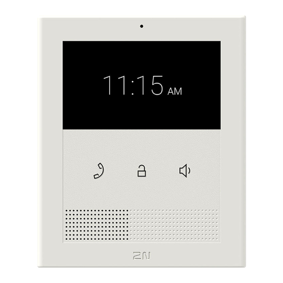
Device Description Component Layout Front Microphone Display Lock button Speaker button Speaker Earphone button... - Page 10 Device Description Rear RESET Button Doorbell Button Input LAN Ethernet/PoE Status LEDs Locking Latch...
-
Page 11: Mechanical Installation
• into a stand (not included in the package). WARNING Having unpacked 2N Clip, remove the metal holder located on the device back side for installation. Use both your hands at the same time to remove the metal holder safely. A careless removal and insufficient push of the locking latch might lead to a locking latch damage. -
Page 12: Wall Installation
Flush Mounting Box Device Installation 2N Clip can be installed into a KU 68 mounting box using an EU metal holder (included in the package), the recommended height of a standard installation being 135 cm above the ground level. The installation heights may vary depending on the device use. - Page 13 You are advised to use a metal holder (not included in the package) for 2N Clip installation in the USA. With the aid of this holder, the device can be installed into universal US single-gang mounting boxes. The device...
- Page 14 Mechanical Installation Download the drilling template from 2N.com. Draw the LAN connector leading from the wall through the metal holder. Make sure that it is properly oriented in terms of device connection after installation. If necessary, align the holder using a level and drill it into the mounting box or on the wall.
-
Page 15: Stand Installation
Connect the doorbell twin cable to the connector together with the LAN connector. WARNING Having unpacked 2N Clip, remove the metal holder located on the device back side for installation. Use both your hands at the same time to remove the metal holder safely. A careless removal and insufficient push of the locking latch might lead to a locking latch damage. - Page 16 Mechanical Installation...
-
Page 17: Device Removal
Remove the device from the hooks and take it away safely. Power Supply 2N Clip is fed via an Ethernet cable connected to a PoE power supply or PoE supporting Ethernet switch/ router. Supply type PoE, IEEE 802.3af, Class 0 (0,44–12,95 W) -
Page 18: Poe Supply Connection
CAUTION Make sure that the external power supply meets the power supply class PS2/LPS. PoE Supply Connection Use a standard straight RJ-45 terminated cable to connect 2N Clip to the Ethernet. The device supports the 10BaseT and 100BaseT protocols. CAUTION •... - Page 19 Mechanical Installation WARNING This device cannot be connected directly to telecom lines (or public wireless networks) of any telecom service providers (i.e. mobile providers, landline providers or Internet provid- ers). A router has to be used for the device Internet connection.
-
Page 20: Brief Guidelines
Call Connection (p. 24) Device Configuration Interface Access 2N Clip is configured via the administration web interface. Connect the device to the LAN IP and make sure it is properly powered. You have to know the IP address for access. -
Page 21: Ip Address Retrieval Using 2N Network Scanner
Brief Guidelines IP Address Retrieval Using 2N Network Scanner The application helps you find the IP addresses of all the 2N devices in the LAN. Download 2N Network Scanner from the 2N.com website. Make sure that Microsoft .NET Framework 2.0 is installed for successful app installation. -
Page 22: Ip Address Retrieval Using Hardware
Brief Guidelines To find the device IP address using the display, press any button to quit the Idle mode. The Settings menu (p. 56) is displayed on the home screen after a long press of the earpiece and speaker buttons. Find the IP address information in the About device menu. IP Address Retrieval Using Hardware Follow the instructions below to retrieve the current IP address: Press and hold the RESET button. -
Page 23: Firmware Update
The delay after pressing RESET till the first light and sound signaling is set to 15–35 s depending on the device model used. Firmware Update We recommend that the firmware is also updated during the 2N Clip installation. Refer to 2N.com for the latest FW version. -
Page 24: Restart Using Web Configuration Interface
Factory Default Reset Follow the instructions below 2N Clip to reset the factory default values: Press and hold the RESET button. Wait until the red and green LEDs go on simultaneously on the device and the acoustic signal can be heard (approx. - Page 25 • starting a call with the contact by a long/short press of the call button • a virtual number to start a call by entering the number via your numerical keypad • basic information Make sure that the call transmitting service is enabled on the called 2N device to make a successful call.
-
Page 26: Configuration
Configuration Configuration 2N Clip can be configured by software via the configuration web interface or by hardware using the RESET button. Hardware configuration is used for basic settings only. • Basic Configuration via Hardware (p. 26) • Software Configuration (p. 29) •... -
Page 27: Static Ip Address Setting
Configuration Wait until the red and green LEDs go on simultaneously on the device and the acoustic signal can be heard (approx. 15–35 s). Release the RESET button. The device announces the current IP address via the speaker automatically. NOTE The delay after pressing RESET till the first light and sound signaling is set to 15–35 s depending on the device model used. -
Page 28: Dynamic Ip Address Setting
Release the RESET button. Factory Default Reset Follow the instructions below 2N Clip to reset the factory default values: Press and hold the RESET button. Wait until the red and green LEDs go on simultaneously on the device and the acoustic signal can be heard (approx. -
Page 29: Software Configuration
Help or use the bubble to provide feedback. Legend The start screen is also the first menu level and quick navigation (click on a tile) to selected 2N Clip configuration sections. -
Page 30: Device Configuration Interface Access
Configuration Device Configuration Interface Access 2N Clip is configured via the administration web interface. Connect the device to the LAN IP and make sure it is properly powered. You have to know the IP address for access. Domain Name Enter the domain name as “hostname.local”. The new device Hostname consists of the device name and serial number. -
Page 31: State
Configuration Web Configuration Interface Login Fill in the 2N Clip address or domain name into the internet browser. The login screen is now displayed. Should the login screen fail to appear, you must have typed a wrong IP address, port, domain name or the administration web server has been switched off. -
Page 32: Directory
Change of the SIP Proxy registration state. Directory Directory is one of the crucial parts of the device configuration. It helps you add new devices (2N IP intercoms, answering units, etc.). Up to 200 devices can be added to the directory. - Page 33 Up to 10,000 users can be imported depending on the device type. CAUTION • Special users such as those created by My2N or 2N Access Commander are not part of the directory export. • While editing the CSV file using Microsoft Excel, remember to save the file in the CSV UTF-8 format (with separators).
-
Page 34: Calling
DTMF character via a phone. The supported characters also include * or #. Four characters at least are recommended. Calling Calling is the basic function of 2N Clip – helps you establish connections with other IP network terminal devices. The device supports the extended SIP. The Call section consists of the following menus: •... - Page 35 SIP 1 / SIP 2 2N Clip allows two independent SIP accounts to be configured. Thus, the intercom can be registered under two phone numbers at the same time, with two different SIP exchanges, for example. Both the SIP accounts process incoming calls equivalently.
- Page 36 Configuration Failure Reason – display the reason for the last registration attempt failure: the registrar’s last error reply, e.g. 404 Not Found. Advanced Settings SIP Transport Protocol – set the SIP communication protocol: UDP (default), TCP or TLS. Lowest Allowed TLS Version – set the lowest TLS version to be accepted for device connection. Verify Server Certificate –...
- Page 37 Configuration RTP Timeout – set the audio stream RTP packet receiving timeout during a call. If this limit is exceeded (RTP packets are not delivered), the call will be terminated by the device. Enter 0 to disable this parameter. The parameter is only set for account 1 but applies to both the SIP accounts. Broadsoft Compatibility Mode –...
-
Page 38: Services
Network Identification Device ID – set the device ID to be displayed in the LAN device list in all the 2N devices in one and the same LAN. You can direct a call to this device by setting the user phone number as “device:device_ID” in these devices. -
Page 39: Hardware
• Doorbell – set the sound to be played when the door button is pressed. Web Server 2N Clip can be configured using a common browser that approaches the web server integrated in the device. The HTTPS protocol is used for the browser - device communication. - Page 40 Configuration Audio 2N Clip is equipped with a speaker. Set the phone call and state signaling volume control in this configura- tion section. Master Volume (adjusted using ) controls the general device volume affecting both the call volume and the signaling tone volume.
-
Page 41: System
Maintenance (p. 47) Network 2N Clip is connected to the LAN and has to be assigned a valid IP address or obtain the IP address from the LAN DCHP server. The Network section helps you configure the IP address and DHCP. - Page 42 Configuration DNS Setting Always Use Manual Setting – enable manual setting of the DNS server addresses. Primary DNS – primary DNS address for domain name-to-IP address translation. Secondary DNS – secondary DNS address where the primary DNS is unavailable. Network Identification Hostname –...
- Page 43 Configuration Date and Time Clip equipped with real time clock without power outage backup. Select Use Time from Internet (p. 0 to synchronize the device time with the Internet time or click Synchronize with Browser to synchronize time with your current PC time. NOTE The device does not need the current date and time values for its basic function.
- Page 44 The beta functions are provided for testing purposes exclusively. Certificates Some 2N Clip LAN services use the secure TLS protocol for communication with the other LAN devices. This protocol prevents third parties from eavesdropping on or modifying call contents. TLS is based on one/two-sided authentication, which requires certificates and private keys.
- Page 45 P-256) and secp384r1 (aka NIST P-384) curves only. Auto Provisioning My2N The My2N cloud platform is used for remote administration and configuration of the 2N IP devices and helps you remotely connect to the device web interface. My2N Enabled – enable connection to My2N.
- Page 46 Configuration Diagnostics Diagnostics The interface allows you to capture diagnostic logs to be downloaded and sent to the Technical support subsequently. The diagnostic logs help identify and solve reported troubles. The logs include information on the device and its configuration, LAN operations, crash log and memory statistics. Diagnostic Package Packet Capture Status –...
- Page 47 Syslog 2N Clip allows you to send system messages to the Syslog server including relevant information on the device states and processes for recording and subsequent analysis and audit. It is unnecessary to configure this service for common operations.
- Page 48 Download the current firmware version for your device from 2N.com. The FW upgrade does not affect configuration. The device checks the firmware file and prevents you from uploading an incorrect or corrupt file.
-
Page 49: Used Ports
Configuration Used Ports Service Port Proto- Direc- On by Config- Settings tion default urable 802.1x – – In/Out × × – DHCP In/Out ✓ × – TCP/U In/Out ✓ × – ✓ Echo (device discov- 8002 In/Out × – ery)* ✓... - Page 50 Configuration Service Port Proto- Direc- On by Config- Settings tion default urable SIPS 5061 In/Out × ✓ Calling Syslog × × – ✓ My2N Knocker × – My2N Tribble Tunnel 10080 ✓ × – Unitchannel 8011 In/Out ✓ × – Sitechannel (ICU pro- 8004 In/Out...
-
Page 51: Device Control
Device Control Device Control There are 3 buttons on the device front side for basic control of the device: • – the earphone button is primarily used for starting an outgoing and receiving/rejecting an incoming call, • – the lock button is primarily used for unlocking the set device, •... - Page 52 Device Control Button Press type Generated action Short press Outgoing call to device A (see the note below for setting details). Long press Outgoing call to device B (see the note below for setting details). Short press Unlocking of device A lock (see the note below for setting details). Long press Unlocking of device B lock (see the note below for setting details).
-
Page 53: Home Screen
Device Control • Idle Mode (p. 62), • Device Lock (p. 62). Home Screen The home screen is set as the start screen of the device, which is displayed whenever the device is activated by a or button press in the Idle mode. Its appearance depends on the device configura- tion, see below. -
Page 54: Directory Menu
Device Control Directory Menu If 2 or more devices are added to 2N Clip, the Di- rectory menu is displayed as introduction instead of the home screen. The Directory menu helps you display 2 devices – device A and device B. - Page 55 Device Control Possible actions Performance Action result Outgoing call to device A Call to device A is started. Short press of Outgoing call to device B Call to device B is started. Long press Device A unlocking Device A lock is unlocked. Short press of Device B unlocking Device B lock is unlocked.
-
Page 56: Settings Menu
Device Control Settings Menu After a long press of buttons , the home screen displays the Settings menu. The Settings menu helps you set the device lo- cally and contains a context menu in the bottom part, which is controlled using the device buttons. The Settings menu makes it possible to: •... - Page 57 Device Control Possible ac- Performance Action result tions Return to home by a short press of The selection is cancelled and the menu actions are ter- screen minated without saving. or in 10 seconds without any button being pressed, or after a call if any. Back (return to Navigation to the preceding menu section.
-
Page 58: Ringtone Setting Menu
Operational Statuses This section includes a basic description of user scenarios and states that can occur during the use of 2N Clip, a list of user options in variable states and expected results of these actions. • Signaling of Operational Statuses (p. 59) •... -
Page 59: Signaling Of Operational Statuses
Device Control • Device Lock (p. 62) Signaling of Operational Statuses The device generates sounds to signal changes of and switching between operational statuses. Each status change is assigned a different type of tone. See the table below for the list of signals. Sound State signaling... -
Page 60: Calls
Device Control Calls In this state, connection or connection attempt is in progress with another device. The 2N Clip functions are limited, it is impossible to switch to the home page and go to menus. Possible actions are included in the table below. - Page 61 Device Control Possible ac- Perform- Action result tions ance Incoming call Connection with the other device has been established, a call is in receiving progress. The call cannot be ended until answered. End of call The active call is interrupted. The call cannot be ended until answered.
-
Page 62: Idle Mode
Device Control Idle Mode 2N Clip transits into the Idle mode after a set inactivity period. Set the inactivity timeout in Dis- play (p. 40) > Backlight of the web configuration or through the device control settings in Settings Menu (p. - Page 63 Device Control Possible actions Performance Action result Device lock activa- The lock is activated. tion Simultaneous press of for 3 seconds Device lock deacti- The device is unlocked and you can vation go to other operational statuses and perform other actions. Simultaneous press of for 3 seconds...
-
Page 64: Maintenance - Cleaning
Maintenance - Cleaning Maintenance - Cleaning If used frequently, the device surface gets dirty. Use a piece of soft cloth moistened with clean water to clean the device. It is recommended that the principles below are followed while cleaning: • Use appropriate cleaning agents suitable for glasses, optical devices, screens, etc. •... -
Page 65: Troubleshooting
Troubleshooting Troubleshooting Refer to faq.2n.cz for the most frequently solved problems. -
Page 66: Technical Parameters
Technical Parameters Technical Parameters Supply type PoE, IEEE 802.3af, Class 0 (0,44–12,95 W) Power Consumption Stand-by mode with display off 1,2 W Stand-by mode with display on 2.0 W Calls without audio 2.4 W Calls with audio 4.4 W Calls with induction loop 6.4 W User interface Controls... - Page 67 Technical Parameters Audio Microphone Integrated Speaker 3 Wintegrated Induction loop output NO (induction loop integration depends on the product version) Audio stream Prootocols Codecs PCMU, PCMA, G.729, G.722, L16/16kHz Video stream Protocols RTP, RTSP, HTTP Codecs H.264 Video Resolution 480 x 272 px Frame rate up to 15 frames per s Interface...
- Page 68 Technical Parameters Doorbell input Input type Switching contact (button/relay) Contact type Normally open (NO) Contact parameters Min. 120 V / 20 mA, DC Mechanical Parameters Dimensions (w x h x 124 x 150 x 26 mm Weight 295 g Operating tempera- 0 to 50 °C ture...
-
Page 69: Directives, Laws And Regulations - General Instructions And Cautions
Directives, Laws and Regulations - General Instructions and Cautions Directives, Laws and Regulations - General Instructions and Cautions 2N Clip conforms to the following directives and regulations: • 2014/35/EU for electrical equipment designed for use within certain voltage limits • 2014/30/EU for electromagnetic compatibility •... - Page 70 / devices of other suppliers, the customer agrees that the 2N TELEKOMUNIKACE a.s. company shall not be held liable for any functionality limitation of such a product or any damage, loss or injury related to this potential functionali- ty limitation.
-
Page 71: Electric Waste And Used Battery Pack Handling
Directives, Laws and Regulations - General Instructions and Cautions All applicable legal regulations concerning the product installation and use as well as provisions of technical standards on electric installations have to be obeyed. The manufacturer shall not be liable and responsible for damage or destruction of the product or damage incurred by the consumer in case the product is used and handled contrary to the said regulations and provisions. - Page 72 2N Clip – User Manual © 2N Telekomunikace a. s., 2024 2N.com...
Need help?
Do you have a question about the Clip 9138512 and is the answer not in the manual?
Questions and answers