Table of Contents

Subscribe to Our Youtube Channel
Related Manuals for Champion Phlebotomy Sprit BDC


Summary of Contents for Champion Phlebotomy Sprit BDC
- Page 1 OWNER'S OPERATING AND MAINTENANCE MANUAL Spirit BDC Solace BDC (2572/2573) (2570/2571) Unity BDC Shown: 2570 Shown: 2572 (2574/2575) Shown: 2574 Phlebotomy Collection 1-800-237-3377 CHAMPIONCHAIR.COM Document No. 006020 Rev R...
- Page 2 Champion assumes no responsibility for damage or injury caused by improper assembly, instal- lation, use, or maintenance of these products. No part of this manual may be duplicated in any form without the prior consent of Champion Manufacturing, Inc . Unauthorized duplication/distribution of these materials may result in civil prosecution to the maximum extent allowed by law.
-
Page 3: Table Of Contents
TABLE OF CONTENTS Important Safety Information ..................... 6 Intended Use Statement ......................5 Transportation, Storage, Handling & Disposal Instructions ..........5 GENERAL CARE & CLEANING ....................... 6 Tools Required ..........................7 SPIRIT BDC: MODEL 2570/2571 ....................8 Glide Foot Installation ......................8 Seat Installation ........................ - Page 4 6. STAY CLEAR of moving parts. 7. DO NOT use chair for transporting in or with ANY type of vehicle or trailer. Champion chairs have not been tested or approved for use by an occupant in any type of vehicle or trailer.
-
Page 5: Intended Use Statement
INTENDED USE STATEMENT The Champion Blood Drawing Chair is a chair intended for use in medical settings. It is designed without wheels and is not electrically powered. It is intended for use in blood donation, collection, or sampling procedures. TRANSPORTATION, STORAGE, HANDLING & DISPOSAL •... -
Page 6: Important Safety Information
GENERAL CARE & CLEANING • Periodically inspect tightness of all screws, bolts, nuts, or other fasteners. Champion Manufacturing, Inc’s full-line of products are built to provide durability and reliability when properly cared for. In general all of our products should be: 1. Cleaned 2. -
Page 7: Tools Required
6. DO NOT install, maintain or operate this equipment without reading and following this manual otherwise injury and/or damage may result. IF YOU HAVE QUESTIONS OR CONCERNS PLEASE CONTACT Champion Manufacturing, Inc . CHAMPION ASSUMES NO RESPONSIBILITY FOR DAMAGE OR INJURY CAUSED BY IMPROPER ASSEMBLY, INSTALLATION, USE, OR MAINTENANCE OF THESE PRODUCTS. -
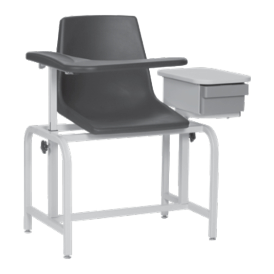
Page 8: Spirit Bdc: Model 2570/2571
SPIRIT BDC: MODEL 2570/2571 SHOWN: Model 2570 Spirit BDC SHOWN: Model 2571 Spirit BDC with Cabinet with Standard Arm GLIDE FOOT INSTALLATION 1. Place chair on side and install four (4) Glide Feet in threaded holes on the bottom of the Chair Frame (FIG. 1 &... -
Page 9: Seat Installation
SEAT INSTALLATION Failure to completely tighten the seat mounting screws COULD RESULT IN SERIOUS WARNING INJURY. 1. Position Chair Frame in upright position. Check tightness of all installed screws, bolts, nuts and other fasteners in case they loosened during shipping. 2. -
Page 10: Arm Assembly And Installation
ARM ASSEMBLY AND INSTALLATION 1. If the Arm Assembly has not yet been installed, insert it into the Receiving Tube on the Seat Frame Assembly (FIG. 1). This applies to any style arm assembly. ALWAYS make sure that the slot in the Arm Assembly faces the Knob installed on the receiving tube •... -
Page 11: Urethane Flip-Up Arm Level Adjustments
URETHANE FLIP-UP ARM LEVEL ADJUSTMENTS Use a ⅛” Hex Key to make minor leveling adjustments to the Urethane Flip-Up Armrest as needed. 1. Rest the Hinge Plate flat on the Hinge Arm Support Bracket. 2. Insert the ⅛” Hex Key into the underlying access hole as shown and turn the screw located inside clockwise until the screw is firmly pressed against the Arm’s Hinge Plate (FIG. -
Page 12: Cabinet Assembly And Installation
CABINET ASSEMBLY AND INSTALLATION * MODEL 2570 1. Remove the cabinet from the frame (FIG. 1). Use CAUTION to avoid personal injury or damaging the product. FIG. 1 2. Remove packaging materials from cabinet assembly. 3. The cabinet installs on the PATIENT LEFT side of chair (FIG. 2). Insert the cabinet assembly into the receiving tube. -
Page 13: Removing And Re-Installing Cabinet Drawer
REMOVING AND RE-INSTALLING CABINET DRAWER * MODEL 2570 1. To remove drawer, open drawer until the drawer stops. Using your finger, locate the drawer stop tab mounted to the bottom of the drawer top. Press the tab against the drawer top and slide the drawer past the tab (FIG. -
Page 14: Pivot Arm Pivot-Point Adjustment
PIVOT ARM PIVOT-POINT ADJUSTMENT Your Pivot Arm Assembly may be configured in one of two (2) directions: • Pivot point located near the back of the chair. This will provide arm support that is straight or at a slight angle to the side of the patient (standard position) (FIG. -
Page 15: Solace Bdc: Model 2572/2573
SOLACE BDC: MODEL 2572/2573 SHOWN: Model 2572 Solace BDC with SHOWN: Model 2573 Solace BDC Cabinet with Standard Arm GLIDE FOOT INSTALLATION 1. Place chair on side and install four (4) Glide Feet in threaded holes on the bottom of the Chair Frame (FIG. 1 &... -
Page 16: Seat Installation
SEAT INSTALLATION WARNING Failure to completely tighten the seat mounting screws COULD RESULT IN SERIOUS INJURY. 1. Position Chair Frame in upright position. Check tightness of all installed screws, bolts, nuts and other fasteners in case they loosened during shipping. 2. -
Page 17: Arm Assembly And Installation
ARM ASSEMBLY AND INSTALLATION 1. If the Arm Assembly has not yet been installed, insert it into the Receiving Tube on the Seat Frame Assembly (FIG. 1). This applies to any style arm assembly. ALWAYS make sure that the slot in the Arm Assembly faces the Knob installed on the receiving tube •... -
Page 18: Urethane Flip-Up Arm Level Adjustments
URETHANE FLIP-UP ARM LEVEL ADJUSTMENTS Use a ⅛” Hex Key to make minor leveling adjustments to the Urethane Flip-Up Armrest as needed. 1. Rest the Hinge Plate flat on the Hinge Arm Support Bracket. 2. Insert the ⅛” Hex Key into the underlying access hole as shown and turn the screw located inside clockwise until the screw is firmly pressed against the Arm’s Hinge Plate (FIG. -
Page 19: Cabinet Assembly And Installation
CABINET ASSEMBLY AND INSTALLATION * MODEL 2572 1. Remove the cabinet from the frame (FIG. 1). Use CAUTION to avoid personal injury or damaging the product. FIG. 1 2. Remove packaging materials from cabinet assembly. 3. The cabinet installs on the PATIENT LEFT side of chair (FIG. 2). Insert the cabinet assembly into the receiving tube. -
Page 20: Removing And Re-Installing Cabinet Drawer
REMOVING AND RE-INSTALLING CABINET DRAWER * MODEL 2572 1. To remove drawer, open drawer until the drawer stops. Using your finger, locate the drawer stop tab mounted to the bottom of the drawer top. Press the tab against the drawer top and slide the drawer past the tab (FIG. -
Page 21: Pivot Arm Pivot-Point Adjustment
PIVOT ARM PIVOT-POINT ADJUSTMENT Your Pivot Arm Assembly may be configured in one of two (2) directions: • Pivot point located near the back of the chair. This will provide arm support that is straight or at a slight angle to the side of the patient (standard position) (FIG. -
Page 22: Unity Bdc: Model 2574/2575
UNITY BDC: MODEL 2574/2575 SHOWN: Model 2574 Unity BDC with SHOWN: Model 2575 Unity BDC Cabinet with Standard Arm GLIDE FOOT INSTALLATION 1. Place chair on side and install four (4) Glide Feet in threaded holes on the bottom of the Chair Frame (FIG. 1 &... -
Page 23: Seat Installation
SEAT INSTALLATION WARNING Failure to completely tighten the seat mounting screws COULD RESULT IN SERIOUS INJURY. 1. Position Chair Frame in upright position. Check tightness of all installed screws, bolts, nuts and other fasteners in case they loosened during shipping. 2. -
Page 24: Arm Assembly And Installation
ARM ASSEMBLY AND INSTALLATION 1. If the Arm Assembly has not yet been installed, insert it into the Receiving Tube on the Seat Frame Assembly (FIG. 1). This applies to any style arm assembly. ALWAYS make sure that the slot in the Arm Assembly faces the Knob installed on the receiving tube •... -
Page 25: Urethane Flip-Up Arm Level Adjustments
URETHANE FLIP-UP ARM LEVEL ADJUSTMENTS Use a ⅛” Hex Key to make minor leveling adjustments to the Urethane Flip-Up Armrest as needed. 1. Rest the Hinge Plate flat on the Hinge Arm Support Bracket. 2. Insert the ⅛” Hex Key into the underlying access hole as shown and turn the screw located inside clockwise until the screw is firmly pressed against the Arm’s Hinge Plate (FIG. -
Page 26: Cabinet Assembly And Installation
CABINET ASSEMBLY AND INSTALLATION * MODEL 2574 1. Remove the cabinet from the frame (FIG. 1). Use CAUTION to avoid personal injury or damaging the product. FIG. 1 2. Remove packaging materials from cabinet assembly. 3. The cabinet installs on the PATIENT LEFT side of chair (FIG. 2). Insert the cabinet assembly into the receiving tube. -
Page 27: Removing And Re-Installing Cabinet Drawer
REMOVING AND RE-INSTALLING CABINET DRAWER * MODEL 2574 1. To remove drawer, open drawer until the drawer stops. Using your finger, locate the drawer stop tab mounted to the bottom of the drawer top. Press the tab against the drawer top and slide the drawer past the tab (FIG. -
Page 28: Pivot Arm Pivot-Point Adjustment
PIVOT ARM PIVOT-POINT ADJUSTMENT Your Pivot Arm Assembly may be configured in one of two (2) directions: • Pivot point located near the back of the chair. This will provide arm support that is straight or at a slight angle to the side of the patient (standard position) (FIG. - Page 29 We reserve the right to add or delete products at any time and without prior notice. Always provide your product's specific serial number when ordering any replacement parts. When in doubt, contact a Champion representative (352-854-2929 or 1-800-237-3377) for further information.
- Page 30 Information contained in this document is based on the latest product data available at the time of printing. Photography, artwork, text and specifications are subject to change. Photographs may show optional items. Champion Manufacturing Inc. reserves the right to make changes to products, materials, options, and/or specification at any time without notice or obligation. Always provide your product's specific serial number when ordering replacement parts.
Need help?
Do you have a question about the Phlebotomy Sprit BDC and is the answer not in the manual?
Questions and answers