Sign In
Upload
Download
Table of Contents
Contents
Add to my manuals
Delete from my manuals
Share
URL of this page:
HTML Link:
Bookmark this page
Add
Manual will be automatically added to "My Manuals"
Print this page
×
Bookmark added
×
Added to my manuals
Manuals
Brands
Champion Manuals
Indoor Furnishing
Care Cliner
Owner's operating and maintenance manual
Champion Care Cliner Owner's Operating And Maintenance Manual
Hide thumbs
1
2
Table Of Contents
3
4
5
6
7
8
9
10
11
12
13
14
15
16
17
18
19
20
21
22
23
page
of
23
Go
/
23
Contents
Table of Contents
Bookmarks
Table of Contents
Table of Contents
Intended Use Statement
Transportation, Storage, Handling and Disposal
Unpacking
Important Safety Information
Products with Powered Options (Heat, Heat & Massage, Etc.)
Isolation Diagram for Heat & Massage System
All Care Cliner Models
Back Assembly Instructions
Operating Instructions
Reclining the Care Cliner
Returning Care Cliner to the Upright Position
Lock/Unlock Casters
Raise/Lower Drop-Arms
Side Panel Removal (Non Drop-Arm Models)
Drop-Arm Vinyl Panel Removal
Side Table Positioning
Using Heat/Heat & Massage Option
General Maintenance
Adjusting the Gas Spring
Adjusting the Recliner Mechanisms
Replacing the Recliner Mechanism
General Care & Cleaning
Specifications
6530 Care Cliner
6540 XL Care Cliner
6550 Drop Arm
6570 XL Drop Arm
Options
Advertisement
Quick Links
Download this manual
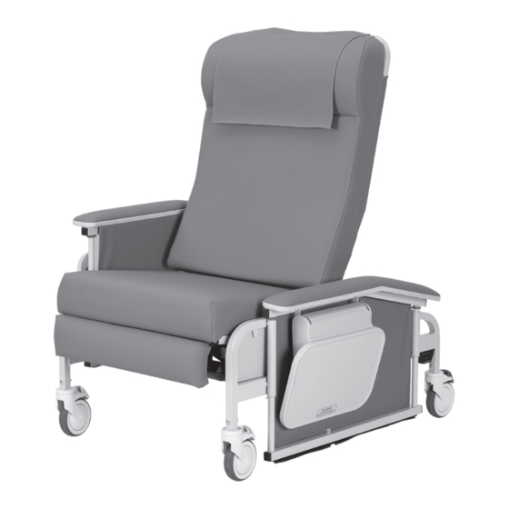
OWNER'S OPERATING AND MAINTENANCE MANUAL
Care Cliner &
XL Care Cliner
(653/654)
Drop-Arm & XL Drop Arm
Care Cliner
(655/657)
Care Cliner Collection
1-800-237-3377
CHAMPIONCHAIR.COM
Document No. 006121 Rev AE
Table of
Contents
Previous
Page
Next
Page
1
2
3
4
5
Advertisement
Table of Contents
Need help?
Do you have a question about the Care Cliner and is the answer not in the manual?
Ask a question
Questions and answers
Related Manuals for Champion Care Cliner
Indoor Furnishing Champion CONTINUUM Operating Instructions And Service Manual
Recliner (26 pages)
Indoor Furnishing Champion ASCENT Operating Instructions And Service Manual
Classic series (39 pages)
Indoor Furnishing Champion Overnighter Series Operating Instructions And Service Manual
Sleeper chairs (18 pages)
Indoor Furnishing Champion T3 Owner's Operating And Maintenance Manual
Procedure chair (28 pages)
Indoor Furnishing Champion TMM3 Owner's Operating And Maintenance Manual
Procedure-chair (31 pages)
Indoor Furnishing Champion Siesta Key Owner's Operating And Maintenance Manual
Sleeper chair (14 pages)
Indoor Furnishing Champion Elevate Operating Instructions And Service Manual
(30 pages)
Indoor Furnishing Champion PASSAGE Operating Instructions And Service Manual
Recliner (30 pages)
Indoor Furnishing Champion 8500 Owner's Operating And Maintenance Manual
Treatment tables (17 pages)
Indoor Furnishing Champion 505 Owner's Operating And Maintenance Manual
(13 pages)
Indoor Furnishing Champion Modular Series Use And Installation
Fixed drawer cabinets (6 pages)
Indoor Furnishing Champion MRA180 Specifications
Table systems for rack conveyor series dishwashing machine (4 pages)
Indoor Furnishing Champion Augustine Owner's Operating And Maintenance Manual
Treatment recliner (31 pages)
Indoor Furnishing Champion Concord 220 Series Operating Instructions And Service Manual
Recliner chair (25 pages)
This manual is also suitable for:
Xl care cliner
Drop-arm care cliner
Xl drop-arm care cliner
653
654
655
...
Show all
657
Table of Contents
Print
Rename the bookmark
Delete bookmark?
Delete from my manuals?
Login
Sign In
OR
Sign in with Facebook
Sign in with Google
Upload manual
Upload from disk
Upload from URL


Need help?
Do you have a question about the Care Cliner and is the answer not in the manual?
Questions and answers