Table of Contents
Advertisement
Quick Links
Advertisement
Table of Contents

Related Manuals for Supermicro SuperStorage 2029P-DN2R24L


Summary of Contents for Supermicro SuperStorage 2029P-DN2R24L
- Page 1 SuperStorage Server 2029P-DN2R24L USER’S MANUAL Revision 1.0b...
- Page 2 State of California, USA. The State of California, County of Santa Clara shall be the exclusive venue for the resolution of any such disputes. Supermicro's total liability for all claims will not exceed the price paid for the hardware product.
- Page 3 If you have any questions, please contact our support team at: support@supermicro.com This manual may be periodically updated without notice. Please check the Supermicro website for possible updates to the manual revision level. Secure Data Deletion A secure data deletion tool designed to fully erase all data from storage devices can be found on our website: https://www.supermicro.com/about/policies/disclaimer.cfm?url=/wdl/utility/...
-
Page 4: Table Of Contents
Preface Contents Chapter 1 Introduction 1.1 Overview ..........................8 1.2 Unpacking the System ......................8 1.3 System Features ........................9 1.4 Server Chassis Features ....................10 Control Panel ........................10 Front Features ........................11 Rear Features ........................11 1.5 Motherboard Layout ......................12 Quick Reference Table ......................13 Chapter 2 Server Installation 2.1 Overview ..........................15 2.2 Preparing for Setup ......................15 Choosing a Setup Location ....................15... - Page 5 SuperStorage Server 2029P-DN2R24L User's Manual Chapter 3 Maintenance and Component Installation 3.1 Removing Power ........................25 3.2 Removing the Top Covers ....................25 Mid-chassis Cover ......................25 Rear Cover ........................27 3.3 Motherboard Components ....................28 Processor and Heatsink Installation ..................28 The Xeon Scalable Processor ..................28 Assembling the Processor Package ................29 Removing the Dust Cover from the CPU Socket ............32 Installing the Processor Heatsink Module (PHM) ............33...
- Page 6 Preface Removing the Midplane ....................50 Installing the Midplane ....................51 Chapter 4 Motherboard Connections 4.1 Headers and Connectors ....................52 4.2 Ports ...........................54 Rear I/O Ports ........................54 4.3 Jumpers ..........................56 Explanation of Jumpers ....................56 4.4 LED Indicators ........................58 Chapter 5 Software 5.1 Microsoft Windows OS Installation ..................60 5.2 Driver Installation ........................62 5.3 SuperDoctor 5 ........................63...
- Page 7 Super Micro Computer, Inc. 980 Rock Ave. San Jose, CA 95131 U.S.A. Tel: +1 (408) 503-8000 Fax: +1 (408) 503-8008 Email: marketing@supermicro.com (General Information) support@supermicro.com (Technical Support) Website: www.supermicro.com Europe Address: Super Micro Computer B.V. Het Sterrenbeeld 28, 5215 ML...
-
Page 8: Overview
SuperStorage Server 2029P-DN2R24L User's Manual Chapter 1 Introduction 1.1 Overview This chapter provides a brief outline of the functions and features of the SuperStorage Server 2029P-DN2R24L. The 2029P-DN2R24L is a high-end solution comprised of two main subsystems: the SC227TS-R2K05P3 2U chassis and the X11DSN-TS dual processor motherboard. -
Page 9: System Features
Chapter 1: Introduction 1.3 System Features The following table provides you with an overview of the main features of the 2029P-DN2R24L. Please refer to Appendix C for additional specifications. System Features Motherboard X11DSN-TS Chassis SC227TS-R2K05P3 The X11DSN-TS motherboard supports dual Intel Xeon 81xx/61xx/51xx/41xx/31xx and 82xx/62xx/52xx/42xx/32xx series (Socket P) processors which offer three Intel®... -
Page 10: Server Chassis Features
SuperStorage Server 2029P-DN2R24L User's Manual 1.4 Server Chassis Features Control Panel The switches and LEDs located on the control panel are described below. See Chapter 4 for details on the control panel connections. Figure 1-1. Control Panel View Control Panel Features Item Feature Description... -
Page 11: Front Features
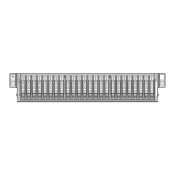
Chapter 1: Introduction Front Features The SC227TS-R2K05P3 is a 2U chassis See the illustration below for the features included on the front of the chassis. Figure 1-2. Chassis Front View Front Chassis Features Item Feature Description Control Panel Control panel for the server. See Section 1.4 for details. Hard Drive Carriers Hot-swap hard drive carriers for front mounted hot-swap NVMe drives Rear Features... -
Page 12: Motherboard Layout
SuperStorage Server 2029P-DN2R24L User's Manual 1.5 Motherboard Layout Below is a layout of the X11DSN-TS with jumper, connector and LED locations shown. See the table on the following page for descriptions. For detailed descriptions, pinout information and jumper settings, refer to Chapter 4. USB0/1(3.0) IPMI_LAN LAN1... -
Page 13: Quick Reference Table
M.2-P PCI-E M.2 slot S-SATA 3.0 connection ports 0/1 supported by the Intel SCU. These S-SATA ports have power pins S-SATA0/S-SATA1 built-in and support Supermicro SuperDOM (Disk On Module) devices SIOM1 PCI-E 3.0 x8 (x16) slot supported by CPU2 USB0/1 Back panel USB 3.0 ports... - Page 14 SuperStorage Server 2029P-DN2R24L User's Manual #F-0 #M-0 #E-0 #L-0 #D-0 #K-0 X11DSN-TS #C-0 #J-0 #B-0 #H-0 #A-0 #G-0 DDR4 DDR4 #2B #2A PCI-E X16 G3 Slot#1 LWIO Riser PCI-E X16 G3 (LANE REVERSE) Slot#2 PCI-E X16 G3 PCI-E X16 G3 NTB X8 G3 PCI-E X8 G3 SIOM...
-
Page 15: Chapter 2 Server Installation
Chapter 2: Server Installation Chapter 2 Server Installation 2.1 Overview This chapter provides advice and instructions for mounting your system in a server rack. If your system is not already fully integrated with processors, system memory etc., refer to Chapter 4 for details on installing those specific components. Caution: Electrostatic Discharge (ESD) can damage electronic components. -
Page 16: Server Precautions
SuperStorage Server 2029P-DN2R24L User's Manual • You should extend only one server or component at a time - extending two or more simul- taneously may cause the rack to become unstable. Server Precautions • Review the electrical and general safety precautions in Appendix B. •... -
Page 17: Circuit Overloading
Chapter 2: Server Installation Circuit Overloading Consideration should be given to the connection of the equipment to the power supply circuitry and the effect that any possible overloading of circuits might have on overcurrent protection and power supply wiring. Appropriate consideration of equipment nameplate ratings should be used when addressing this concern. -
Page 18: Installing The Rails
SuperStorage Server 2029P-DN2R24L User's Manual 2.3 Installing the Rails There are a variety of rack units on the market, which may require a slightly different assembly procedure. The following is a basic guideline for installing the system into a rack with the rack mounting hardware provided. -
Page 19: Releasing The Inner Rail
Chapter 2: Server Installation Slide rail mounted equipment is not to be used as a shelf or a work space. Warning: do not pick up the server with the front handles. They are designed to pull the system from a rack only. Releasing the Inner Rail It is necessary to release the inner rail from the middle and outer rails before installing the inner rail on the chassis. -
Page 20: Installing The Inner Rails On The Chassis
SuperStorage Server 2029P-DN2R24L User's Manual Installing The Inner Rails on the Chassis Installing the Inner Rails 1. Confirm that the left and right inner rails have been correctly identified. 2. Place the inner rail firmly against the side of the chassis, aligning the pins on the side of the chassis with the slotted thru holes in the inner rail. - Page 21 Chapter 2: Server Installation 1. Installing the outer rails on the rack 2. Installing the outer rails 3. Confirm that the left and right outer rails have been correctly identified. 4. Release the small locking lever on the inside of the middle rail and push the middle rail back into the outer rail.
-
Page 22: Installing Into The Rack
SuperStorage Server 2029P-DN2R24L User's Manual Installing into the Rack After the rails are installed on the chassis and on the rack, the server can be installed in the rack. It is heavy and requires two to three people to lift. Installing the Chassis into a Rack 1. -
Page 23: Removing The Chassis From The Rack
Chapter 2: Server Installation Removing the Chassis From the Rack Caution: The server is heavy and requires two to three people to lift it out. Removing the Chassis 1. Lift the right and left front latches which are just below the LED control panels on the front edges of the chassis. -
Page 24: Removing The Outer Rails From The Rack
Note: You have received a different outer rail than the one pictured, This rail features a side release latch on the front of the outer rail, which opens inward to release the outer rail from the rack. Contact Supermicro's Technical Support department if you need additional assistance. -
Page 25: Chapter 3 Maintenance And Component Installation
SuperStorage Server 2029P-DN2R24L User's Manual Chapter 3 Maintenance and Component Installation This chapter provides instructions on installing and replacing main system components. To prevent compatibility issues, only use components that match the specifications and/or part numbers given. Installation or replacement of most components require that power first be removed from the system. - Page 26 Chapter 3: Maintenance and Component Installation Remove Screw Remove Screw Figure 3-1. Removing the Mid-chassis Cover...
-
Page 27: Rear Cover
SuperStorage Server 2029P-DN2R24L User's Manual Rear Cover Removing the Rear Cover 1. Power down the system and remove the power cords from the rear of the power supplies as described in Section 3-1. 2. Remove the front cover as described in Section 3-2. 3. -
Page 28: Motherboard Components
Check that the plastic socket dust cover is in place and none of the socket pins are bent— otherwise, contact your retailer. • Refer to the Supermicro website for updates on CPU support. • Graphics in this manual are for illustration. Your components may look slightly different. -
Page 29: Assembling The Processor Package
SuperStorage Server 2029P-DN2R24L User's Manual Assembling the Processor Package Attach the processor to the thin processor clip to create the processor package. 1. On the top corner of the CPU, locate pin 1 (A), marked by a triangle. Also, locate notch B and notch C (and notch D for F models) on the CPU as shown below. - Page 30 Chapter 3: Maintenance and Component Installation CPU (Upside Down) Align Notch D of the CPU w/CPU LGA Lands up and Notch D of the Processor Clip Align Notch C of the CPU Pin 1 and Notch C of the Processor Clip Align Notch B of the CPU and Notch B of the Processor Clip CPU/Heatsink Package...
- Page 31 SuperStorage Server 2029P-DN2R24L User's Manual After creating the processor package assembly, mount it onto the heatsink to create the processor heatsink module (PHM). 1. On the heatsink label, locate "1" and the corner next to it. Turn the heatsink upside down with the thermal grease side facing up, keeping track of the "1"...
-
Page 32: Removing The Dust Cover From The Cpu Socket
Chapter 3: Maintenance and Component Installation Removing the Dust Cover from the CPU Socket Remove the dust cover from the CPU socket, exposing the socket pins as shown below. Caution: Do not touch the socket pins. Dust Cover Remove the dust cover from the CPU socket. -
Page 33: Installing The Processor Heatsink Module (Phm)
SuperStorage Server 2029P-DN2R24L User's Manual Installing the Processor Heatsink Module (PHM) 1. Locate the triangle (pin 1) on the CPU socket. Also locate the pin 1 corner of the PHM that is closest to "1" on the heatsink label. To confirm, look at the underside of the PHM and note the hollow triangle in the processor clip and printed triangle on the CPU located next to a screw at the corner. -
Page 34: Removing The Processor Heatsink Module From The Motherboard
Chapter 3: Maintenance and Component Installation Removing the Processor Heatsink Module from the Motherboard Before removing the processor heatsink module (PHM), power down as described in Section 3.1. 1. Using a T30 Torx-bit screwdriver, loosen and remove the screws on the PHM from the socket, starting with the screw marked #4, in the sequence of 4, 3, 2, 1. -
Page 35: Memory Support And Installation
SuperStorage Server 2029P-DN2R24L User's Manual 3.4 Memory Support and Installation Note: Check the Supermicro website for recommended memory modules. Important: Exercise extreme care when installing or removing DIMM modules to prevent any damage. This document provides the user with an easy-to-use guide for proper memory configuration... -
Page 36: Memory Installation Sequence
Chapter 3: Maintenance and Component Installation Note: 2933 MHz memory is supported by the 82xx/62xx series processors only. DDR4 Memory Support for 81xx/61xx/51xx/41xx/31xx Processors Speed (MT/s) Ranks DIMM Capacity (GB) One Slot Two Slots per Channel per Channel DIMM Type One DIMM One DIMM Two DIMMs... -
Page 37: General Memory Population Requirements
SuperStorage Server 2029P-DN2R24L User's Manual General Memory Population Requirements 1. Be sure to use the memory modules of the same type and speed on the motherboard. Mixing of memory modules of different types and speeds is not allowed. 2. Using unbalanced memory topology such as populating two DIMMs in one channel while populating one DIMM in another channel on the same motherboard will result in reduced memory performance. - Page 38 Chapter 3: Maintenance and Component Installation Note: Unbalanced memory configuration decreases memory performance and is not recommended for Supermicro motherboards. Memory Population Tables for X11DP Motherboards w/12 DIMM Slots CPUs/DIMMs Memory Population Sequence 1 CPU & 1 DIMM CPU1: P1-DIMMA1 1 CPU &...
- Page 39 SuperStorage Server 2029P-DN2R24L User's Manual DIMM Installation 1. Insert the desired number of DIMMs into the memory slots, starting with P1-DIMM A1. For the system to work properly, please use memory modules of the same type and speed on the motherboard. BIOS X11DPU-V DESIGNED IN USA...
-
Page 40: Motherboard Battery
Chapter 3: Maintenance and Component Installation Motherboard Battery The motherboard uses non-volatile memory to retain system information when system power is removed. This memory is powered by a lithium battery residing on the motherboard. Replacing the Battery Begin by removing power from the system as described in section 3.1. 1. -
Page 41: Chassis Components
SuperStorage Server 2029P-DN2R24L User's Manual 3.5 Chassis Components Installing Hard Drives The SC227TS comes equipped with 24 2.5" hot-swappable hard drives. These drives can be removed without powering down the system. Only enterprise level NVMe drives are supported. Removing Hard Drive Carriers from the Chassis 1. - Page 42 Chapter 3: Maintenance and Component Installation Installing a Hard Drive into a Drive Carrier 1. Remove the dummy drive, which comes pre-installed in the drive carrier, by removing the screws securing the dummy drive to the carrier. Note that these screws cannot be reused on the actual 2.5"...
-
Page 43: Drive Carrier Leds
SuperStorage Server 2029P-DN2R24L User's Manual Drive Carrier LEDs The chassis includes externally accessible NVMe drives. Each drive carrier displays two status LEDs on the front of the carrier. LED Color State Status Activity LED Blue Solid On NVMe drive installed Blue Blinking I/O activity... -
Page 44: Removing The Motherboard Modules
Chapter 3: Maintenance and Component Installation Removing the Motherboard Modules The SC227TS features a removable motherboard module that allows easy access to the motherboard. Removing the Motherboard Module 1. Power down the system and remove the power cords from the rear of the power supplies as described in Section 3-1. -
Page 45: Installing The Expansion Cards
SuperStorage Server 2029P-DN2R24L User's Manual Installing the Expansion Cards The SC227TS provides two PCI slots for low-profile expansion cards. Note that the motherboard must be installed prior to the installation of the expansion cards. Installing Expansion Cards Installing an Expansion Cards 1. -
Page 46: Changing The Power Supplies
Chapter 3: Maintenance and Component Installation Changing the Power Supplies The SC227TS chassis has two redundant power supplies. The power modules are hot- swappable, enabling the power supplies to be changed without powering down the system. These power supplies are auto-switching capable. This enables the power supply to automatically sense and operate at a 100v to 240v input voltage. -
Page 47: Power Distributor Board
SuperStorage Server 2029P-DN2R24L User's Manual Power Distributor Board The SC227TS chassis requires two power distributor boards. These boards are located behind the power supplies and are separated with a set of spacers. In the unlikely event that a board needs to be replaced, use the following instructions. Changing the Power Distributor Board 1. -
Page 48: System Fans
SuperStorage Server 2029P-DN2R24L User's Manual System Fans Five heavy-duty fans provide cooling for the chassis. These fans circulate air through the chassis as a means of lowering the chassis internal temperature. The SC227TS fans are hot-swappable, enabling the fans to be replaced without powering down the system. Fan speed is controlled by system temperature via BMC. -
Page 49: Removing And Installing The Backplanes
Chapter 3: Maintenance and Component Installation Removing and Installing the Backplanes The SC227TS chassis features a single backplane in the chassis. Removing the Backplane Removing the First Backplane from the Front Compartment 1. Power down the system and remove the power cords as described in Section 3-1 and open the chassis covers as described in Section 3-2. -
Page 50: Installing The Backplane
SuperStorage Server 2029P-DN2R24L User's Manual Installing the Backplane Installing the Backplane Into the Chassis 1. Power down the system and remove the power cords as described in Section 3-1. Open the chassis covers as described in Section 3-2. 2. Ensure that all of the hard drives have been removed from the hard drive bays. 3. -
Page 51: Removing And Installing The Midplane
Chapter 3: Maintenance and Component Installation Removing and Installing the Midplane Removing the Midplane Removing the Midplane from the Chassis 1. Power down the system as described in Section 3-1 and open the chassis covers as described in Section 3-2. 2. -
Page 52: Installing The Midplane
SuperStorage Server 2029P-DN2R24L User's Manual Installing the Midplane Installing the Midplane Into the Chassis 1. Power down the system as described in Section 3-1 and open the chassis covers as described in Section 3-2. 2. Put the midplane into the midplane bracket, aligning the holes in the midplane with those in the bracket. -
Page 53: Chapter 4 Motherboard Connections
Tachometer PWM Control Super I/O Module (SIOM) A Supermicro proprietary Super I/O module is located at JSIOM1. This I/O module supports a PCI-E 3.0 x16 add-on card on the X11DSN-TS. TPM Header The JTPM1 header is used to connect a Trusted Platform Module TPM/Port 80, which is available from a third-party vendor. - Page 54 These two S-SATA ports have power pins built in and can be used with Supermicro SuperDOMs which do not need external power cable support. Supermicro SuperDOMs are backward-compatible with regular SATA HDDs or SATA DOMs that need external power cables.
-
Page 55: Ports
SuperStorage Server 2029P-DN2R24L User's Manual 4.2 Ports Rear I/O Ports See Figure 4-1 below for the locations and descriptions of the various I/O ports on the rear of the motherboard. SAN MAC X11DSN-TS MAC CODE Rev. 1.00 IPMI CODE BIOS BAR CODE LICENSE Figure 4-1. - Page 56 Chapter 4: Motherboard Connections Universal Serial Bus (USB) Ports There are two USB 3.0 port (USB 0/1) on the I/O back panel, and a Type A USB 3.0 header (USB 2) on the motherboard to provide front access USB connection. The onboard headers can be used to provide front side USB access with a cable (not included).
-
Page 57: Jumpers
SuperStorage Server 2029P-DN2R24L User's Manual 4.3 Jumpers Explanation of Jumpers To modify the operation of the motherboard, jumpers are used to choose between optional settings. Jumpers create shorts between two pins to change the function associated with it. Pin 1 is identified with a square solder pad on the printed circuit board. See the motherboard layout page for jumper locations. - Page 58 Chapter 4: Motherboard Connections VGA Enable/Disable JPG1 allows you to enable or disable the VGA port. The default setting is Enabled. VGA Enable/Disable Jumper Settings Jumper Setting Definition Pins 1-2 Enabled Pins 2-3 Disabled Manufacturing Mode Select (ME Select) Close JPME2 to bypass SPI flash security and force the system to use the Manufacturing Mode, which will allow you to flash the system firmware from a host server to modify system settings.
-
Page 59: Led Indicators
SuperStorage Server 2029P-DN2R24L User's Manual NTB Enable Use Jumper (JPX) to enable or disable onboard Non-Transparent Bridge (NTB) support. The default setting is Enabled. NTB Enable Jumper Settings Jumper Setting Definition Pins 1-2 Enabled Pins 2-3 Disabled 4.4 LED Indicators LAN LEDs The LAN ports are located on the I/O Backplane on the motherboard. - Page 60 Chapter 4: Motherboard Connections System Heartbeat LED LEDL (the bottom LED indicator) on the I/O back panel is used as the system heartbeat LED. When the LED is blinking, your system functions normally. See the table below for the LED status. System Heartbeat LED Indicator LED State Definition...
-
Page 61: Chapter 5 Software
USB/SATA DVD drive, or a USB flash drive, or the IPMI KVM console. 2. Retrieve the proper RST/RSTe driver. Go to the Supermicro web page for your motherboard and click on "Download the Latest Drivers and Utilities", select the proper driver, and copy it to a USB flash drive. - Page 62 Chapter 5: Software 4. During Windows Setup, continue to the dialog where you select the drives on which to install Windows. If the disk you want to use is not listed, click on “Load driver” link at the bottom left corner. Figure 5-2.
-
Page 63: Driver Installation
The Supermicro website contains drivers and utilities for your system at https://www. supermicro.com/wdl/driver. Some of these must be installed, such as the chipset driver. After accessing the website, go into the CDR_Images (in the parent directory of the above link) and locate the ISO file for your motherboard. Download this file to to a USB flash drive or a DVD. -
Page 64: Superdoctor ® 5
5.3 SuperDoctor ® The Supermicro SuperDoctor 5 is a program that functions in a command-line or web-based interface for Windows and Linux operating systems. The program monitors such system health information as CPU temperature, system voltages, system power consumption, fan speed, and provides alerts via email or Simple Network Management Protocol (SNMP). -
Page 65: Chapter 6 Uefi Bios
SuperStorage Server 2029P-DN2R24L User's Manual Chapter 6 UEFI BIOS 6.1 Introduction This chapter describes the AMIBIOS™ Setup utility for the X11DSN-TS motherboard(s). The BIOS is stored in a flash chip and can be easily upgraded. Note: Due to periodic changes to the BIOS, some settings may have been added or deleted and might not yet be recorded in this manual. -
Page 66: Main Menu
Note: The time is in the 24-hour format. For example, 5:30 P.M. appears as 17:30:00. The date's default value is 01/01/2014 after RTC reset. Supermicro X11DSN-TS BIOS Version This item displays the version of the BIOS ROM used in the system. -
Page 67: Advanced Settings Menu
SuperStorage Server 2029P-DN2R24L User's Manual CPLD Version This item displays the version of the CPLD (Complex-Programmable Logical Device) used in the system. Memory Information Total Memory This item displays the total size of memory available in the system. 6.3 Advanced Settings Menu Use the arrow keys to select the Advanced submenu and press <Enter>... - Page 68 Chapter 6: UEFI BIOS Boot Feature Quiet Boot Use this feature to select the screen between displaying POST messages or the OEM logo at bootup. Select Disabled to display the POST messages. Select Enabled to display the OEM logo instead of the normal POST messages. The options are Enabled and Disabled. Note: POST message is always displayed regardless of the item setting.
- Page 69 SuperStorage Server 2029P-DN2R24L User's Manual Power Configuration Watch Dog Function Select Enabled to allow the Watch Dog timer to reboot the system when it is inactive for more than 5 minutes. The options are Enabled and Disabled. Restore on AC Power Loss Use this feature to set the power state after a power outage.
- Page 70 Chapter 6: UEFI BIOS • Processor Min Ratio • Microcode Revision • L1 Cache RAM • L2 Cache RAM • L3 Cache RAM • Processor 0 Version/Processor 1 Version Hyper-Threading (ALL) Select Enable to use Intel Hyper-Threading Technology to enhance CPU performance. The options are Enable and Disable.
- Page 71 SuperStorage Server 2029P-DN2R24L User's Manual DCU (Data Cache Unit) Streamer Prefetcher (Available when supported by the CPU) If this feature is set to Enable, the DCU (Data Cache Unit) streamer prefetcher will prefetch data streams from the cache memory to the DCU (Data Cache Unit) to speed up data accessing and processing for CPU performance enhancement.
- Page 72 Chapter 6: UEFI BIOS Energy Performance BIAS Setting (Available when "Power Performance Tuning" is set to BIOS Controls EPB) Use this feature to set the processor power use policy to achieve the desired operation settings for your machine by prioritizing system performance or energy savings. Select Maximum Performance to maximize system performance (to its highest potential);...
- Page 73 SuperStorage Server 2029P-DN2R24L User's Manual CPU C State Control Autonomous Core C-State Select Enable to support Autonomous Core C-State control which will allow the processor core to control its C-State setting automatically and independently. The options are Enable and Disable. CPU C6 Report Select Enable to allow the BIOS to report the CPU C6 state (ACPI C3) to the operating system.
- Page 74 Chapter 6: UEFI BIOS Chipset Configuration North Bridge This feature allows the user to configure the settings for the Intel North Bridge. UPI (Ultra Path Interconnect) General Configuration This section displays the following UPI General Configuration information: •...
- Page 75 SuperStorage Server 2029P-DN2R24L User's Manual SNC (Sub NUMA Cluster) Select Enable for Sub-NUMA (Non-uniform memory access) Cluster support. Select Auto for 1-cluster or 2-cluster support depending on the satuts of IMC (Integrated Memory Controller) Interleaving. The options are Disable, Enable, and Auto. XPT Prefetch Select Enable for Extended (Xtended) Prediction Table (XPT) Prefetch support which will allow a read request to be sent to the memory controller requesting the prefetch in parallel...
- Page 76 Chapter 6: UEFI BIOS Data Scrambling for NVDIMM Select Enable to enable data scrambling for onboard NVDIMM memory to enhance system performance and security. The options are Auto, Disable, and Enable. Data Scrambling for DDR4 Select Enable to enable data scrambling for DDR4 memory to enhance system performance and security.
- Page 77 SuperStorage Server 2029P-DN2R24L User's Manual Memory RAS (Reliability_Availability_Serviceability) Configuration Use this submenu to configure the following Memory RAS settings. Static Virtual Lockstep Mode Select Enable to support the Static Virtual Lockstep mode to enhance memory performance. The options are Enable and Disable. Mirror Mode Use this feature to configure the mirror mode settings for all 1LM/2LM memory modules installed in the system which will create a duplicate copy of data stored in the memory to...
- Page 78 Chapter 6: UEFI BIOS ADDDC (Adaptive Double Device Data Correction) Sparing Select Enable for Adaptive Double Device Data Correction (ADDDC) support, which will not only provide memory error checking and correction but will also prevent the system from issuing a performance penalty before a device fails. Please note that virtual lockstep mode will only start to work for ADDDC after a faulty DRAM module is spared.
- Page 79 SuperStorage Server 2029P-DN2R24L User's Manual MCP1 (IIO PCIe Br5) This feature configures the PCI-E Bifuraction setting for a PCI-E port specified by the user. The options are x16 and Auto. CPU1 PCI-E Br0D00F0 - Port 0/DMI (Available for CPU 1 Configuration only) Link Speed This feature configures the link speed of a PCI-E port specified by the user.
- Page 80 Chapter 6: UEFI BIOS Intel® VT for Directed I/O (VT-d) Intel® VT for Directed I/O (VT-d) Select Enable to use Intel Virtualization Technology support for Direct I/O VT-d by reporting the I/O device assignments to the VMM (Virtual Machine Monitor) through the DMAR ACPI tables.
- Page 81 SuperStorage Server 2029P-DN2R24L User's Manual *If the item "Intel VMD for Volume Management Device" above is set to Enable, the following items will be dislayed: VMD port 1A~VMD port 1D (Available when the device is detected by the system) Select Enable to use the Intel Volume Management Device Technology for this specific root port.
- Page 82 Chapter 6: UEFI BIOS Intel® VMD for Volume Management Device on CPU2 VMD Config for PStack0 Intel® VMD for Volume Management Device Select Enable to use the Intel Volume Management Device Technology for this stack. The options are Disable and Enable. *If the item "Intel VMD for Volume Management Device"...
- Page 83 SuperStorage Server 2029P-DN2R24L User's Manual Hot Plug Capable (Available when the device is detected by the system) Use this feature to enable hot plug support for PCI-E root ports 3A~3D. The options are Disable and Enable. II0-PCI-E Express Global Options PCI-E Completion Timeout Disable Use this feature to enable PCI-E Completion Timeout support for electric tuning.
- Page 84 Chapter 6: UEFI BIOS Server ME (Management Engine) Configuration This feature displays the following system ME configuration settings. • General ME Configuration • Operational Firmware Version • Backup Firmware Version • Recovery Firmware Version • ME Firmware Status #1/ME Firmware Status #2 •...
- Page 85 SuperStorage Server 2029P-DN2R24L User's Manual (I-)SATA Port 0 - SATA Port 7 Hot Plug Select Enable to support Hot-plugging for the device installed on a selected SATA port which will allow the user to replace the device installed in the slot without shutting down the system.
- Page 86 Chapter 6: UEFI BIOS sSATA Port 0 - sSATA Port 5 Hot Plug Select Enable to support Hot-plugging for the device installed on an sSATA port selected by the user which will allow the user to replace the device installed in the slot without shutting down the system.
- Page 87 SuperStorage Server 2029P-DN2R24L User's Manual MMCFG Base This feature determines the lowest MMCFG (Memory-Mapped Configuration) base assigned to PCI devices. The options are 1G, 1.5G, 1.75G. 2G, 2.25G, and 3G. NVMe Firmware Source This feature determines which type of the NVMe firmware should be used in your system. The options are Vendor Defined Firmware and AMI Native Support.
- Page 88 Chapter 6: UEFI BIOS Network Stack Configuration Network Stack Select Enabled to enable PXE (Preboot Execution Environment) or UEFI (Unified Extensible Firmware Interface) for network stack support. The options are Enabled and Disabled. *If "Network Stack" is set to Enabled, the following items will display: Ipv4 PXE Support Select Enabled to enable Ipv4 PXE boot support.
- Page 89 SuperStorage Server 2029P-DN2R24L User's Manual Device Settings This feature displays the base I/O port address and the Interrupt Request address of a serial port specified by the user. Note: This item is hidden when Serial Port 1 is set to Disabled. Change Settings This feature specifies the base I/O port address and the Interrupt Request address of Serial Port 1.
- Page 90 Chapter 6: UEFI BIOS *If the item above set to Enabled, the following items will become available for configuration: Console Redirection Settings (when COM1 Console Redirection is Enabled) Terminal Type Use this feature to select the target terminal emulation type for Console Redirection. Select VT100 to use the ASCII Character set.
- Page 91 SuperStorage Server 2029P-DN2R24L User's Manual Recorder Mode Select Enabled to capture the data displayed on a terminal and send it as text messages to a remote server. The options are Disabled and Enabled. Resolution 100x31 Select Enabled for extended-terminal resolution support. The options are Disabled and Enabled.
- Page 92 Chapter 6: UEFI BIOS Bits Per second Use this feature to set the transmission speed for a serial port used in Console Redirection. Make sure that the same speed is used in the host computer and the client computer. A lower transmission speed may be required for long and busy lines.
- Page 93 SuperStorage Server 2029P-DN2R24L User's Manual Putty KeyPad This feature selects Function Keys and KeyPad settings for Putty, which is a terminal emulator designed for the Windows OS. The options are VT100, LINUX, XTERMR6, SCO, ESCN, and VT400. Redirection After BIOS Post Use this feature to enable or disable legacy Console Redirection after BIOS POST (Power-On Self-Test).
- Page 94 Chapter 6: UEFI BIOS Bits Per Second This feature sets the transmission speed for a serial port used in Console Redirection. Make sure that the same speed is used in both host computer and the client computer. A lower transmission speed may be required for long and busy lines. The options are 9600, 19200, 57600, and 115200 (bits per second).
- Page 95 SuperStorage Server 2029P-DN2R24L User's Manual Trusted Computing (Available when a TPM device is detected and PTT Support under "Server ME Config" is not Enabled) When a TPM (Trusted-Platform Module) device is detected in your machine, the following information will display. •...
- Page 96 Chapter 6: UEFI BIOS Pending Operation Use this feature to schedule a TPM-related operation to be performed by a security (TPM) device at the next system boot to enhance system data integrity. Your system will reboot to carry out a pending TPM operation. The options are None and TPM Clear. Note: Your system will reboot to carry out a pending TPM operation.
- Page 97 SuperStorage Server 2029P-DN2R24L User's Manual Note 2: For more information on TPM, please refer to the TPM manual at http://www. supermicro.com/manuals/other. iSCSI Configuration iSCSI Initiator Name This feature allows the user to enter the unique name of the iSCSI Initiator in IQN format.
-
Page 98: Event Logs
Chapter 6: UEFI BIOS 6.4 Event Logs Use this feature to configure Event Log settings. Change SMBIOS Event Log Settings Enabling/Disabling Options SMBIOS Event Log Select Enabled to enable SMBIOS (System Management BIOS) Event Logging during system boot. The options are Enabled and Disabled. Erasing Settings Erase Event Log Select Enabled to erase all error events in the SMBIOS (System Management BIOS) log... - Page 99 SuperStorage Server 2029P-DN2R24L User's Manual When Log is Full Select Erase Immediately to immediately erase all errors in the SMBIOS event log when the event log is full. Select Do Nothing for the system to do nothing when the SMBIOS event log is full.
-
Page 100: Ipmi
Chapter 6: UEFI BIOS 6.5 IPMI Use this feature to configure Intelligent Platform Management Interface (IPMI) settings. When you select this submenu and press the <Enter> key, the following information will display: • BMC Firmware Revision: This feature indicates the firmware revision of the BMC (Base- board Management Controller) used in your system. - Page 101 SuperStorage Server 2029P-DN2R24L User's Manual Erasing Settings Erase SEL Select Yes, On next reset to erase all system event logs upon next system reboot. Select Yes, On every reset to erase all system event logs upon each system reboot. Select No to keep all system event logs after each system reboot.
- Page 102 Chapter 6: UEFI BIOS *If the item "Update IPMI LAN Configuration" is set to Yes, the following items will display: IPMI LAN Selection Use this feature to select the type of the IPMI LAN. The options are Dedicated, Shared, and Failover. Configuration Address Source Use this feature to select the IP address source for this computer.
-
Page 103: Security Settings
SuperStorage Server 2029P-DN2R24L User's Manual 6.6 Security Settings This menu allows the user to configure the following security settings for the system. Administrator Password Use this feature to set the administrator password which is required to enter the BIOS setup utility. - Page 104 Chapter 6: UEFI BIOS Secure Boot When you select this submenu and press the <Enter> key, the following items will display: • System Mode • Secure Boot Secure Boot If this feature is set to Enabled, Secure Boot will be activated when a Platform Key (PK) is entered.
- Page 105 SuperStorage Server 2029P-DN2R24L User's Manual Platform Key (PK) This feature allows the user to enter and configure a set of values to be used as a platform firmware key for the system. This set of values also indicate the size, the keys numbers, and the key source of the Platform Key.
-
Page 106: Boot Settings
Chapter 6: UEFI BIOS 6.7 Boot Settings Use this feature to configure Boot Settings: Boot Mode Select Use this feature to select the type of devices to be used for system boot. The options are Legacy, UEFI (Unified Extensible Firmware Interface), and Dual. Legacy to EFI Support Select Enabled for the system to boot from an EFI OS when the Legacy OS fails. - Page 107 SuperStorage Server 2029P-DN2R24L User's Manual *When the item above -"Boot Mode Select" is set to Legacy, the following items will be display for configuration: • Boot Option #1 - Boot Option #8 *When the item above -"Boot Mode Select" is set to UEFI, the following items will be display for configuration: •...
- Page 108 Chapter 6: UEFI BIOS Delete Boot Option Use this feature to select a boot device to delete from the boot priority list. Delete Boot Option Use this feature to remove an EFI boot option from the boot priority list. ...
-
Page 109: Save & Exit
SuperStorage Server 2029P-DN2R24L User's Manual 6.8 Save & Exit Select the Save & Exit tab from the BIOS setup screen to configure the settings below. Save Options Discard Changes and Exit Select this option to quit the BIOS setup without making any permanent changes to the system configuration and reboot the computer. - Page 110 Chapter 6: UEFI BIOS Discard Changes Select this option and press <Enter> to discard all the changes and return to the AMI BIOS setup utility. Default Options Restore Optimized Defaults To set this feature, select Restore Defaults from the Exit menu and press <Enter> to load manufacturer default settings which are intended for maximum system performance but not for maximum stability.
-
Page 111: Appendix A Bios Error Codes
SuperStorage Server 2029P-DN2R24L User's Manual Appendix A BIOS Error Codes A.1 BIOS Error Beep (POST) Codes During the POST (Power-On Self-Test) routines, which are performed each time the system is powered on, errors may occur. Non-fatal errors are those which, in most cases, allow the system to continue the boot-up process. - Page 112 When BIOS performs the Power On Self Test, it writes checkpoint codes to I/O port 0080h. If the computer cannot complete the boot process, a diagnostic card can be attached to the computer to read I/O port 0080h (Supermicro p/n AOC-LPC80-20). For information on AMI updates, please refer to http://www.ami.com/products/.
-
Page 113: Appendix B Standardized Warning Statements For Ac Systems
Supermicro's Technical Support department for assistance. Only certified technicians should attempt to install or configure components. Read this appendix in its entirety before installing or configuring components in the Supermicro chassis. These warnings may also be found on our website at http://www.supermicro.com/about/... - Page 114 Appendix B: Standardized Warning Statements Warnung WICHTIGE SICHERHEITSHINWEISE Dieses Warnsymbol bedeutet Gefahr. Sie befinden sich in einer Situation, die zu Verletzungen führen kann. Machen Sie sich vor der Arbeit mit Geräten mit den Gefahren elektrischer Schaltungen und den üblichen Verfahren zur Vorbeugung vor Unfällen vertraut. Suchen Sie mit der am Ende jeder Warnung angegebenen Anweisungsnummer nach der jeweiligen Übersetzung in den übersetzten Sicherheitshinweisen, die zusammen mit diesem Gerät ausgeliefert wurden.
- Page 115 SuperStorage Server 2029P-DN2R24L User's Manual . ٌ ا ك ً ف حالة و ٌ يك أى تتسبب ف اصابة جسذ ة ٌ هذا الزهز ع ٌ خطز !تحذ ز قبل أى تعول عىل أي هعذات،يك عىل علن بالوخاطز ال ا ٌجوة عي الذوائز ٍ...
- Page 116 Appendix B: Standardized Warning Statements Warnung Vor dem Anschließen des Systems an die Stromquelle die Installationsanweisungen lesen. ¡Advertencia! Lea las instrucciones de instalación antes de conectar el sistema a la red de alimentación. Attention Avant de brancher le système sur la source d'alimentation, consulter les directives d'installation. .יש...
- Page 117 SuperStorage Server 2029P-DN2R24L User's Manual Warnung Dieses Produkt ist darauf angewiesen, dass im Gebäude ein Kurzschluss- bzw. Überstromschutz installiert ist. Stellen Sie sicher, dass der Nennwert der Schutzvorrichtung nicht mehr als: 250 V, 20 A beträgt. ¡Advertencia! Este equipo utiliza el sistema de protección contra cortocircuitos (o sobrecorrientes) del edificio.
- Page 118 Appendix B: Standardized Warning Statements Power Disconnection Warning Warning! The system must be disconnected from all sources of power and the power cord removed from the power supply module(s) before accessing the chassis interior to install or remove system components. 電源切断の警告...
- Page 119 SuperStorage Server 2029P-DN2R24L User's Manual يجب فصم اننظاو من جميع مصادر انطاقت وإ ز انت سهك انكهرباء من وحدة امداد انطاقت قبم انىصىل إىن امنناطق انداخهيت نههيكم نتثبيج أو إ ز انت مكىناث الجهاز 경고! 시스템에 부품들을 장착하거나 제거하기 위해서는 섀시 내부에 접근하기 전에 반드시 전원 공급장치로부터...
- Page 120 Appendix B: Standardized Warning Statements Attention Il est vivement recommandé de confier l'installation, le remplacement et la maintenance de ces équipements à des personnels qualifiés et expérimentés. !אזהרה .צוות מוסמך בלבד רשאי להתקין, להחליף את הציוד או לתת שירות עבור הציוד واملدربيه...
- Page 121 SuperStorage Server 2029P-DN2R24L User's Manual Warnung Diese Einheit ist zur Installation in Bereichen mit beschränktem Zutritt vorgesehen. Der Zutritt zu derartigen Bereichen ist nur mit einem Spezialwerkzeug, Schloss und Schlüssel oder einer sonstigen Sicherheitsvorkehrung möglich. ¡Advertencia! Esta unidad ha sido diseñada para instalación en áreas de acceso restringido. Sólo puede obtenerse acceso a una de estas áreas mediante la utilización de una herramienta especial, cerradura con llave u otro medio de seguridad.
- Page 122 Appendix B: Standardized Warning Statements Battery Handling Warning! There is the danger of explosion if the battery is replaced incorrectly. Replace the battery only with the same or equivalent type recommended by the manufacturer. Dispose of used batteries according to the manufacturer's instructions 電池の取り扱い...
- Page 123 SuperStorage Server 2029P-DN2R24L User's Manual هناك خطر من انفجار يف حالة اسحبذال البطارية بطريقة غري صحيحة فعليل اسحبذال البطارية فقط بنفس النىع أو ما يعادلها مام أوصث به الرشمة املصنعة جخلص من البطاريات املسحعملة وفقا لحعليامت الرشمة الصانعة 경고! 배터리가 올바르게 교체되지 않으면 폭발의 위험이 있습니다. 기존 배터리와 동일하거나 제 조사에서...
- Page 124 Appendix B: Standardized Warning Statements ¡Advertencia! Puede que esta unidad tenga más de una conexión para fuentes de alimentación. Para cortar por completo el suministro de energía, deben desconectarse todas las conexiones. Attention Cette unité peut avoir plus d'une connexion d'alimentation. Pour supprimer toute tension et tout courant électrique de l'unité, toutes les connexions d'alimentation doivent être débranchées.
- Page 125 SuperStorage Server 2029P-DN2R24L User's Manual Backplane Voltage Warning! Hazardous voltage or energy is present on the backplane when the system is operating. Use caution when servicing. バックプレーンの電圧 システムの稼働中は危険な電圧または電力が、 バックプレーン上にかかっています。 修理する際には注意く ださい。 警告 当系统正在进行时,背板上有很危险的电压或能量,进行维修时务必小心。 警告 當系統正在進行時,背板上有危險的電壓或能量,進行維修時務必小心。 Warnung Wenn das System in Betrieb ist, treten auf der Rückwandplatine gefährliche Spannungen oder Energien auf.
- Page 126 Appendix B: Standardized Warning Statements هناك خطز مه التيار الكهزبايئ أوالطاقة املىجىدة عىل اللىحة عندما يكىن النظام يعمل كه حذ ر ا عند خدمة هذا الجهاس 경고! 시스템이 동작 중일 때 후면판 (Backplane)에는 위험한 전압이나 에너지가 발생 합니다. 서비스 작업 시 주의하십시오. Waarschuwing Een gevaarlijke spanning of energie is aanwezig op de backplane wanneer het systeem in gebruik is.
- Page 127 SuperStorage Server 2029P-DN2R24L User's Manual תיאום חוקי החשמל הארצי !אזהרה .התקנת הציוד חייבת להיות תואמת לחוקי החשמל המקומיים והארציים تركيب املعدات الكهربائية يجب أن ميتثل للقىاويه املحلية والىطىية املتعلقة بالكهرباء 경고! 현 지역 및 국가의 전기 규정에 따라 장비를 설치해야 합니다. Waarschuwing Bij installatie van de apparatuur moet worden voldaan aan de lokale en nationale elektriciteitsvoorschriften.
- Page 128 Appendix B: Standardized Warning Statements Attention La mise au rebut ou le recyclage de ce produit sont généralement soumis à des lois et/ou directives de respect de l'environnement. Renseignez-vous auprès de l'organisme compétent. סילוק המוצר !אזהרה .סילוק סופי של מוצר זה חייב להיות בהתאם להנחיות וחוקי המדינה التخلص...
- Page 129 SuperStorage Server 2029P-DN2R24L User's Manual Warnung Gefährlich Bewegende Teile. Von den bewegenden Lüfterblätter fern halten. Die Lüfter drehen sich u. U. noch, wenn die Lüfterbaugruppe aus dem Chassis genommen wird. Halten Sie Finger, Schraubendreher und andere Gegenstände von den Öffnungen des Lüftergehäuses entfernt.
- Page 130 Verbindungskabeln, Stromkabeln und/oder Adapater, die Ihre örtlichen Sicherheitsstandards einhalten. Der Gebrauch von anderen Kabeln und Adapter können Fehlfunktionen oder Feuer verursachen. Die Richtlinien untersagen das Nutzen von UL oder CAS zertifizierten Kabeln (mit UL/CSA gekennzeichnet), an Geräten oder Produkten die nicht mit Supermicro gekennzeichnet sind.
- Page 131 حجم املوصل والقابس السليم. استخدام أي كابالت ومحوالت أخرى قد يتسبب يف عطل أو حريق. يحظر قانون السالمة لألجهزة الكهربائية واملعدات استخدام الكابالت املعتمدة من قبلUL أوCSA ( والتي تحمل عالمةUL/CSA) مع أي معدات أخرى غري املنتجات املعنية واملحددة من قبلSupermicro.
- Page 132 사항을 준수하여 제공되거나 지정된 연결 혹은 구매 케이블, 전원 케이블 및 AC 어댑터를 사용하십시오. 다른 케이블이나 어댑터를 사용하면 오작동이나 화재가 발생할 수 있습니다. 전기 용품 안전법은 UL 또는 CSA 인증 케이블 (코드에 UL / CSA가 표시된 케이블)을 Supermicro 가 지정한 제품 이외의 전기 장치에 사용하는 것을 금지합니다. Stroomkabel en AC-Adapter...
-
Page 133: Appendix C System Specifications
SuperStorage Server 2029P-DN2R24L User's Manual Appendix C System Specifications Processors Supports dual Intel Xeon 81xx/61xx/51xx/41xx/31xx and 82xx/62xx/52xx/42xx/32xx series (Socket P) processors which offer three Intel® UltraPath Interconnect (UPI) of up to 10.4 GT/s. Note: Please refer to the motherboard specifications pages on our website for updates to supported processors. Chipset Intel C624 chipset BIOS... - Page 134 Appendix C: System Specifications Regulatory Compliance Electromagnetic Emissions: FCC Class A, EN 55032 Class A, EN 61000-3-2/3-3, CISPR 32 Class A Electromagnetic Immunity: EN 55024/CISPR 24, (EN 61000-4-2, EN 61000-4-3, EN 61000-4-4, EN 61000-4-5, EN 61000-4-6, EN 61000-4-8, EN 61000-4-11), CNS14336-1, CNS13438, GB4943.1-2011, GB9254-2008(Class A) and GB17625.1-2012 Safety: CSA/EN/IEC/UL 60950-1 Compliant, UL or CSA Listed (USA and Canada), CE Marking (Europe) Other: VCCI-CISPR 32 and AS/NZS CISPR 32 Environmental: Directive 2011/65/EU and Delegated Directive (EU) 2015/863 and Directive 2012/19/EU...
-
Page 135: Appendix D Uefi Bios Recovery
Warning: Do not upgrade the BIOS unless your system has a BIOS-related issue. Flashing the wrong BIOS can cause irreparable damage to the system. In no event shall Supermicro be liable for direct, indirect, special, incidental, or consequential damages arising from a BIOS update. - Page 136 Note: If you cannot locate the "Super.ROM" file in your drive disk, visit our website at www. supermicro.com to download the BIOS package. Extract the BIOS binary image into a USB flash device and rename it "Super.ROM" for the BIOS recovery use.
- Page 137 SuperStorage Server 2029P-DN2R24L User's Manual Note: At this point, you may decide if you want to start the BIOS recovery. If you decide to proceed with BIOS recovery, follow the procedures below. 4. When the screen as shown above displays, use the arrow keys to select the item "Proceed with flash update"...
- Page 138 Appendix D: UEFI BIOS Recovery 7. Press <Del> continuously during system boot to enter the BIOS Setup utility. From the top of the tool bar, select Boot to enter the submenu. From the submenu list, select Boot Option #1 as shown below. Then, set Boot Option #1 to [UEFI AP:UEFI: Built-in EFI Shell].
- Page 139 SuperStorage Server 2029P-DN2R24L User's Manual 9. The screen above indicates that the BIOS update process is complete. When you see the screen above, unplug the AC power cable from the power supply, clear CMOS, and plug the AC power cable in the power supply again to power on the system. 10.
Need help?
Do you have a question about the SuperStorage 2029P-DN2R24L and is the answer not in the manual?
Questions and answers