Table of Contents
Advertisement
Quick Links
Advertisement
Table of Contents

Related Manuals for Supermicro SuperServer 2029BZ-HNR


Summary of Contents for Supermicro SuperServer 2029BZ-HNR
- Page 1 ® UpER ERvER 2029BZ-HNR USER’S MANUAL Revision 1.0...
- Page 2 State of California, USA. The State of California, County of Santa Clara shall be the exclusive venue for the resolution of any such disputes. Supermicro's total liability for all claims will not exceed the price paid for the hardware product.
- Page 3 If you have any questions, please contact our support team at: support@supermicro.com This manual may be periodically updated without notice. Please check the Supermicro website for possible updates to the manual revision level. Warnings Special attention should be given to the following symbols used in this manual.
-
Page 4: Table Of Contents
SuperServer 2029BZ-HNR User's Manual Contents Chapter 1 Introduction 1.1 Overview ..........................8 1.2 Unpacking the System ......................8 1.3 System Features ........................9 1.4 Server Chassis Features ....................10 Control Panel ........................10 Front Features ........................11 Rear Features ........................12 Input/Output Rear Panel ....................13 Node Trays ........................13 1.5 Motherboard Layout ......................14... - Page 5 Contents Chapter 3 Maintenance and Component Installation 3.1 Removing Power ........................24 3.2 Accessing the System ......................25 Removing a Computing Node Drawer ................25 Removing the Chassis Cover ...................26 3.3 Motherboard Components ....................27 Processor and Heatsink Installation ..................27 The Processor ......................27 The Processor Carrier Assembly ...................27 Overview of the Processor Heatsink Module ..............28 Creating the Processor Carrier Assembly ..............29 Assembling the Processor Heatsink Module ..............30...
- Page 6 SuperServer 2029BZ-HNR User's Manual Chapter 4 Motherboard Connections 4.1 Power Connections ......................53 4.2 Headers and Connectors ....................54 Control Panel .........................56 4.3 Ports ...........................58 Input/Output Rear Panel ....................58 4.4 Jumpers ..........................59 Explanation of Jumpers ....................59 4.5 LED Indicators ........................60 4.6 PCIe 3.0 Slots ........................60 4.7 SATA Ports .........................61...
- Page 7 SuperServer 2029BZ-HNR User's Manual Contacting Supermicro Contacting Supermicro Headquarters Address: Super Micro Computer, Inc. 980 Rock Ave. San Jose, CA 95131 U.S.A. Tel: +1 (408) 503-8000 Fax: +1 (408) 503-8008 Email: marketing@supermicro.com (General Information) support@supermicro.com (Technical Support) Website: www.supermicro.com Europe Address: Super Micro Computer B.V.
-
Page 8: Overview
SuperServer 2029BZ-HNR User's Manual Chapter 1 Introduction 1.1 Overview This chapter provides a brief outline of the functions and features of the 2029BZ-HNR server. It is based on the X11DPT-BH motherboard and the SC217BHQ+-R2K60FP chassis. In addition to the motherboard and chassis, several important parts that are included with the system are listed below. -
Page 9: System Features
Note: The Intel Xeon Processor Scalable Family includes Platinum 8100 processors, Gold 6100/5100 processors, Silver 4100 processors, and Bronze 3100 processors. For the latest CPU/memory updates, refer to our website at http://www.supermicro.com/products/motherboard/Xeon/C621/X11DPT.cfm. Memory (per node) Up to 3 TB 3DS Load Reduced DIMM (LRDIMM), or Registered DIMM (RDIMM), up to 2666 MHz ECC DDR4 SDRAM or Non-Volatile DIMM (NVDIMM) modules in 24 slots;... -
Page 10: Server Chassis Features
SuperServer 2029BZ-HNR User's Manual 1.4 Server Chassis Features Control Panel The are four control panels on the front outside edges of the chassis. Each control panel houses power buttons and status monitoring lights for one node. Figure 1-1. Control Panel... -
Page 11: Front Features
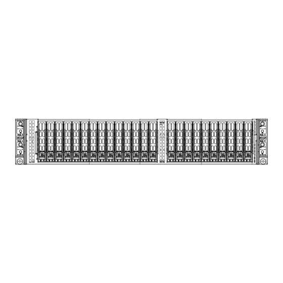
Chapter 1: Introduction Front Features The chassis front offers access to the storage drives and a control panel for each node. Hot-swap Storage Drives (24) Figure 1-2. Chassis Front View Front Chassis Features Item Feature Description Control Panels Controls a node as labeled Drive bays Six drives controlled by node A Drive bays... -
Page 12: Rear Features
SuperServer 2029BZ-HNR User's Manual Rear Features The illustration below shows the features included on the rear of the chassis. Figure 1-3. Chassis Rear View Rear Chassis Features Item Feature Description A, B, C, D Node A, B, C, D Independent computing nodes... -
Page 13: Input/Output Rear Panel
Chapter 1: Introduction Input/Output Rear Panel Each node provides the following input/output ports. Figure 1-4. I/O Panel Rear Panel I/O Ports Description No. Description VGA port Dedicated IPMI LAN USB1 (3.0) Unit Identifier Switch USB0 (3.0) Node Trays The chassis contains four separate computing node drawers, each with its own motherboard. Figure 1-5. -
Page 14: Motherboard Layout
SuperServer 2029BZ-HNR User's Manual 1.5 Motherboard Layout Below is a layout of the X11DPT-BH with jumper, connector and LED locations shown. See the table on the following page for descriptions. For detailed descriptions, pinout information and jumper settings, refer to Chapter 4. -
Page 15: Quick Reference
Chapter 1: Introduction Quick Reference Jumper Description Default Setting JBT1 Clear CMOS Open (Normal) JPME1 ME Recovery Pins 1-2 (Normal) JWD1 Watch Dog Timer Enable Pins 1-2 (Normal) JPG1 VGA Enable/Disable Pins 1-2 (Enabled) JPB1 BMC Enable Pins 1-2 (Enabled) Connector Description Battery (BT1) -
Page 16: System Block Diagram
SuperServer 2029BZ-HNR User's Manual System Block Diagram Figure 1-7. SYS-2029BZ-HNR System Block Diagram... -
Page 17: Where To Get Replacement Components
(http://www.supermicro.com/ support/rma/). Whenever possible, repack the chassis in the original Supermicro carton, using the original packaging material. If these are no longer available, be sure to pack the chassis securely, using packaging material to surround the chassis so that it does not shift within the carton and become damaged during shipping. -
Page 18: Chapter 2 Server Installation
SuperServer 2029BZ-HNR User's Manual Chapter 2 Server Installation 2.1 Overview This chapter provides advice and instructions for mounting your system in a server rack. If your system is not already fully integrated with processors, system memory etc., refer to Chapter 4 for details on installing those specific components. -
Page 19: Server Precautions
Chapter 2: Server Installation • In single rack installations, stabilizers should be attached to the rack. In multiple rack in- stallations, the racks should be coupled together. • Always make sure the rack is stable before extending a server or other component from the rack. -
Page 20: Circuit Overloading
SuperServer 2029BZ-HNR User's Manual Circuit Overloading Consideration should be given to the connection of the equipment to the power supply circuitry and the effect that any possible overloading of circuits might have on overcurrent protection and power supply wiring. Appropriate consideration of equipment nameplate ratings should be used when addressing this concern. -
Page 21: Rack Mounting Instructions
Chapter 2: Server Installation 2.3 Rack Mounting Instructions This section provides information on installing the chassis into a rack unit with the rails provided. There are a variety of rack units on the market, which may mean that the assembly procedure will differ slightly from the instructions provided. -
Page 22: Installing The Rails On A Rack
SuperServer 2029BZ-HNR User's Manual Installing the Rails on a Rack 1. Loosen the adjusting screw to allow the rear section to slide into the front section. 2. Push the small hooks on the front section of the rail into the holes on the front post of the rack and then down, until the spring-loaded pegs snap into the rack holes. -
Page 23: Chassis Installation
Chapter 2: Server Installation Chassis Installation Slide the chassis into the rack so that the bottom of the chassis slides onto the bottom lip of the rails. Figure 2-3. Sliding the Chassis into the Rack Note: Figures are for illustrative purposes only. Always install servers into racks from the bottom up. -
Page 24: Chapter 3 Maintenance And Component Installation
SuperServer 2029BZ-HNR User's Manual Chapter 3 Maintenance and Component Installation This chapter provides instructions on installing and replacing main system components. To prevent compatibility issues, only use components that match the specifications and/or part numbers given. Installation or replacement of most components require that power first be removed from the system. -
Page 25: Accessing The System
Chapter 3: Maintenance and Component Installation 3.2 Accessing the System Removing a Computing Node Drawer Node Handle Node Release Handle Figure 3-1. Removing a Node Tray Removing a Node 1. Use the operating system to power down the node. 2. Remove any cables attached to the node 3. -
Page 26: Removing The Chassis Cover
SuperServer 2029BZ-HNR User's Manual Removing the Chassis Cover You can access some chassis components, such as fans, by removing the cover. Remove two screws Figure 3-2. Removing the Chassis Cover Removing the Chassis Cover The chassis top cover can be lifted off after removing two screws. -
Page 27: Motherboard Components
Thermal grease is pre-applied on a new heatsink. No additional thermal grease is needed. • Refer to the Supermicro website for updates on processor support. • All graphics in this manual are for illustration only. Your components may look different. - Page 28 SuperServer 2029BZ-HNR User's Manual Heatsinks The 2029BZ-HNR server uses a slightly different heatsink design for each CPU. The SNK- P0067PSMB model is used for CPU2, the CPU closer to the mid-chassis fans. Figure 3-3. Heatsink SNK-P0071-VS Figure 3-4. Heatsink SNK-P0067PSMB...
-
Page 29: Overview Of The Processor Heatsink Module
Chapter 3: Maintenance and Component Installation Overview of the Processor Heatsink Module The Processor Heatsink Module (PHM) contains a heatsink, a processor carrier, and the processor. Heatsink with Thermal Grease Processor Carrier Processor Processor Heatsink Module Bottom View... -
Page 30: Creating The Processor Carrier Assembly
SuperServer 2029BZ-HNR User's Manual Creating the Processor Carrier Assembly To install a processor into the processor carrier, follow the steps below: 1. Hold the processor with the LGA lands (gold contacts) facing up. Locate the small, gold triangle in the corner of the processor and the corresponding hollowed triangle on the processor carrier. -
Page 31: Assembling The Processor Heatsink Module
Chapter 3: Maintenance and Component Installation Assembling the Processor Heatsink Module After creating the processor carrier assembly, mount it onto the heatsink to create the processor heatsink module (PHM): 1. Note the label on top of the heatsink, which marks the heatsink mounting holes as 1, 2, 3, and 4. -
Page 32: Preparing The Cpu Socket For Installation
SuperServer 2029BZ-HNR User's Manual Preparing the CPU Socket for Installation This motherboard comes with a plastic protective cover on the CPU socket. Remove it carefully to install the Processor Heatsink Module (PHM). CPU Socket with Plastic Protective Cover Remove the plastic protective cover from the CPU socket. -
Page 33: Installing The Processor Heatsink Module
Chapter 3: Maintenance and Component Installation Installing the Processor Heatsink Module After assembling the Processor Heatsink Module (PHM), install it onto the CPU socket: 1. Align hole 1 of the heatsink with the printed triangle on the CPU socket. See the left image below. -
Page 34: Memory
2666 2666 QRX4 2H-64GB 2666 2666 RDIMM 3Ds 8RX4 4H-128GB 2666 2666 LRDIMM QRx4 32 GB 64 GB 2666 2666 QRX4 2H-64GB 2666 2666 LRDIMM 8Rx4 4H-128 GB 2666 2666 Check the Supermicro website for possible updates to memory support. -
Page 35: Memory Population Guidelines
Then, if using two DIMMs per channel, install the second DIMM in the black slot. The following memory population sequence table was created based on guidelines provided by Intel to support Supermicro motherboards. The diagram is for illustrative purposes; your motherboard may look different. - Page 36 SuperServer 2029BZ-HNR User's Manual Memory Population for X11 DP Motherboard, 24 DIMM Slots When 1 CPU is used: Memory Population Sequence 1 CPU & 1 DIMM CPU1: P1-DIMMA1 1 CPU & 2 DIMMs CPU1: P1-DIMMA1/P1-DIMMD1 1 CPU & 3 DIMMs CPU1: P1-DIMMC1/P1-DIMMB1/P1-DIMMA1 1 CPU &...
- Page 37 Chapter 3: Maintenance and Component Installation Memory Population for X11 DP Motherboard, 24 DIMM Slots CPU1: P1-DIMMC1/P1-DIMMC2/P1-DIMMB1/P1-DIMMB2/P1-DIMMA1/P1-DIMMA2/ P1-DIMMD2/P1-DIMMD1/P1-DIMME2/P1-DIMME1/P1-DIMMF2/P1-DIMMF1 2 CPUs & 20 DIMMs CPU2: P2-DIMMB1/P2-DIMMB2/P2-DIMMA1/P2-DIMMA2/P2-DIMMD2/P2-DIMMD1/ P2-DIMME1/P2-DIMMF1 CPU1: P1-DIMMC1/P1-DIMMC2/P1-DIMMB1/P1-DIMMB2/P1-DIMMA1/P1-DIMMA2/ 2 CPUs & 22 DIMMs P1-DIMMD2/P1-DIMMD1/P1-DIMME2/P1-DIMME1/P1-DIMMF1 (Unbalanced: not CPU2: P2-DIMMC1/P2-DIMMC2/P2-DIMMB1/P2-DIMMB2/P2-DIMMA1/P2-DIMMA2/ recommended) P2-DIMMD2/P2-DIMMD1/P2-DIMME2/P2-DIMME1/P2-DIMMF1 CPU1: P1-DIMMC1/P1-DIMMC2/P1-DIMMB1/P1-DIMMB2/P1-DIMMA1/P1-DIMMA2/ 2 CPUs &...
-
Page 38: Installing Memory
SuperServer 2029BZ-HNR User's Manual Installing Memory ESD Precautions Electrostatic Discharge (ESD) can damage electronic com ponents including memory modules. To avoid damaging DIMM modules, it is important to handle them carefully. The following measures are generally sufficient. • Use a grounded wrist strap designed to prevent static discharge. -
Page 39: Motherboard Battery
Chapter 3: Maintenance and Component Installation Motherboard Battery The motherboard uses non-volatile memory to retain system information when system power is removed. This memory is powered by a lithium battery residing on the motherboard. Replacing the Battery Begin by removing power from the system as described in section 3.1. 1. -
Page 40: Chassis Components
The SC217 chassis supports twenty-four hot-swap 2.5" storage drives. Each node controls six NVMe drives. Note: Enterprise level NVMe drives are recommended for use in Supermicro chassis and servers. For information on recommended NVMe drives, visit the Supermicro website at https://www.supermicro.com/products/nfo/BigTwin.cfm. -
Page 41: Drive Configuration
Chapter 3: Maintenance and Component Installation Drive Configuration The SC217 chassis contains four separate computing node drawers, each with its own motherboard. Each node controls a set of six drives. If a node drawer is pulled out of the chassis, the drives associated with that node will power down. Node B controls drives Node D controls drives B1, B2, B3, B4, B5 and B6... -
Page 42: Installing Drives
SuperServer 2029BZ-HNR User's Manual Installing Drives Removing Drive Carriers from the Chassis 1. Press the release button on the drive carrier. This extends the drive carrier handle. 2. Use the handle to pull the carrier out of the chassis (Figure 3-5). - Page 43 Chapter 3: Maintenance and Component Installation Figure 3-6. Removing a Dummy Drive from the Drive Carrier Installing a Drive 1. Install a new drive into the carrier with the printed circuit board side facing down so that the mounting holes in the drive align with those in the carrier. 2.
- Page 44 SuperServer 2029BZ-HNR User's Manual Installing M.2 Solid State Drives Each node can accommodate one or two M.2 solid state drives (SSDs) using an optional carrier card (AOC-SMG3-2H8M2-B). Note: The system only supports SATA M.2 SSDs with operating temperature specification rated 70C or higher, and NVMe M.2 SSDs with operating specification rated at least 80C or higher.
- Page 45 Chapter 3: Maintenance and Component Installation 2. Insert the SSD into the socket on the expansion card. Then push it flat against the carrier card and the plastic standoff. 3. Secure the SSD by firmly inserting the standoff plug. Figure 3-10. Inserting the Standoff Plug Carrier Card Position Screws for M.2 Carrier Card Figure 3-11.
-
Page 46: Removing The M.2 Carrier Card
SuperServer 2029BZ-HNR User's Manual 6. Push the carrier card into the slot on the motherboard. With the screws provided, secure it to the side of the node chassis. 7. Replace any DIMMs that may have been removed. 8. Replace the node into the chassis, and power up the system. -
Page 47: Installing Expansion Cards
Chapter 3: Maintenance and Component Installation Installing Expansion Cards The system can accommodate two low-profile PCI-E 3.0 x16 cards per node, for a total of eight in the chassis. Installing an Expansion Card 1. Power down the node and remove it from the chassis. 2. -
Page 48: Siom Card
SuperServer 2029BZ-HNR User's Manual SIOM Card The Supermicro Input/Output module (SIOM) card provides options for network connection. It is inserted into a SIOM slot on the motherboard. This installation is usually performed by a system integrator or manufacturer. Installing the SIOM Card Before installing the motherboard into the node drawer: 1. -
Page 49: System Fans
Chapter 3: Maintenance and Component Installation System Fans Four fans provide cooling. They can be replaced without powering down the entire system. Fan speed is controlled by a system temperature setting in IPMI. If a fan fails, the remaining fans will ramp up to full speed. The system can continue to run with a failed fan. Replace any failed fan at your earliest convenience with the same type and model. - Page 50 SuperServer 2029BZ-HNR User's Manual Figure 3-16. Fans in Housing 6. Push the fan up from the bottom and out of the top of the housing. 7. Place the replacement fan into the vacant space in the housing while making sure the arrows on the top of the fan (indicating air direction) point in the same direction as the arrows on the other fans.
-
Page 51: Installing The Air Shrouds
Chapter 3: Maintenance and Component Installation Installing the Air Shrouds Air shrouds concentrate airflow to maximize fan efficiency. The system requires air shrouds for each motherboard node. Installing an Air Shroud The motherboard, any expansion cards, and all components must be installed in the node tray. Place the air shrouds as shown below. -
Page 52: Checking The Server Air Flow
SuperServer 2029BZ-HNR User's Manual Checking the Server Air Flow • Make sure there are no objects to obstruct airflow in and out of the server. • Do not operate the server without drives or drive carriers in the drive bays. -
Page 53: Power Supply
Power Supply The chassis features redundant power supplies. The power modules can be changed without powering down the system. New units can be ordered directly from Supermicro or authorized distributors. These power supplies are auto-switching capable. This feature enables them to automatically sense the input voltage and operate at a 100-120v or 180-240v. -
Page 54: Chapter 4 Motherboard Connections
SuperServer 2029BZ-HNR User's Manual Chapter 4 Motherboard Connections This section describes the connections on the motherboard and provides pinout definitions. Note that depending on how the system is configured, not all connections are required. The LEDs on the motherboard are also described here. A motherboard layout indicating component locations may be found in Chapter 1. - Page 55 A SATADOM (Device-on-Disk) is located at I-SATA6 on the motherboard. I-SATA6 is used with a Supermicro SuperDOM, which is a yellow SATADOM connector with a power pin built in, and no external power supply is needed. Supermicro SuperDOM is backward-compatible with a regular SATA HDD or SATADOM that requires an external power supply.
-
Page 56: Control Panel
SuperServer 2029BZ-HNR User's Manual Control Panel JF1 contains header pins for various control panel connections. See the figure below for the pin locations and definitions of the control panel buttons and LED indicators. All JF1 wires have been bundled into a single cable to simplify this connection. Make sure the red wire plugs into pin 1 as marked on the motherboard. - Page 57 Chapter 4: Motherboard Connections Power Fail LED The Power Fail LED connection is located on pins 5 and 6 of JF1. Power Fail LED Pin Definitions (JF1) Pin# Definition 3.3V PWR Supply Fail Overheat (OH)/Fan Fail Connect an LED cable to pins 7 and 8 of JF1 to use the Overheat/Fan Fail LED connections. The LED on pin 8 provides warnings of overheat or fan failure.
-
Page 58: Ports
SuperServer 2029BZ-HNR User's Manual Power LED The Power LED connection is located on pins 15 and 16 of JF1. Power LED Pin Definitions (JF1) Pin# Definition 3.3V Power LED NMI Button The non-maskable interrupt button header is located on pins 19 and 20 of JF1. -
Page 59: Jumpers
Chapter 4: Motherboard Connections 4.4 Jumpers Explanation of Jumpers To modify the operation of the motherboard, jumpers are used to choose between optional settings. Jumpers create shorts between two pins to change the function associated with it. Pin 1 is identified with a square solder pad on the printed circuit board. See the motherboard layout page for jumper locations. -
Page 60: Led Indicators
SuperServer 2029BZ-HNR User's Manual 4.5 LED Indicators IPMI LAN LEDs A dedicated IPMI LAN port is also included on the motherboard. The amber LED on the right of the IPMI LAN port indicates activity, while the LED on the left indicates the speed of the connection. -
Page 61: Sata Ports
Chapter 4: Motherboard Connections 4.7 SATA Ports I-SATA 3.0 and S-SATA 3.0 Ports The X11DPT-BH has eight SATA 3.0 ports (I-SATA0-5/S-SATA0-5/I-SATA6 + 1 SATA DOM). These are supported by the Intel C621 chipset. I-SATA0-5 and S-SATA0-5 are located at SXB1 and are supported by CPU1. -
Page 62: Chapter 5 Software
You must first configure RAID settings (if using RAID) before you install the Windows OS and the software drivers. To configure RAID settings, please refer to the RAID Configuration User Guides posted on our website at www.supermicro.com/support/manuals. Installing the Windows OS for a RAID System 1. -
Page 63: Driver Installation
Chapter 5: Software 5.2 Driver Installation The Supermicro FTP site contains drivers and utilities for your system at ftp://ftp.supermicro. com. Some of these must be installed, such as the chipset driver. After accessing the FTP site, go into the CDR_Images directory and locate the ISO file for your motherboard. -
Page 64: Superdoctor ® 5
5.3 SuperDoctor ® The Supermicro SuperDoctor 5 is a program that functions in a command-line or web-based interface for Windows and Linux operating systems. The program monitors such system health information as CPU temperature, system voltages, system power consumption, fan speed, and provides alerts via email or Simple Network Management Protocol (SNMP). -
Page 65: Ipmi
The X11DPT-BH supports the Intelligent Platform Management Interface (IPMI). IPMI is used to provide remote access, monitoring and management. There are several BIOS settings that are related to IPMI. For general documentation and information on IPMI, please visit our website at: http://www.supermicro.com/products/nfo/IPMI.cfm. -
Page 66: Chapter 6 Bios
SuperServer 2029BZ-HNR User's Manual Chapter 6 BIOS 6.1 Introduction This chapter describes the AMI BIOS setup utility for the X11DPT-BH and provides the instructions on navigating the setup screens. The BIOS is stored in a Flash EEPROM and can be updated. - Page 67 HH:MM:SS format. Note: The time is in the 24-hour format. For example, 5:30 P.M. appears as 17:30:00. The date's default value is 01/01/2016 after RTC reset. Supermicro X11DPT-BH (Motherboard model) BIOS Version Build Date (of the BIOS) CPLD (Complex Programmable Logic Device) Version: This item displays the CPLD version used in the system.
-
Page 68: Advanced Setup Configurations
SuperServer 2029BZ-HNR User's Manual 6.3 Advanced Setup Configurations Use the arrow keys to select the Advanced tab and press <Enter> to access the submenu items. Caution: Take caution when changing the Advanced settings. An incorrect value, a very high DRAM frequency, or an incorrect DRAM timing setting may make the system unstable. If this occurs, revert to the manufacture default settings. - Page 69 Chapter 6: BIOS Wait For "F1" If Error Use this feature to force the system to wait until the 'F1' key is pressed if an error occurs. The options are Disabled and Enabled. INT19 (Interrupt 19) Trap Response Interrupt 19 is the software interrupt that handles the boot disk function. When this item is set to Immediate, the ROM BIOS of the host adaptors will "capture"...
- Page 70 SuperServer 2029BZ-HNR User's Manual button for 4 seconds or longer. Select Instant Off to instantly power off the system as soon as the user presses the power button. The options are Instant Off and 4 Seconds Override. Throttle on Power Fail Use this feature to decrease system power by throttling CPU frequency when one power supply has failed.
- Page 71 Chapter 6: BIOS or damage the system during an attack. The default is Enable. (Refer to the Intel ® and Microsoft ® websites for more information.) Intel Virtualization Technology Select Enable to use Intel Virtualization Technology which will allow the I/O device assignments to be directly reported to the VMM (Virtual Memory Management) through the DMAR ACPI tables.
- Page 72 SuperServer 2029BZ-HNR User's Manual Advanced Power Management Configuration Power Technology This feature allows for switching between stored CPU Power Management profiles. The options are Disable, Energy Efficient and Custom. Power Performance Tuning (Available when "Power Technology" is set to Custom Select BIOS to allow the system BIOS to configure the Power-Performance Tuning Bias setting below.
- Page 73 Chapter 6: BIOS Hardware PM State Control Hardware P-States If this feature is set to Disable, hardware will choose a P-state setting for the system based on an OS request. If this feature is set to Native Mode, hardware will choose a P-state setting based on OS guidance.
- Page 74 SuperServer 2029BZ-HNR User's Manual UPI Configuration UPI General Configuration The following UPI information will display: • Number of CPU • Number of IIO • Current UPI Link Speed • Current UPI Link Frequency • UPI Global MMIO Low Base / Limit •...
- Page 75 Chapter 6: BIOS XPT Prefetch XPT Prefetch speculatively makes a copy to the memory controller of a read request being sent to the LLC. If the read request maps to the local memory address and the recent memory reads are likely to miss the LLC, a speculative read is sent to the local memory controller.
- Page 76 SuperServer 2029BZ-HNR User's Manual Data Scrambling for DDR4 Use this feature to enable or disable data scrambling for DDR4 memory. The options are Auto, Disable, and Enable. tCCD_L Relaxation If this feature is set to Enable, SPD (Serial Presence Detect) will override tCCD_L ("Col- umn to Column Delay-Long", or “Command to Command Delay-Long”...
- Page 77 Chapter 6: BIOS Mirror Mode This feature allows memory to be mirrored between two channels, providing 100% re- dundancy. The options are Disable, Mirror Mode 1LM, and Mirror Mode 2LM. UEFI ARM Mirror This options allows the system to imitate the behavior of the UEFI based Address Range Mirror with setup option.
- Page 78 SuperServer 2029BZ-HNR User's Manual Patrol Scrub Interval This feature allows you to decide how many hours the system should wait before the next complete patrol scrub is performed. Use the keyboard to enter a value from 0-24. The default setting is 24.
- Page 79 Chapter 6: BIOS PCI-E Port Max Payload Size Selecting Auto for this feature will enable the motherboard to automatically detect the maximum Transaction Layer Packet (TLP) size for the connected PCI-E device, allowing for maximum I/O efficiency. Selecting 128B or 256B will designate maximum packet size of 128 or 256.
- Page 80 SuperServer 2029BZ-HNR User's Manual PassThrough DMA Use this feature to allow devices such as network cards to access the system memory without using a processor. Select Enable to use the Non-Isoch VT_D Engine Pass Through Direct Memory Access (DMA) support. The options are Enable and Disable.
- Page 81 Chapter 6: BIOS Hot Plug Capable (Available when the device is detected by the system) Select Enable to enable hot plug support for PCIe root ports 2A~2D, which will allow the user to change the devices populated on PCI-E Slots 2A~2D without turning off the system.
- Page 82 SuperServer 2029BZ-HNR User's Manual PCIe PLL SSC Use this feature to enable PCIE PLL spread spectrum clocking (SSC). The options are Disable and Enable. Server ME (Management Engine) Configuration This feature displays the following system ME configuration settings. • Operational Firmware Version •...
- Page 83 Chapter 6: BIOS SATA Port 0 ~ Port 7 This item displays the information detected on the installed SATA drive on the particular SATA port. • Model number of drive and capacity • Software Preserve Support Port 0 ~ Port 7 Hot Plug Set this item to Enabled for hot-plugging support, which will allow the user to replace a SATA drive without shutting down the system.
- Page 84 SuperServer 2029BZ-HNR User's Manual sSATA Port 0 ~ Port 5 This item displays the information detected on the installed sSATA drive on the particular sSATA port. • Model number of drive and capacity • Software Preserve Support Port 0 ~ Port 5 Hot Plug Set this item to Enabled for hot-plugging support, which will allow the user to replace a SATA drive without shutting down the system.
- Page 85 Chapter 6: BIOS Maximum Read Request Select Auto for the system BIOS to automatically set the maximum size for a read request for a PCI-E device to enhance system performance. The options are Auto, 128 Bytes, 256 Bytes, 512 Bytes, 1024 Bytes, 2048 Bytes, and 4096 Bytes. MMCFG Base Use this item to select the low base address for PCIE adapters to increase base memory.
- Page 86 SuperServer 2029BZ-HNR User's Manual Onboard LAN1 Option ROM Use this feature to select the type of device installed in LAN Port1 used for system boot. The options are Legacy, EFI and Disabled. Onboard LAN2 Option ROM Use this feature to select the type of device installed in LAN Port2 used for system boot. The options are Legacy, EFI and Disabled.
- Page 87 Chapter 6: BIOS Ipv4 HTTP Support Use this feature to enable Ipv4 HTTP Boot Support. If this feature is disabled, it will not create the Ipv4 HTTP Boot option. The options are Disabled and Enabled. Ipv6 PXE Support Use this feature to enable Ipv6 PXE Boot Support. If this feature is disabled, it will not create the Ipv6 PXE Boot option.
- Page 88 SuperServer 2029BZ-HNR User's Manual Serial Port 2 Configuration Serial Port 2 Select Enabled to enable the onboard serial port specified by the user. The options are Enabled and Disabled. Device Settings This item displays the base I/O port address and the Interrupt Request address of a serial port specified by the user.
- Page 89 Chapter 6: BIOS Bits per second Use this feature to set the transmission speed for a serial port used in Console Redirection. Make sure that the same speed is used in the host computer and the client computer. A lower transmission speed may be required for long and busy lines.
- Page 90 SuperServer 2029BZ-HNR User's Manual Putty KeyPad This feature selects the settings for Function Keys and KeyPad used for Putty, which is a terminal emulator designed for the Windows OS. The options are VT100, LINUX, XTERMR6, SC0, ESCN, and VT400. Redirection After BIOS POST Use this feature to enable or disable legacy console redirection after BIOS POST.
- Page 91 Chapter 6: BIOS Flow Control Use this item to set the flow control for Console Redirection to prevent data loss caused by buffer overflow. Send a "Stop" signal to stop sending data when the receiving buffer is full. Send a "Start" signal to start sending data when the receiving buffer is empty. The options are None, Hardware RTS/CTS, and Software Xon/Xoff.
- Page 92 SuperServer 2029BZ-HNR User's Manual Trusted Computing (Available when a TPM device is installed and detected by the BIOS) When a TPM (Trusted-Platform Module) device is detected in your machine, the following information will be displayed. • TPM2.0 Device Found •...
- Page 93 EV DFX (Device Function On-Hide) support for the system to work properly. (EV DFX is under "IIO Configuration" in the "Chipset/North Bridge" submenu). Note 2: For more information on TPM, please refer to the TPM manual at http://www. supermicro.com/manuals/other. iSCSI Configuration ...
-
Page 94: Event Logs
SuperServer 2029BZ-HNR User's Manual 6.4 Event Logs Use this tab page to configure Event Log settings. Change SMBIOS Event Log Settings Enabling/Disabling Options SMBIOS Event Log Change this item to enable or disable all features of the SMBIOS Event Logging during system boot. - Page 95 Chapter 6: BIOS SMBIOS Event Long Standard Settings Log System Boot Event This option toggles the System Boot Event logging to enabled or disabled. The options are Disabled and Enabled. MECI The Multiple Event Count Increment (MECI) counter counts the number of occurences that a duplicate event must happen before the MECI counter is incremented.
-
Page 96: Ipmi
SuperServer 2029BZ-HNR User's Manual 6.5 IPMI Use this tab page to configure Intelligent Platform Management Interface (IPMI) settings. BMC Firmware Revision This item indicates the IPMI firmware revision used in your system. IPMI Status (Baseboard Management Controller) This item indicates the status of the IPMI firmware installed in your system. - Page 97 Chapter 6: BIOS When SEL is Full This feature allows the user to decide what the BIOS should do when the system event log is full. Select Erase Immediately to erase all events in the log when the system event log is full.
- Page 98 SuperServer 2029BZ-HNR User's Manual Configure IPV6 Support This section displays configuration features for IPV6 support. IPV6 Support Use this feature to enable IPV6 support. The options are Enabled and Disabled. Configuration Address Source This feature allows the user to select the source of the IP address for this computer. If Static is selected, you will need to know the IP address of this computer and enter it to the system manually in the field.
-
Page 99: Security
Chapter 6: BIOS 6.6 Security Use this tab page to configure Security settings. Administrator Password Use this feature to set the administrator password which is required to enter the BIOS setup utility. The length of the password should be from 3 characters to 20 characters long. Password Check Select Setup for the system to check for a password at Setup. - Page 100 SuperServer 2029BZ-HNR User's Manual Secure Boot If this item is set to Enabled, Secure Boot will be activated when a Platform Key (PK) is entered. A Platform Key is a security key used to manage the security settings of the platform firmware used in your system.
- Page 101 Chapter 6: BIOS and the key source of the Key-Exchange-Keys. The options are Save to File, Set New, Append and Erase. Authorized Signatures This feature allows the user to enter and configure a set of values to be used as Authorized Signatures for the system.
-
Page 102: Boot
SuperServer 2029BZ-HNR User's Manual 6.7 Boot Use this tab page to configure Boot Settings. Boot Mode Select Use this feature to select the type of devices that the system is going to boot from. The options are Legacy, UEFI (Unified Extensible Firmware Interface), and Dual. - Page 103 Chapter 6: BIOS When the item above -"Boot Mode Select" is set to UEFI, the following items will be display for configuration: • Boot Option #1 - Boot Option #9 Delete Boot Option Use this feature to select a boot device to delete from the boot priority list. Delete Boot Option Use this feature to remove an EFI boot option from the boot priority list.
-
Page 104: Save & Exit
SuperServer 2029BZ-HNR User's Manual 6.8 Save & Exit Use this tab page to configure Save & Exit settings. Save Options Discard Changes and Exit Select this option to quit the BIOS setup without making any permanent changes to the system configuration and reboot the computer. Select Discard Changes and Exit from the Exit menu and press <Enter>. - Page 105 Chapter 6: BIOS Discard Changes Select this option and press <Enter> to discard all the changes and return to the AMI BIOS setup utility. Default Options Restore Optimized Defaults To set this feature, select Restore Defaults from the Exit menu and press <Enter> to load manufacturer default settings which are intended for maximum system performance but not for maximum stability.
-
Page 106: Appendix A Bios Error Codes
When BIOS performs the Power On Self Test, it writes checkpoint codes to I/O port 0080h. If the computer cannot complete the boot process, a diagnostic card can be attached to the computer to read I/O port 0080h (Supermicro p/n AOC-LPC80-20). For information on AMI updates, please refer to http://www.ami.com/products/. -
Page 107: Appendix B Standardized Warning Statements For Ac Systems
Supermicro's Technical Support department for assistance. Only certified technicians should attempt to install or configure components. Read this appendix in its entirety before installing or configuring components in the Supermicro chassis. These warnings may also be found on our website at http://www.supermicro.com/about/... - Page 108 Appendix B: Standardized Warning Statements Warnung WICHTIGE SICHERHEITSHINWEISE Dieses Warnsymbol bedeutet Gefahr. Sie befinden sich in einer Situation, die zu Verletzungen führen kann. Machen Sie sich vor der Arbeit mit Geräten mit den Gefahren elektrischer Schaltungen und den üblichen Verfahren zur Vorbeugung vor Unfällen vertraut. Suchen Sie mit der am Ende jeder Warnung angegebenen Anweisungsnummer nach der jeweiligen Übersetzung in den übersetzten Sicherheitshinweisen, die zusammen mit diesem Gerät ausgeliefert wurden.
- Page 109 SuperServer 2029BZ-HNR User's Manual . ٌ ا ك ً ف حالة و ٌ يك أى تتسبب ف اصابة جسذ ة ٌ هذا الزهز ع ٌ خطز !تحذ ز قبل أى تعول عىل أي هعذات،يك عىل علن بالوخاطز ال ا ٌجوة عي الذوائز...
- Page 110 Appendix B: Standardized Warning Statements Warnung Vor dem Anschließen des Systems an die Stromquelle die Installationsanweisungen lesen. ¡Advertencia! Lea las instrucciones de instalación antes de conectar el sistema a la red de alimentación. Attention Avant de brancher le système sur la source d'alimentation, consulter les directives d'installation. .יש...
- Page 111 SuperServer 2029BZ-HNR User's Manual Warnung Dieses Produkt ist darauf angewiesen, dass im Gebäude ein Kurzschluss- bzw. Überstromschutz installiert ist. Stellen Sie sicher, dass der Nennwert der Schutzvorrichtung nicht mehr als: 250 V, 20 A beträgt. ¡Advertencia! Este equipo utiliza el sistema de protección contra cortocircuitos (o sobrecorrientes) del edificio.
- Page 112 Appendix B: Standardized Warning Statements Power Disconnection Warning Warning! The system must be disconnected from all sources of power and the power cord removed from the power supply module(s) before accessing the chassis interior to install or remove system components. 電源切断の警告...
- Page 113 SuperServer 2029BZ-HNR User's Manual يجب فصم اننظاو من جميع مصادر انطاقت وإ ز انت سهك انكهرباء من وحدة امداد انطاقت قبم انىصىل إىن امنناطق انداخهيت نههيكم نتثبيج أو إ ز انت مكىناث الجهاز 경고! 시스템에 부품들을 장착하거나 제거하기 위해서는 섀시 내부에 접근하기 전에 반드시 전원...
- Page 114 Appendix B: Standardized Warning Statements Attention Il est vivement recommandé de confier l'installation, le remplacement et la maintenance de ces équipements à des personnels qualifiés et expérimentés. !אזהרה .צוות מוסמך בלבד רשאי להתקין, להחליף את הציוד או לתת שירות עבור הציוד واملدربيه...
- Page 115 SuperServer 2029BZ-HNR User's Manual Warnung Diese Einheit ist zur Installation in Bereichen mit beschränktem Zutritt vorgesehen. Der Zutritt zu derartigen Bereichen ist nur mit einem Spezialwerkzeug, Schloss und Schlüssel oder einer sonstigen Sicherheitsvorkehrung möglich. ¡Advertencia! Esta unidad ha sido diseñada para instalación en áreas de acceso restringido. Sólo puede obtenerse acceso a una de estas áreas mediante la utilización de una herramienta especial,...
- Page 116 Appendix B: Standardized Warning Statements Battery Handling Warning! There is the danger of explosion if the battery is replaced incorrectly. Replace the battery only with the same or equivalent type recommended by the manufacturer. Dispose of used batteries according to the manufacturer's instructions 電池の取り扱い...
- Page 117 SuperServer 2029BZ-HNR User's Manual هناك خطر من انفجار يف حالة اسحبذال البطارية بطريقة غري صحيحة فعليل اسحبذال البطارية فقط بنفس النىع أو ما يعادلها مام أوصث به الرشمة املصنعة جخلص من البطاريات املسحعملة وفقا لحعليامت الرشمة الصانعة 경고! 배터리가 올바르게 교체되지 않으면 폭발의 위험이 있습니다. 기존 배터리와 동일하거나 제...
- Page 118 Appendix B: Standardized Warning Statements ¡Advertencia! Puede que esta unidad tenga más de una conexión para fuentes de alimentación. Para cortar por completo el suministro de energía, deben desconectarse todas las conexiones. Attention Cette unité peut avoir plus d'une connexion d'alimentation. Pour supprimer toute tension et tout courant électrique de l'unité, toutes les connexions d'alimentation doivent être débranchées.
- Page 119 SuperServer 2029BZ-HNR User's Manual Backplane Voltage Warning! Hazardous voltage or energy is present on the backplane when the system is operating. Use caution when servicing. バックプレーンの電圧 システムの稼働中は危険な電圧または電力が、 バックプレーン上にかかっています。 修理する際には注意く ださい。 警告 当系统正在进行时,背板上有很危险的电压或能量,进行维修时务必小心。 警告 當系統正在進行時,背板上有危險的電壓或能量,進行維修時務必小心。 Warnung Wenn das System in Betrieb ist, treten auf der Rückwandplatine gefährliche Spannungen oder Energien auf.
- Page 120 Appendix B: Standardized Warning Statements هناك خطز مه التيار الكهزبايئ أوالطاقة املىجىدة عىل اللىحة عندما يكىن النظام يعمل كه حذ ر ا عند خدمة هذا الجهاس 경고! 시스템이 동작 중일 때 후면판 (Backplane)에는 위험한 전압이나 에너지가 발생 합니다. 서비스 작업 시 주의하십시오. Waarschuwing Een gevaarlijke spanning of energie is aanwezig op de backplane wanneer het systeem in gebruik is.
- Page 121 SuperServer 2029BZ-HNR User's Manual תיאום חוקי החשמל הארצי !אזהרה .התקנת הציוד חייבת להיות תואמת לחוקי החשמל המקומיים והארציים تركيب املعدات الكهربائية يجب أن ميتثل للقىاويه املحلية والىطىية املتعلقة بالكهرباء 경고! 현 지역 및 국가의 전기 규정에 따라 장비를 설치해야 합니다.
- Page 122 Appendix B: Standardized Warning Statements Attention La mise au rebut ou le recyclage de ce produit sont généralement soumis à des lois et/ou directives de respect de l'environnement. Renseignez-vous auprès de l'organisme compétent. סילוק המוצר !אזהרה .סילוק סופי של מוצר זה חייב להיות בהתאם להנחיות וחוקי המדינה التخلص...
- Page 123 SuperServer 2029BZ-HNR User's Manual Warnung Gefährlich Bewegende Teile. Von den bewegenden Lüfterblätter fern halten. Die Lüfter drehen sich u. U. noch, wenn die Lüfterbaugruppe aus dem Chassis genommen wird. Halten Sie Finger, Schraubendreher und andere Gegenstände von den Öffnungen des Lüftergehäuses entfernt.
- Page 124 Verbindungskabeln, Stromkabeln und/oder Adapater, die Ihre örtlichen Sicherheitsstandards einhalten. Der Gebrauch von anderen Kabeln und Adapter können Fehlfunktionen oder Feuer verursachen. Die Richtlinien untersagen das Nutzen von UL oder CAS zertifizierten Kabeln (mit UL/CSA gekennzeichnet), an Geräten oder Produkten die nicht mit Supermicro gekennzeichnet sind.
- Page 125 .قيرح وأ لطع يف ببستي دق ىرخأ تالوحمو تالباك يأ مادختسا .ميلسلا سباقلاو لصوملا مجح لبق نم ةدمتعملا تالباكلا مادختسا تادعملاو ةيئابرهكلا ةزهجألل ةمالسلا نوناق رظحيUL وأCSA ( ةمالع لمحت يتلاوUL/CSA) لبق نم ةددحملاو ةينعملا تاجتنملا ريغ ىرخأ تادعم يأ عمSupermicro.
- Page 126 사항을 준수하여 제공되거나 지정된 연결 혹은 구매 케이블, 전원 케이블 및 AC 어댑터를 사용하십시오. 다른 케이블이나 어댑터를 사용하면 오작동이나 화재가 발생할 수 있습니다. 전기 용품 안전법은 UL 또는 CSA 인증 케이블 (코드에 UL / CSA가 표시된 케이블)을 Supermicro 가 지정한 제품 이외의 전기 장치에 사용하는 것을 금지합니다. Stroomkabel en AC-Adapter...
-
Page 127: Appendix C System Specifications
Appendix C: System Specifications Appendix C System Specifications Processors (per node) Dual Intel Xeon 8100/6100/5100/4100/3100 processors in a P (LGA 3647) type socket Note: Please refer to the motherboard specifications pages on our website for updates to supported processors. Chipset Intel C621 chipset BIOS AMI 32Mb SPI Flash ROM... - Page 128 SuperServer 2029BZ-HNR User's Manual Operating Environment Operating Temperature: 10º to 35º C (50º to 95º F) Non-operating Temperature: -40º to 60º C (-40º to 140º F) Operating Relative Humidity: 8% to 90% (non-condensing) Non-operating Relative Humidity: 5% to 95% (non-condensing)
-
Page 129: Appendix D Uefi Bios Recovery
Warning: Do not upgrade the BIOS unless your system has a BIOS-related issue. Flashing the wrong BIOS can cause irreparable damage to the system. In no event shall Supermicro be liable for direct, indirect, special, incidental, or consequential damages arising from a BIOS update. - Page 130 SuperServer 2029BZ-HNR User Manual The file system supported by the recovery block is FAT (including FAT12, FAT16, and FAT32) which is installed on a bootable or non-bootable USB-attached device. However, the BIOS might need several minutes to locate the SUPER.ROM file if the media size becomes too large due to the huge volumes of folders and files stored in the device.
- Page 131 Appendix D: UEFI BIOS Recovery 3. After locating the healthy BIOS binary image, the system will enter the BIOS Recovery menu as shown below. Note: At this point, you may decide if you want to start the BIOS recovery. If you decide to proceed with BIOS recovery, follow the procedures below.
- Page 132 SuperServer 2029BZ-HNR User Manual 5. After the BIOS recovery process is complete, press any key to reboot the system. 6. Using a different system, extract the BIOS package into a USB flash drive. 7. Press <Del> continuously during system boot to enter the BIOS Setup utility. From the top of the tool bar, select Boot to enter the submenu.
- Page 133 Appendix D: UEFI BIOS Recovery 8. When the UEFI Shell prompt appears, type fs# to change the device directory path. Go to the directory that contains the BIOS package you extracted earlier from Step 6. Enter flash.nsh BIOSname.### at the prompt to start the BIOS update process. Note: Do not interrupt this process until the BIOS flashing is complete.
-
Page 134: Appendix E Ipmi Crash Dump
In the event of a processor internal error (IERR) that crashes your system, you may want to provide information to support staff. You can download a crash dump of status information using IPMI. The IPMI manual is available at https://www.supermicro.com/solutions/IPMI.cfm. Check IPMI Error Log 1. - Page 135 Appendix E IPMI Crash Dump Downloading the Crash Dump File 1. In the IPMI interface, click the Miscellanous tab, then the Trouble Shooting option. 2. Click the Dump button and wait five minutes for the file to be created. (No confirm ation message will appear.) 3.
Need help?
Do you have a question about the SuperServer 2029BZ-HNR and is the answer not in the manual?
Questions and answers