Table of Contents
Advertisement
Quick Links
Advertisement
Table of Contents

Subscribe to Our Youtube Channel
Related Manuals for Supermicro 2029P-TXRT


Summary of Contents for Supermicro 2029P-TXRT
- Page 1 SuperServer ® 2029P-TXRT USER’S MANUAL Revision 1.0...
- Page 2 State of California, USA. The State of California, County of Santa Clara shall be the exclusive venue for the resolution of any such disputes. Supermicro's total liability for all claims will not exceed the price paid for the hardware product.
- Page 3 SuperServer 2029P-TXRT. Installation and maintenance should be performed by experienced technicians only. Please refer to the 2029P-TXRT server specifications page on our website for updates on supported memory, processors and operating systems (http://www.supermicro.com).
-
Page 4: Table Of Contents
Preface Contents Chapter 1 Introduction 1.1 Overview ..........................8 1.2 Unpacking the System ......................8 1.3 System Features ........................9 1.4 Server Chassis Features ....................10 Front Features ........................10 Control Panel Features ....................11 Rear Features ........................12 1.5 Motherboard Layout ......................13 Quick Reference .......................14 Quick Reference Table ......................15 Chapter 2 Server Installation 2.1 Overview ..........................18 2.2 Preparing for Setup ......................18... - Page 5 SuperServer 2029P-TXRT User's Manual Processor and Heatsink Installation ..................Memory Installation ......................Memory Support ....................... Motherboard Battery ......................3.4 Chassis Components ......................Hard Drives .......................... Hard Drive Carrier Indicators .................... DVD-ROM Drive Installation ....................System Cooling ........................Installing Fans ........................
- Page 6 Preface Chapter 4 Motherboard Connections 4.1 Power Connections ......................46 4.2 Headers and Connectors ....................47 Control Panel .........................53 NMI Button ........................54 Power Fail LED ......................55 4.3 Ports ...........................56 Rear I/O Ports ........................56 IPMI LAN Port ........................58 4.4 Jumpers ..........................59 Explanation of Jumpers ....................59 4.5 Onboard Indicators ......................61 Chapter 5 Software 5.1 OS Installation ........................63...
- Page 7 SuperServer 2029P-TXRT User's Manual Contacting Supermicro Headquarters Address: Super Micro Computer, Inc. 980 Rock Ave. San Jose, CA 95131 U.S.A. Tel: +1 (408) 503-8000 Fax: +1 (408) 503-8008 Email: marketing@supermicro.com (General Information) support@supermicro.com (Technical Support) Website: www.supermicro.com Europe Address: Super Micro Computer B.V.
-
Page 8: Overview
Chapter 1 Introduction 1.1 Overview This chapter provides a brief outline of the functions and features of the 2029P-TXRT. The 2029P-TXRT is based on the X11DPX-T motherboard and the CSE-213XAC-R1K05LP chassis. In addition to the motherboard and chassis, several important parts that are included with the system are listed below. -
Page 9: System Features
Chapter 1: Introduction 1.3 System Features The following table provides you with an overview of the main features of the 2029P-TXRT. Please refer to Appendix D for additional specifications. System Features Motherboard X11DPX-T Chassis CSE-213XAC-R1K05LP Intel® Xeon® Scalable Processors Socket Type... -
Page 10: Server Chassis Features
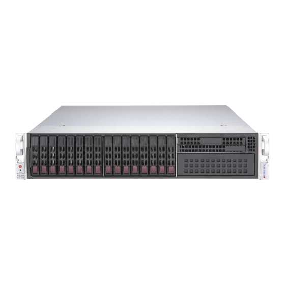
SuperServer 2029P-TXRT User's Manual 1.4 Server Chassis Features Front Features The CSE-213XAC-R1K05LP is a 2U rackmount chassis See the illustration below for the features included on the front of the chassis. Figure 1-1. Chassis Front View Front View Features Item... -
Page 11: Control Panel Features
Chapter 1: Introduction Control Panel Features The switches and LEDs located on the control panel are described below. See Chapter 4 for details on the control panel connections. Figure 1-2. Control Panel View Control Panel Features Item Feature Description The main power switch applies or removes primary power from the power Power Button supply to the server but maintains standby power. -
Page 12: Rear Features
SuperServer 2029P-TXRT User's Manual Rear Features The illustration below shows the features included on the rear of the chassis. Figure 1-3. Chassis Rear View Rear Chassis Features Item Feature Description Power Supplies Redundant 800/1000W Titanium Level power supplies I/O Ports IPMI LAN, USB, LAN, VGA (described in Chapter 4) PCI-E 3.0 Slot... -
Page 13: Motherboard Layout
Chapter 1: Introduction 1.5 Motherboard Layout Below is a layout of the X11DPX-T with jumper, connector and LED locations shown. See the table on the following page for descriptions. For detailed descriptions, pinout information and jumper settings, refer to Chapter 4. LED2 JUIDB1 COM1... -
Page 14: Quick Reference
SuperServer 2029P-TXRT User's Manual Quick Reference IPMI_LAN JUIDB1 LAN1 LED2 COM1 LEDBMC USB 0/1 LAN2 JSDCARD1 JHFI1 DESIGNED IN USA JNCSI1 FANC FAND COM2 X11DPX-T CTRL JHFI2 FAN4 REV:1.01 FAN3 JPTG1 USB 4/5 (3.0) JRK1 JIPMB1 JVRM_SEL1 JNVI2C1 CPU2 JNVI2C2... -
Page 15: Quick Reference Table
JNVI2C1 the NVMe Add-on Card on PCI-E Slot 9 (an SMCI-proprietary NVMe add-on card and cable are required; available for a Supermicro complete system only) NVMe SMBus (I C) headers used for PCI-E hot-plug SMBus clock & data connections, and for... - Page 16 SuperServer 2029P-TXRT User's Manual Connector Description JTPM1 Trusted Platform Module/Port 80 Connector JUIDB1 UID (Unit Identifier) Switch LAN1/2 LAN Ports PCI-E M.2 Connector, small form factor devices and other portable devices for High speed NVMe M.2 CONNECTOR SSDs S-SATA0/S-SATA1 SATA 3.0 Ports with Power-pin Built-in w/support of SuperDOM (Disk-On-Module)
- Page 17 Chapter 1: Introduction 16GB/s 16GB/s CPU2 Slot 9 CPU2 Slot 5 PCIE 3.0 x8 PCIE 3.0 x8 ASMedia Switch VCCP1&2 12v VR13 CPU2 Slot 10 CPU2 Slot 6 ASM1480 6+1 PHASE PCIE 3.0 x8 PCIE 3.0 x16 16GB/s 16GB/s 255W CPU2 CPU2 32GB/s...
-
Page 18: Chapter 2 Server Installation
SuperServer 2029P-TXRT User's Manual Chapter 2 Server Installation 2.1 Overview This chapter provides advice and instructions for mounting your system in a server rack. If your system is not already fully integrated with processors, system memory etc., refer to Chapter 4 for details on installing those specific components. -
Page 19: Server Precautions
Chapter 2: Server Installation • In single rack installations, stabilizers should be attached to the rack. In multiple rack in- stallations, the racks should be coupled together. • Always make sure the rack is stable before extending a server or other component from the rack. -
Page 20: Circuit Overloading
SuperServer 2029P-TXRT User's Manual Circuit Overloading Consideration should be given to the connection of the equipment to the power supply circuitry and the effect that any possible overloading of circuits might have on overcurrent protection and power supply wiring. Appropriate consideration of equipment nameplate ratings should be used when addressing this concern. -
Page 21: Installing The System Into A Rack
Chapter 2: Server Installation 2.3 Installing the System into a Rack This section provides information on installing the chassis into a rack unit with the rails provided. There are a variety of rack units on the market, which may mean that the assembly procedure will differ slightly from the instructions provided. -
Page 22: Releasing The Inner Rail
SuperServer 2029P-TXRT User's Manual Releasing the Inner Rail Each inner rail has a locking latch. This latch prevents the server from coming completely out of the rack when the chassis is pulled out for servicing. To mount the rail onto the chassis, first release the inner rail from the outer rails. -
Page 23: Installing The Inner Rails On The Chassis
Chapter 2: Server Installation Installing the Inner Rails on the Chassis Installing the Inner Rails 1. Identify the left and right inner rails. They are labeled. 2. Place the inner rail firmly against the side of the chassis, aligning the hooks on the side of the chassis with the holes in the inner rail. -
Page 24: Installing The Outer Rails Onto The Rack
SuperServer 2029P-TXRT User's Manual Installing the Outer Rails onto the Rack Installing the Outer Rails 1. Press upward on the locking tab at the rear end of the middle rail. 2. Push the middle rail back into the outer rail. -
Page 25: Sliding The Chassis Onto The Rack Rails
Chapter 2: Server Installation Sliding the Chassis onto the Rack Rails Warning: Mounting the system into the rack requires at least two people to support the chassis during installation. Please follow safety recommendations printed on the rails. Installing the Chassis into a Rack 1. -
Page 26: Chapter 3 Maintenance And Component Installation
SuperServer 2029P-TXRT User's Manual Chapter 3 Maintenance and Component Installation This chapter provides instructions on installing and replacing main system components. To prevent compatibility issues, only use components that match the specifications and/or part numbers given. Installation or replacement of most components require that power first be removed from the system. -
Page 27: Motherboard Components
Chapter 3: Maintenance and Component Installation Figure 3-1. Removing the Chassis Cover 3.3 Motherboard Components Processor and Heatsink Installation Follow the procedures in this section to install a processor (CPU) and heatsink onto the motherboard. Improper CPU installation or socket misalignment can cause serious damage to the CPU or motherboard which may require RMA repairs. -
Page 28: Assembling The Processor Package
SuperServer 2029P-TXRT User's Manual • Refer to the Supermicro website for updates on CPU support.When receiving a mother- board without a processor pre-installed, make sure that the plastic CPU socket cap is in place and none of the socket pins are bent; otherwise, contact your retailer immediately. -
Page 29: Preparing The Cpu Socket For Installation
Chapter 3: Maintenance and Component Installation Preparing the CPU Socket for Installation This motherboard comes with the CPU socket assembled in the factory. It includes a dust cover, a socket bracket, the CPU socket (Dual socket P (LGA 3647) ), and a back plate. Figure 3-3. -
Page 30: Installing The Processor Heatsink Module (Phm)
SuperServer 2029P-TXRT User's Manual Installing the Processor Heatsink Module (PHM) Note: For CPU1, install the SNK-P0068PS heatsink with the side with short fins facing the power supply modules. 1. Locate the triangle (pin 1) on the CPU socket. Also locate the pin 1 corner of the PHM that is closest to "1"... -
Page 31: Removing The Processor Heatsink Module From The Motherboard
Chapter 3: Maintenance and Component Installation Removing the Processor Heatsink Module from the Motherboard Before removing the processor heatsink module (PHM), power down as described in Section 3.1. 1. Using a T30 Torx-bit screwdriver, loosen and remove the screws on the PHM from the socket, starting with the screw marked #4, in the sequence of 4, 3, 2, 1. -
Page 32: Memory Installation
Populating these DIMM modules with a pair of memory modules of the same type and size will result in interleaved memory, which will improve memory performance. Check the Supermicro website for possible updates to memory support. DDR4 Memory Support for Two Slots per Channel... -
Page 33: Memory Population Guidelines
Then, if using two DIMMs per channel, install the second DIMM in the black slot. The following memory population sequence table was created based on guidelines provided by Intel to support Supermicro motherboards. The diagram is for illustrative purposes; your motherboard may look different. - Page 34 SuperServer 2029P-TXRT User's Manual Memory Population for X11 DP Motherboard, 16 DIMM Slots When 1 CPU is used: Memory Population Sequence 1 CPU & 1 DIMM CPU1: P1-DIMMA1 1 CPU & 2 DIMMs CPU1: P1-DIMMA1/P1-DIMMD1 1 CPU & 3 DIMMs CPU1: P1-DIMMC1/P1-DIMMB1/P1-DIMMA1 1 CPU &...
- Page 35 Chapter 3: Maintenance and Component Installation CPU2 CPU1...
-
Page 36: Dimm Installation
SuperServer 2029P-TXRT User's Manual DIMM Installation DESIGNED IN USA 1. Insert the desired number of DIMMs into X11DPX-T CTRL REV:1.01 the memory slots, starting with P1-DIMM A1. For the system to work properly, CPU2 please use memory modules of the same... -
Page 37: Motherboard Battery
The hard disk drive are sold separately. Enterprise level hard disk drives are recommended for use in Supermicro chassis and servers. For information on recommended HDDs, visit the Supermicro website at http://www.supermicro.com/products/nfo/files/storage/SAS-CompList. - Page 38 SuperServer 2029P-TXRT User's Manual Removing a Drive from a Drive Carrier Begin by removing power from the system as described in Section 3.1. 1. Unplug the power and data cables from the drive. 2. Locate the locking tab at the rear of the drive. It will be on the left side of the drive when viewed from the front of the chassis.
- Page 39 Chapter 3: Maintenance and Component Installation Dummy Drive Drive Carrier Figure 3-9. Removing a Dummy Drive from Carrier Installing a Drive into the Carrier 1. Install a new drive into the carrier with the printed circuit board side facing down so that the mounting holes in the drive align with those in the carrier.
-
Page 40: System Cooling
SuperServer 2029P-TXRT User's Manual System Cooling Four 4-cm counter-rotating fans provide the cooling for the system. Each fan unit is actually made up of two fans joined back-to-back, which rotate in opposite directions. This counter- rotating action generates exceptional airflow and is effective in dampening vibration levels. -
Page 41: Peripheral Drive Installation
The chassis includes a 5.25' bay for a variety of peripheral drive options, including a slim DVD drive or an additional hard disk drive. For a complete listing of peripheral drive options, visit the Supermicro website. Installing or Replacing a Peripheral Drive 1. -
Page 42: Installing Expansion Cards
SuperServer 2029P-TXRT User's Manual Installing Expansion Cards The 2029P-TXRT system includes eleven slots for expansion cards. The serverboard must be installed before expansion cards. Installing an Expansion Card for an LP Model Chassis 1. Power down the system and remove the cover. -
Page 43: Air Shroud
Chapter 3: Maintenance and Component Installation Air Shroud The air shroud is used to concentrate airflow to maximize fan efficiency. The air shroud does not require screws to set up. Installing the Air Shroud 1. Lay the chassis on a flat, stable surface and remove the chassis cover. 2. -
Page 44: Power Supply
SuperServer 2029P-TXRT User's Manual Power Supply The 2029P-TXRT has two 1000W redundant power supplies. They operate with a 100V to 240V input voltage. Power Supply Failure If the power supply unit fails, the system will not shut down because of a redundant power unit. - Page 45 Chapter 3: Maintenance and Component Installation Release Tab Figure 3-13. Removing/Replacing a Power Supply...
-
Page 46: Chapter 4 Motherboard Connections
SuperServer 2029P-TXRT User's Manual Chapter 4 Motherboard Connections This section describes the connections on the motherboard and provides pinout definitions. Note that depending on how the system is configured, not all connections are required. The LEDs on the motherboard are also described here. A serverboard layout indicating component locations may be found in Chapter 1. -
Page 47: Headers And Connectors
Chapter 4: Motherboard Connections Warning: To provide adequate power to your system and to avoid damaging the power sup- ply or the motherboard, be sure to connect all power connectors mentioned above to the power supply. Failure in doing so may void the manufacturer warranty on your power supply and motherboard. - Page 48 SuperServer 2029P-TXRT User's Manual S-SGPIO Header A Serial General Purpose Input/Output header (S-SGPIO) is located on the motherboard. This header is used to communicate with the enclosure management chip on the backplane. See the table below for pin definitions. SGPIO Header...
- Page 49 Chapter 4: Motherboard Connections Chassis Intrusion A Chassis Intrusion header is located at JL1 on the motherboard. Attach the appropriate cable from the chassis to the header to inform you when the chassis is opened. Chassis Intrusion Pin Definitions Pins Definition Intrusion Input Ground...
- Page 50 C621 chipset. In addition, it also has two S-SATA 3.0 ports (S-SATA0/ S-SATA1) ® that are supported by the Intel SCU. S-SATA0/1 can be used with Supermicro SuperDOMs which are yellow SATA DOM connectors with power pins built in, and do not require external power cables.
- Page 51 C2), used for PCI-E SMBus clock and data connections, provide hot-plug support via a dedicated SMBus interface. This feature is only available for a Supermicro complete system with an SMCI-proprietary NVMe add-on card and cable installed. Also, JNVI C1 and JNVI C2 are VPP headers for NVMe add-on cards.
- Page 52 (BMC) and a Network Interface Controller (NIC) for remote management. For the network sideband interface to work properly, you will need to use a NIC add-on card that supports NC-SI and also need to have a special cable. Please contact Supermicro at www.supermicro.
-
Page 53: Control Panel
Chapter 4: Motherboard Connections HFI Debug Port for Fabric CPU (JTAG_HFI1) This connector (JTAG_HFI1) is the JTAG port and provides miscellaneous signals connectivity requirements of the Fabric CPU debug port. Refer to the table below for pin definitions. HFI Debug Port for Fabric CPU Pin Definitions Pin# Definition... -
Page 54: Nmi Button
SuperServer 2029P-TXRT User's Manual NMI Button The non-maskable interrupt button header is located on pins 19 and 20 of JF1. Refer to the table below for pin definitions. NMI Button Pin Definitions (JF1) Pin# Definition Ground Power LED The Power LED connection is located on pins 15 and 16 of JF1. Refer to the table below for pin definitions. -
Page 55: Power Fail Led
Chapter 4: Motherboard Connections UID/Overheat (OH)/Fan Fail Connect an LED cable to UID/OH/Fan Fail connections on pins 7 and 8 of JF1 to provide front UID LED indication and warnings for chassis overheat/fan failure. Refer to the table below for pin definitions. UID/Overheat (OH)/Fan Fail Pin Definitions (JF1) Pin#... -
Page 56: Ports
SuperServer 2029P-TXRT User's Manual 4.3 Ports Rear I/O Ports See the figure below for the locations and descriptions of the various I/O ports on the rear of the motherboard. Figure 4-2. Rear I/O Ports Rear I/O Ports Description Description COM Port 1 USB 2.0 Port 1... - Page 57 Chapter 4: Motherboard Connections LAN Ports Two LAN ports (LAN1, LAN2) are located on the I/O back panel. These ports accept RJ45 type cables. LAN Port Pin Definition Pin# Definition Pin# Definition TX_D1+ BI_D3- TX_D1- RX_D2- RX_D2+ BI_D4+ BI_D3+ BI_D4- Universal Serial Bus (USB) Ports There are two USB 3.0 ports (USB 4/5) located on the I/O back panel.
-
Page 58: Ipmi Lan Port
SuperServer 2029P-TXRT User's Manual Unit Identifier Switch/UID LED Indicator A rear Unit Identifier (UID) switch (JUIDB1) and an rear LED Indicator (LED2) are located on the rear side of the system. The front UID LED is located on Pin 7 of the Front Control Panel (JF1). -
Page 59: Jumpers
Chapter 4: Motherboard Connections 4.4 Jumpers Explanation of Jumpers To modify the operation of the motherboard, jumpers are used to choose between optional settings. Jumpers create shorts between two pins to change the function associated with it. Pin 1 is identified with a square solder pad on the printed circuit board. See the motherboard layout page for jumper locations. - Page 60 SuperServer 2029P-TXRT User's Manual Watch Dog JWD1 controls the Watch Dog function. Watch Dog is a monitor that can reboot the system when a software application hangs. Jumping pins 1-2 will cause Watch Dog to reset the system if an application hangs. Jumping pins 2-3 will generate a non-maskable interrupt signal for the application that hangs.
-
Page 61: Onboard Indicators
Chapter 4: Motherboard Connections 4.5 Onboard Indicators LAN 1/2 LEDs Two LAN ports (LAN 1/LAN 2) are located on the I/O back panel of the motherboard. Each Ethernet LAN port has two LEDs. The green LED indicates activity, while the other Link LED may be green, amber or off to indicate the speed of the connections. - Page 62 SuperServer 2029P-TXRT User's Manual Onboard Power LED An Onboard Power LED is located at LED2 on the serverboard. When this LED is on, the system is on. Be sure to turn off the system and unplug the power cord before removing or installing components.
-
Page 63: Chapter 5 Software
You must first configure RAID settings (if using RAID) before you install the Windows OS and the software drivers. To configure RAID settings, please refer to the RAID Configuration User Guides posted on our website at www.supermicro.com/support/manuals. Installing the Windows OS for a RAID System 1. -
Page 64: Driver Installation
The Supermicro website contains drivers and utilities for your system at https://www. supermicro.com/wftp/driver. Some of these must be installed, such as the chipset driver. After accessing the website, go into the CDR_Images (in the parent directory of the above link) and locate the ISO file for your motherboard. Download this file to create a DVD of the drivers and utilities it contains. -
Page 65: Superdoctor ® 5
5.3 SuperDoctor ® The Supermicro SuperDoctor 5 is a program that functions in a command-line or web-based interface for Windows and Linux operating systems. The program monitors such system health information as CPU temperature, system voltages, system power consumption, fan speed, and provides alerts via email or Simple Network Management Protocol (SNMP). -
Page 66: Ipmi
SuperServer 2029P-TXRT User's Manual 5.4 IPMI The X11DPX-T supports the Intelligent Platform Management Interface (IPMI). IPMI is used to provide remote access, monitoring and management. There are several BIOS settings that are related to IPMI. For general documentation and information on IPMI, please visit our website at:... -
Page 67: Chapter 6 Bios
Chapter 6: BIOS Chapter 6 BIOS 6.1 Introduction This chapter describes the AMIBIOS™ Setup utility for the X11DPX-T motherboard(s). The is stored in a flash chip and can be easily upgraded using a flash program. Note: Due to periodic changes to the BIOS, some settings may have been added or deleted and might not yet be recorded in this manual. -
Page 68: Main Setup
SuperServer 2029P-TXRT User's Manual 6.2 Main Setup When you first enter the AMI BIOS setup utility, you will enter the Main setup screen. You can always return to the Main setup screen by selecting the Main tab on the top of the screen. The Main BIOS setup screen is shown below. - Page 69 Chapter 6: BIOS Memory Information Total Memory This item displays the total size of memory available in the system.
-
Page 70: Advanced Setup Configurations
SuperServer 2029P-TXRT User's Manual 6.3 Advanced Setup Configurations Use the arrow keys to select Boot Setup and press <Enter> to access the submenu items. Warning: Take caution when changing the Advanced settings. An incorrect value, a very high DRAM frequency, or an incorrect DRAM timing setting may make the system unstable. When this occurs, revert to the default to the manufacture default settings. - Page 71 Chapter 6: BIOS Wait For "F1" If Error Use this feature to force the system to wait until the 'F1' key is pressed if an error occurs. The options are Disabled and Enabled. INT19 Trap Response Interrupt 19 is the software interrupt that handles the boot disk function. When this item is set to Immediate, the ROM BIOS of the host adaptors will "capture"...
- Page 72 SuperServer 2029P-TXRT User's Manual Power Button Function This feature controls how the system shuts down when the power button is pressed. Select 4 Seconds Override for the user to power off the system after pressing and holding the power button for 4 seconds or longer. Select Instant Off to instantly power off the system as soon as the user presses the power button.
- Page 73 Chapter 6: BIOS Execute Disable Bit (Available if supported by the OS & the CPU) Select Enable to enable the Execute-Disable Bit which will allow the processor to designate areas in the system memory where an application code can execute and where it cannot, thus preventing a worm or a virus from flooding illegal codes to overwhelm the processor or damage the system during an attack.
- Page 74 SuperServer 2029P-TXRT User's Manual Extended APIC Select Enable to use the extended APIC (Advanced Programmable Interrupt Control) support to enhance power management. The options are Disable and Enable. AES-NI Select Enable to use the Intel® Advanced Encryption Standard (AES) New Instructions (NI) to ensure data security.
- Page 75 Chapter 6: BIOS change the P-State coordination type for all hardware components only. Select SW_ALL to change the P-State coordination type for all software installed in the system. Select SW_ANY to change the P-State coordination type for a particular software program specified by the user in the system.
- Page 76 SuperServer 2029P-TXRT User's Manual CPU T State Control (Available when Power Technology is set to Custom) Software Controlled T-States This feature enables the software controlled T-States support. The options are Disable and Enable Chipset Configuration Warning: Setting the wrong values in the following features may cause the system to malfunc- tion.
- Page 77 Chapter 6: BIOS IO Directory Cache (IODC) Use this feature to enable the IO Directory Cache (IODC) support. The options are Dis- able, Auto, Enable for Remote InvItoM Hybrid Push, InvItoM AllocFlow, Enable for Re- mote InvItoM Hybrid AllocNonAlloc, and Enable for Remote InvItoM and Remote WViLF. Sub NUMA Clustering (SNC) is a feature that breaks up the Last Level Cache (LLC) into clusters based on address range.
- Page 78 SuperServer 2029P-TXRT User's Manual Memory Configuration Integrated Memory Controller (iMC) Enforce POR Select Enable to enforce POR restrictions on DDR4 frequency and voltage programming. The options are POR and Disable. Memory Frequency Use this feature to set the maximum memory frequency for onboard memory modules.
- Page 79 Chapter 6: BIOS Memory Topology The item displays the information of onboard memory modules as detected by the BIOS. Memory RAS (Reliability_Availability_Serviceability) Configuration Memory RAS Configuration Setup Use this submenu to configure the following Memory RAS settings. Static Virtual Lockstep Mode Select Enable to support the static virtual lockstep mode.
- Page 80 SuperServer 2029P-TXRT User's Manual ADDDC Sparing Adaptive Double Device Data Correction (ADDDC) Sparing detects the predetermined threshold for correctable errors, copying the contents of the failing DIMM to spare memory. The failing DIMM or memory rank will then be disabled. The options are Dis- able and Enable.
- Page 81 Chapter 6: BIOS CPU1 SLOT2 PCI-E 3.0 x16 Link Speed Use this feature to select the link speed for the PCIe port. The options are Auto, Gen 1 (2.5 GT/s), Gen 2 (5 GT/s), and Gen 3 (8 GT/s). PCI-E Port Link Status PCI-E Port Link Max PCI-E Port Link Speed...
- Page 82 SuperServer 2029P-TXRT User's Manual CPU1 SLOT9 PCI-E 3.0 x16 Link Speed Use this feature to select the link speed for the PCIe port. The options are Auto, Gen 1 (2.5 GT/s), Gen 2 (5 GT/s), and Gen 3 (8 GT/s).
- Page 83 Chapter 6: BIOS PCI-E Port Link Status PCI-E Port Link Max PCI-E Port Link Speed PCI-E Port Clocking The options are Distinct and Common. If this item is set to Distinct, this component and the component at the opposite end of the Link are operating with separate refer- ence clock sources.
- Page 84 SuperServer 2029P-TXRT User's Manual CPU2 SLOT10 PCI-E 3.0 x16 Link Speed Use this feature to select the link speed for the PCIe port. The options are Auto, Gen 1 (2.5 GT/s), Gen 2 (5 GT/s), and Gen 3 (8 GT/s).
- Page 85 Chapter 6: BIOS Intel® VT for Directed I/O (VT-d) Intel VT for Directed I/O (VT-d) ® Select Enable to use Intel® Virtualization Technology support for Direct I/O VT-d support by reporting the I/O device assignments to the VMM (Virtual Machine Monitor) through the DMAR ACPI Tables.
- Page 86 SuperServer 2029P-TXRT User's Manual *If the item above "Intel® VMD for Volume Management Device" is set to Enable, the following items will be displayed: CPU1 SLOT2 PCI-E 3.0 x16 VMD (Available when the device is detected by the system) Select Enable to use the Intel® Volume Management Device Technology for this device.
- Page 87 Chapter 6: BIOS Intel® VMD for Volume Management Device on CPU2 VMD Config for PStack0 Intel® VMD for Volume Management Device Select Enable to use the Intel® Volume Management Device Technology for this stack. The options are Disable and Enable. *If the item above "Intel®...
- Page 88 SuperServer 2029P-TXRT User's Manual *If the item above "Intel® VMD for Volume Management Device" is set to Enable, the following items will be displayed: CPU2 SLOT10 PCI-E 3.0 x16 VMD (Available when the device is detected by the system) Select Enable to use the Intel® Volume Management Device Technology for this device.
- Page 89 Chapter 6: BIOS Real USB Wake Up Select Enabled to enable the wake-up function of the USB port. The options are Disabled and Enabled. Front USB Wake Up Select Enabled to enable the wake-up function of the front access USB port. The options are Disabled and Enabled.
- Page 90 SuperServer 2029P-TXRT User's Manual SATA HDD Unlock Select Enable to unlock the HDD password. The options are Disable and Enable. Aggressive Link Power Management When this item is set to Enable, the SATA AHCI controller manages the power usage of the SATA link.
- Page 91 Chapter 6: BIOS SATA RSTe Boot Info Select Enable to provide the full int13h support for SATA controller attached devices. The options are Disable and Enable. SATA RAID Option ROM/UEFI Driver Select EFI to load the EFI driver for system boot. Select Legacy to load a legacy driver for system boot.
- Page 92 SuperServer 2029P-TXRT User's Manual Aggressive Link Power Management When this item is set to Enable, the SATA AHCI controller manages the power usage of the SATA link. The controller will put the link to a low power state when the I/O is inactive for an extended period of time, and the power state will return to normal when the I/O becomes active.
- Page 93 Chapter 6: BIOS sSATA RAID Option ROM/UEFI Driver Select EFI to load the EFI driver for system boot. Select Legacy to load a legacy driver for system boot. The options are Disable, EFI, and Legacy. sSATA Port 0~ Port 1 This item displays the information detected on the installed SATA drive on the particular SATA port.
- Page 94 SuperServer 2029P-TXRT User's Manual MMIO High Granularity Size Use this item to select the high memory size according to memory-address mapping for the IO hub. The options are 1G, 4G, 16G, 64G, 256G, and 1024G. PCI PERR/SERR Support Select Enabled to activate PCI Error and System Error report handling. The options are Disabled and Enabled.
- Page 95 Chapter 6: BIOS Onboard Video Option ROM Select Legacy to boot the system using a legacy video device installed on the motherboard. The options are Disabled, Legacy, and EFI. Network Stack Configuration Network Stack Select Enabled to enable UEFI (Unified Extensible Firmware Interface) for network stack support.
- Page 96 SuperServer 2029P-TXRT User's Manual Serial Port 1 Configuration Serial Port 1 Configuration This submenu allows the user the configure settings of Serial Port 1. Serial Port 1 Select Enabled to enable the selected onboard serial port. The options are Disabled and Enabled.
- Page 97 Chapter 6: BIOS Serial Port Console Redirection COM1 Console Redirection Select Enabled to enable console redirection support for a serial port specified by the user. The options are Disabled and Enabled. *If the item above is set to Enabled, the following items will become available for user's configuration: Console Redirection Settings This feature allows the user to specify how the host computer will exchange data with the...
- Page 98 SuperServer 2029P-TXRT User's Manual Stop Bits A stop bit indicates the end of a serial data packet. Select 1 Stop Bit for standard serial data communication. Select 2 Stop Bits if slower devices are used. The options are 1 and 2.
- Page 99 Chapter 6: BIOS *If the item above is set to Enabled, the following items will become available for user's configuration: Console Redirection Settings This feature allows the user to specify how the host computer will exchange data with the client computer, which is the remote computer used by the user. SOL/COM2 Console Redirection Settings Terminal Type...
- Page 100 SuperServer 2029P-TXRT User's Manual is full. Send a "Start" signal to start sending data when the receiving buffer is empty. The options are None and Hardware RTS/CTS. VT-UTF8 Combo Key Support Select Enabled to enable VT-UTF8 Combination Key support for ANSI/VT100 terminals.
- Page 101 Chapter 6: BIOS *If the item above is set to Enabled, the following items will become available for user's configuration: Console Redirection Settings This feature allows the user to specify how the host computer will exchange data with the client computer, which is the remote computer used by the user. Out-of-Band Management Port The feature selects a serial port in a client server to be used by the Windows Emergency Management Services (EMS) to communicate with a remote host server.
- Page 102 SuperServer 2029P-TXRT User's Manual WHEA Support Select Enabled to support the Windows Hardware Error Architecture (WHEA) platform and provide a common infrastructure for the system to handle hardware errors within the Windows OS environment to reduce system crashes and to enhance system recovery and health monitoring.
- Page 103 Chapter 6: BIOS Platform Hierarchy Use this item to disable or enable platform hierarchy for platform protection. The options are Disabled and Enabled. Storage Hierarchy Use this item to disable or enable storage hierarchy for cryptographic protection. The options are Disabled and Enabled. Endorsement Hierarchy Use this item to disable or enable endorsement hierarchy for privacy control.
-
Page 104: Event Logs
SuperServer 2029P-TXRT User's Manual 6.4 Event Logs Use this feature to configure the Event Log settings. Change SMBIOS Event Log Settings Enabling/Disabling Options SMBIOS Event Log Change this item to enable or disable all features of the SMBIOS (System Management BIOS) Event Logging during system boot. - Page 105 Chapter 6: BIOS SMBIOS Event Log Standard Settings Log System Boot Event This option toggles the System Boot Event logging to enabled or disabled. The options are Enabled and Disabled. MECI The Multiple Event Count Increment (MECI) counter counts the number of occurrences that a duplicate event must happen before the MECI counter is incremented.
-
Page 106: Ipmi
SuperServer 2029P-TXRT User's Manual 6.5 IPMI Use this feature to configure Intelligent Platform Management Interface (IPMI) settings. BMC Firmware Revision This item indicates the IPMI firmware revision used in your system. IPMI STATUS (Baseboard Management Controller) This item indicates the status of the IPMI firmware installed in your system. - Page 107 Chapter 6: BIOS When SEL is Full This feature allows the user to decide what the BIOS should do when the system event log is full. Select Erase Immediately to erase all events in the log when the system event log is full.
- Page 108 SuperServer 2029P-TXRT User's Manual Station MAC Address This item displays the Station MAC address for this computer. Mac addresses are 6 two-digit hexadecimal numbers. Gateway IP Address This item displays the Gateway IP address for this computer. This should be in decimal and in dotted quad form (i.e., 172.31.0.1).
-
Page 109: Security
Chapter 6: BIOS 6.6 Security This menu allows the user to configure the following security settings for the system. Administrator Password Press Enter to set the user password which is required to enter the BIOS setup utility. The length of the password should be from 3 characters to 20 characters long. User Password Press Enter to set the user password which is required to enter the BIOS setup utility. - Page 110 SuperServer 2029P-TXRT User's Manual Secure Boot This section displays the contents of the following secure boot features: • System Mode • Secure Boot • Vendor Keys Secure Boot Use this item to enable secure boot. The options are Disabled and Enabled.
- Page 111 Chapter 6: BIOS Platform Key (PK) This feature allows the user to configure the settings of the platform keys. Set New Use this feature to load the new platform keys (PK) from the manufacturer's defaults. Key Exchange Keys (KEK) ...
-
Page 112: Boot
SuperServer 2029P-TXRT User's Manual 6.7 Boot Use this feature to configure Boot Settings: Boot mode select Use this item to select the type of device that the system is going to boot from. The options are LEGACY, UEFI, and DUAL. The default setting is DUAL. - Page 113 Chapter 6: BIOS • Legacy/UEFI/Dual Boot Order #6 • Legacy/UEFI/Dual Boot Order #7 • Legacy/UEFI/Dual Boot Order #8 • UEFI/Dual Boot Order #9 • Dual Boot Order #10 • Dual Boot Order #11 • Dual Boot Order #12 • Dual Boot Order #13 •...
- Page 114 SuperServer 2029P-TXRT User's Manual UEFI Application Boot Priorities This feature allows the user to specify which UEFI devices are boot devices. Boot Option #1 The options are UEFI: Built-in EFI Shell and Disabled. Hard Disk Drive BBS Priorities ...
-
Page 115: Save & Exit
Chapter 6: BIOS 6.8 Save & Exit Select the Save & Exit tab from the BIOS setup screen to configure the settings below. Save Options Discard Changes and Exit Select this option to quit the BIOS Setup without making any permanent changes to the system configuration, and reboot the computer. - Page 116 SuperServer 2029P-TXRT User's Manual Default Options Restore Optimized Defaults To set this feature, select Restore Optimized Defaults from the Save & Exit menu and press <Enter>. These are factory settings designed for maximum system stability, but not for maximum performance.
-
Page 117: Appendix A Bios Error Codes
Appendix A: BIOS Error Codes Appendix A BIOS Error Codes A-1 BIOS Error Beep (POST) Codes During the POST (Power-On Self-Test) routines, which are performed each time the system is powered on, errors may occur. Non-fatal errors are those which, in most cases, allow the system to continue the boot-up process. - Page 118 When BIOS performs the Power On Self Test, it writes checkpoint codes to I/O port 0080h. If the computer cannot complete the boot process, a diagnostic card can be attached to the computer to read I/O port 0080h (Supermicro p/n AOC-LPC80-20). For information on AMI updates, please refer to http://www.ami.com/products/.
-
Page 119: Appendix B Configuring Vroc Raid Settings
Then, press <Del> key continuously during system boot to enter the BIOS Setup utility. Note 1: Only use NVMe devices that have been validated by Supermicro. For the latest updates, please contact us or refer to our website at https://www.supermicro.com.tw/. - Page 120 Appendix B: Configuring VROC RAID Settings Navigate to the Advanced tab. Use the arrow keys to select Intel(R) Virtual RAID on CPU and press <Enter> to access the menu items. The following screen will appear and the All Intel VMD Controllers feature has become available.
- Page 121 SuperServer 2029P-TXRT User's Manual Use the arrow keys to select All Intel VMD Controllers and press <Enter> to access the menu items. The following screen will appear. It allows the user to create RAID volumes and configure settings of NVMe devices as detected by the system.
- Page 122 Appendix B: Configuring VROC RAID Settings B.2 Configuring RAID Settings Refer to the instructions stated in E.1 section on how to access All Intel VMD Controllers menu items. Follow the steps below to create RAID volume(s). Step 1. To create RAID volume(s), use the arrow keys to select Create RAID Volume and press <Enter>.
- Page 123 SuperServer 2029P-TXRT User's Manual Step 2. Name: This item allows the user to enter the unique name of the RAID volume. Step 3. RAID Level: This item allows the user to select the RAID level. The options are RAID0(Stripe), RAID1(Mirror), RAID5(Parity), and RAID10(RAID0+1).
- Page 124 Appendix B: Configuring VROC RAID Settings Step 4. Enable RAID spanned over VMD Controller The options are (not selected) and X (selected). Set this item to X if the RAID level you selected earlier from Step 3. will cross VMD domains. Note: For a bootable RAID volume, do not cross VMD domains.
- Page 125 SuperServer 2029P-TXRT User's Manual Step 5. Select Disks: The options are (not selected) and X (selected). Set the items one by one to X to select the desired RAID disks. Note: For RAID0/RAID1/RAID5/RAID10, the minimum number of NVMe devices re- quired is two/two/three/four respectively.
- Page 126 Appendix B: Configuring VROC RAID Settings Step 7. Capacity (MB): This item allows the user to enter the desired RAID capacity (in MB). See the right panel of the screen for the maximum volume size allowed.
- Page 127 SuperServer 2029P-TXRT User's Manual Step 8. Create Volume Use the arrow keys to select Create Volume. Press <Enter> to create a RAID level with settings shown on the screen. Refer to the following for the RAID volume(s) being created successfully.
- Page 128 Appendix B: Configuring VROC RAID Settings RAID Volumes: For detailed RAID volume information, use the arrow keys to select the desired RAID volume as shown below. RAID VOLUME INFO Press <Enter> and the following screen will appear.
- Page 129 SuperServer 2029P-TXRT User's Manual Delete On the RAID VOLUME INFO screen, use the arrow keys to select Delete and press <Enter> to delete the RAID volume you have selected earlier (see the previous page for the RAID volume selection). The following screen will appear. Options are Yes and No.
- Page 130 Appendix B: Configuring VROC RAID Settings Reset to non-RAID On the RAID VOLUME INFO screen, select the desired NVMe device from the list of RAID Member Disks. Press <Enter> and the following screen will appear. The item, Reset to non-RAID, allows the user to remove RAID data from the selected NVMe device.
- Page 131 SuperServer 2029P-TXRT User's Manual Mark as Spare Refer to the instructions stated in E.1 section on how to access All Intel VMD Controllers menu items. When the following screen appears, select the desired NVMe device from the list of Non-RAID Physical Disks.
- Page 132 Appendix B: Configuring VROC RAID Settings The item, Mark as Spare, allows the user to set the selected NVMe device as a spare disk. Use the arrow keys to select Mark as Spare and press <Enter>. The following screen will appear.
- Page 133 SuperServer 2029P-TXRT User's Manual Mark as Journal Disk Refer to the instructions stated in E.1 section on how to access All Intel VMD Controllers menu items. When the following screen appears, select the desired NVMe device from the list of Non-RAID Physical Disks.
- Page 134 Appendix B: Configuring VROC RAID Settings The item, Mark as Journal Disk, allows the user to set the selected NVMe device as a journal disk. Use the arrow keys to select Mark as Journal Disk and press <Enter>. The following screen will appear.
- Page 135 SuperServer 2029P-TXRT User's Manual B.3 Use of Journal Disk The following steps describe the use of journal disk for RAID5 volume (parity based RAID). Step 1. Refer to the instructions stated in E.1 section on how to access All Intel VMD Controllers menu items.
- Page 136 Appendix B: Configuring VROC RAID Settings RWH Policy Press <Enter> and the following screen will appear. If any device(s) from the list of Non-RAID Physical Disks has(have) been set as journal disk(s) (see pages 140 and 141), the options are Distributed PPL, Journaling Drive, and Disable. If none from the list of Non-RAID Physical Disks has been set as a journal disk (see pages 140 and 141), the options are Distributed PPL and Disable.
- Page 137 SuperServer 2029P-TXRT User's Manual Step 3. Set the item RWH Policy to Journaling Drive. Press <Enter> and the RWH JD feature will become available as shown below. RWH JD Use the arrow keys to select RWH JD. Press <Enter> and the following screen will appear.
- Page 138 Appendix B: Configuring VROC RAID Settings Step 4. Use the arrow keys and press <Enter> to select the desired journal disk from the option list of RWH JD. Step 5. For the changes to take effect, use the arrow keys to select Change RWH settings and press <Enter>.
-
Page 139: Appendix C Standardized Warning Statements For Ac Systems
Supermicro's Technical Support department for assistance. Only certified technicians should attempt to install or configure components. Read this appendix in its entirety before installing or configuring components in the Supermicro chassis. These warnings may also be found on our website at http://www.supermicro.com/about/... - Page 140 Appendix C: Standardized Warning Statements Warnung WICHTIGE SICHERHEITSHINWEISE Dieses Warnsymbol bedeutet Gefahr. Sie befinden sich in einer Situation, die zu Verletzungen führen kann. Machen Sie sich vor der Arbeit mit Geräten mit den Gefahren elektrischer Schaltungen und den üblichen Verfahren zur Vorbeugung vor Unfällen vertraut. Suchen Sie mit der am Ende jeder Warnung angegebenen Anweisungsnummer nach der jeweiligen Übersetzung in den übersetzten Sicherheitshinweisen, die zusammen mit diesem Gerät ausgeliefert wurden.
- Page 141 SuperServer 2029P-TXRT User's Manual . ٌ ا ك ً ف حالة و ٌ يك أى تتسبب ف اصابة جسذ ة ٌ هذا الزهز ع ٌ خطز !تحذ ز قبل أى تعول عىل أي هعذات،يك عىل علن بالوخاطز ال ا ٌجوة عي الذوائز...
- Page 142 Appendix C: Standardized Warning Statements Warnung Vor dem Anschließen des Systems an die Stromquelle die Installationsanweisungen lesen. ¡Advertencia! Lea las instrucciones de instalación antes de conectar el sistema a la red de alimentación. Attention Avant de brancher le système sur la source d'alimentation, consulter les directives d'installation. .יש...
- Page 143 SuperServer 2029P-TXRT User's Manual Warnung Dieses Produkt ist darauf angewiesen, dass im Gebäude ein Kurzschluss- bzw. Überstromschutz installiert ist. Stellen Sie sicher, dass der Nennwert der Schutzvorrichtung nicht mehr als: 250 V, 20 A beträgt. ¡Advertencia! Este equipo utiliza el sistema de protección contra cortocircuitos (o sobrecorrientes) del edificio.
- Page 144 Appendix C: Standardized Warning Statements Power Disconnection Warning Warning! The system must be disconnected from all sources of power and the power cord removed from the power supply module(s) before accessing the chassis interior to install or remove system components. 電源切断の警告...
- Page 145 SuperServer 2029P-TXRT User's Manual يجب فصم اننظاو من جميع مصادر انطاقت وإ ز انت سهك انكهرباء من وحدة امداد انطاقت قبم انىصىل إىن امنناطق انداخهيت نههيكم نتثبيج أو إ ز انت مكىناث الجهاز 경고! 시스템에 부품들을 장착하거나 제거하기 위해서는 섀시 내부에 접근하기 전에 반드시 전원...
- Page 146 Appendix C: Standardized Warning Statements Attention Il est vivement recommandé de confier l'installation, le remplacement et la maintenance de ces équipements à des personnels qualifiés et expérimentés. !אזהרה .צוות מוסמך בלבד רשאי להתקין, להחליף את הציוד או לתת שירות עבור הציוד واملدربيه...
- Page 147 SuperServer 2029P-TXRT User's Manual Warnung Diese Einheit ist zur Installation in Bereichen mit beschränktem Zutritt vorgesehen. Der Zutritt zu derartigen Bereichen ist nur mit einem Spezialwerkzeug, Schloss und Schlüssel oder einer sonstigen Sicherheitsvorkehrung möglich. ¡Advertencia! Esta unidad ha sido diseñada para instalación en áreas de acceso restringido. Sólo puede obtenerse acceso a una de estas áreas mediante la utilización de una herramienta especial,...
- Page 148 Appendix C: Standardized Warning Statements Battery Handling Warning! There is the danger of explosion if the battery is replaced incorrectly. Replace the battery only with the same or equivalent type recommended by the manufacturer. Dispose of used batteries according to the manufacturer's instructions 電池の取り扱い...
- Page 149 SuperServer 2029P-TXRT User's Manual هناك خطر من انفجار يف حالة اسحبذال البطارية بطريقة غري صحيحة فعليل اسحبذال البطارية فقط بنفس النىع أو ما يعادلها مام أوصث به الرشمة املصنعة جخلص من البطاريات املسحعملة وفقا لحعليامت الرشمة الصانعة 경고! 배터리가 올바르게 교체되지 않으면 폭발의 위험이 있습니다. 기존 배터리와 동일하거나 제...
- Page 150 Appendix C: Standardized Warning Statements ¡Advertencia! Puede que esta unidad tenga más de una conexión para fuentes de alimentación. Para cortar por completo el suministro de energía, deben desconectarse todas las conexiones. Attention Cette unité peut avoir plus d'une connexion d'alimentation. Pour supprimer toute tension et tout courant électrique de l'unité, toutes les connexions d'alimentation doivent être débranchées.
- Page 151 SuperServer 2029P-TXRT User's Manual Backplane Voltage Warning! Hazardous voltage or energy is present on the backplane when the system is operating. Use caution when servicing. バックプレーンの電圧 システムの稼働中は危険な電圧または電力が、 バックプレーン上にかかっています。 修理する際には注意く ださい。 警告 当系统正在进行时,背板上有很危险的电压或能量,进行维修时务必小心。 警告 當系統正在進行時,背板上有危險的電壓或能量,進行維修時務必小心。 Warnung Wenn das System in Betrieb ist, treten auf der Rückwandplatine gefährliche Spannungen oder Energien auf.
- Page 152 Appendix C: Standardized Warning Statements هناك خطز مه التيار الكهزبايئ أوالطاقة املىجىدة عىل اللىحة عندما يكىن النظام يعمل كه حذ ر ا عند خدمة هذا الجهاس 경고! 시스템이 동작 중일 때 후면판 (Backplane)에는 위험한 전압이나 에너지가 발생 합니다. 서비스 작업 시 주의하십시오. Waarschuwing Een gevaarlijke spanning of energie is aanwezig op de backplane wanneer het systeem in gebruik is.
- Page 153 SuperServer 2029P-TXRT User's Manual תיאום חוקי החשמל הארצי !אזהרה .התקנת הציוד חייבת להיות תואמת לחוקי החשמל המקומיים והארציים تركيب املعدات الكهربائية يجب أن ميتثل للقىاويه املحلية والىطىية املتعلقة بالكهرباء 경고! 현 지역 및 국가의 전기 규정에 따라 장비를 설치해야 합니다.
- Page 154 Appendix C: Standardized Warning Statements Attention La mise au rebut ou le recyclage de ce produit sont généralement soumis à des lois et/ou directives de respect de l'environnement. Renseignez-vous auprès de l'organisme compétent. סילוק המוצר !אזהרה .סילוק סופי של מוצר זה חייב להיות בהתאם להנחיות וחוקי המדינה التخلص...
- Page 155 SuperServer 2029P-TXRT User's Manual Warnung Gefährlich Bewegende Teile. Von den bewegenden Lüfterblätter fern halten. Die Lüfter drehen sich u. U. noch, wenn die Lüfterbaugruppe aus dem Chassis genommen wird. Halten Sie Finger, Schraubendreher und andere Gegenstände von den Öffnungen des Lüftergehäuses entfernt.
- Page 156 Verbindungskabeln, Stromkabeln und/oder Adapater, die Ihre örtlichen Sicherheitsstandards einhalten. Der Gebrauch von anderen Kabeln und Adapter können Fehlfunktionen oder Feuer verursachen. Die Richtlinien untersagen das Nutzen von UL oder CAS zertifizierten Kabeln (mit UL/CSA gekennzeichnet), an Geräten oder Produkten die nicht mit Supermicro gekennzeichnet sind.
- Page 157 حجم املوصل والقابس السليم. استخدام أي كابالت ومحوالت أخرى قد يتسبب يف عطل أو حريق. يحظر قانون السالمة لألجهزة الكهربائية واملعدات استخدام الكابالت املعتمدة من قبلUL أوCSA ( والتي تحمل عالمةUL/CSA) مع أي معدات أخرى غري املنتجات املعنية واملحددة من قبلSupermicro.
- Page 158 사항을 준수하여 제공되거나 지정된 연결 혹은 구매 케이블, 전원 케이블 및 AC 어댑터를 사용하십시오. 다른 케이블이나 어댑터를 사용하면 오작동이나 화재가 발생할 수 있습니다. 전기 용품 안전법은 UL 또는 CSA 인증 케이블 (코드에 UL / CSA가 표시된 케이블)을 Supermicro 가 지정한 제품 이외의 전기 장치에 사용하는 것을 금지합니다. Stroomkabel en AC-Adapter...
-
Page 159: Appendix D System Specifications
Appendix D: System Specifications Appendix D System Specifications Processors Intel® Xeon® Scalable Processors in a Dual socket P (LGA 3647) type socket Note: Please refer to the motherboard specifications pages on our website for updates to supported processors. Chipset Intel® C621 chipset BIOS AMI UEFI Memory... - Page 160 SuperServer 2029P-TXRT User's Manual Regulatory Compliance Electromagnetic Emissions: FCC Class A, EN 55032 Class A, EN 61000-3-2/3-3, CISPR 32 Class A Electromagnetic Immunity: EN 55024/CISPR 24, (EN 61000-4-2, EN 61000-4-3, EN 61000-4-4, EN 61000-4-5, EN 61000-4-6, EN 61000-4-8, EN 61000-4-11)
Need help?
Do you have a question about the 2029P-TXRT and is the answer not in the manual?
Questions and answers