Table of Contents
Advertisement
User manual
C7000 Controller for EC Tower
for ECD/U 091 (version 05), ECD/U 091, 181, 251 (versions 06, 07),
ECD/U 502 (as of version 02)
Original operating instructions
Read carefully before use!
Keep for later reference!
Version 01-2019 – 1000755 English
Free-of-charge error analysis with the MHI support app
• Available free of charge for iOS and Android
• Fault code analysis possible without Internet connection
• Regular automatic updates of fault code data
• Practical tips from S-Klima technicians
• Request callbacks from the S-Klima Service Center directly from the app
• Send photos to the S-Klima Service Center
Download
now!
Advertisement
Table of Contents

Related Manuals for Stulz S-Klima C7000


Summary of Contents for Stulz S-Klima C7000
- Page 1 User manual C7000 Controller for EC Tower for ECD/U 091 (version 05), ECD/U 091, 181, 251 (versions 06, 07), ECD/U 502 (as of version 02) Original operating instructions Read carefully before use! Keep for later reference! Version 01-2019 – 1000755 English Free-of-charge error analysis with the MHI support app •...
- Page 2 Dear Customer, Many thanks for choosing to buy a Stulz product. Stulz has been a purveyor of sophisticated technical solutions for comfort and precision climate control applications since 1947. In Germany, Stulz is the exclusive sales partner for energy-efficient comfort air-conditioning systems of Mitsubishi Heavy Industries.
-
Page 3: Table Of Contents
Contents 1. Information on this document ....................4 1.1 Scope ..............................4 1.2 Other applicable documents ......................4 2. Presentation of the control system ..................5 3. Hardware components ......................6 3.1 I/O controller (C7000 IOC) ........................6 3.1.1 PIN assignment - I/O controller ........................7 3.2 EDIO -Expansion card for digital inputs and outputs .................8 3.3 EBUS expansion board for RS485 bus ...................10 3.4 C7000 Advanced - Terminal (C7000AT) ..................11... -
Page 4: Information On This Document
1. Information on this document These operating instructions contain detailed information about operating and troubleshooting. Always keep the operating instructions at the operation site. Make sure that persons responsible for operating the product and those working on the product have fully read and understood these operating instructions. -
Page 5: Presentation Of The Control System
2. Presentation of the control system The C7000 control system offers operational reliability for A watchdog on the C7000IOC monitors the CPU function industrial applications in combination with two designs for and generates a reboot as soon as no CPU activity has the user interface. -
Page 6: Hardware Components
3. Hardware components 3.1 I/O controller (C7000 IOC) Technical data: Electrical supply: 24(+15 %) V (AC) Power consumption: 9.6 VA Fuse: 2 A inactive Operating temperature: 5 °C to 40 °C Storage temperature: -30 °C to 60 °C LEDs on the circuit board The function of the digital inputs is indicated by the green LEDs: voltage present... -
Page 7: Pin Assignment - I/O Controller
3.1.1 PIN assignment - I/O controller The assignment depends on the unit type (DX1, DX2, CW, EC tower, EC tower 2). A DX1 unit is an air conditioning unit with a refrigerant circuit; a DX2 unit is an air conditioning unit with two refrigerant circuits. A CW unit is an air conditioning unit with one or two water circuits (CW/CW2 designs). -
Page 8: Edio -Expansion Card For Digital Inputs And Outputs
3.2 EDIO -Expansion card for digital inputs and outputs 2.2 EDIO - extension board for digital in- and outputs The EDIO expansion card is only used in the following EC towers: • ECU/D 502 (size 3) as of version 02. Technical Data: Power consumption: 10,1 VA... - Page 9 Assignment - EDIO The assignment depends on the unit version (DX1, DX2, CW, EC Tower 2). Explanation see page 7. If several EDIO boards exist, the EDIO board on the lowest socket is detected as the first EDIO board and the in- and outputs are assigned correspondingly when using the "loaddefault"...
-
Page 10: Ebus Expansion Board For Rs485 Bus
3.3 EBUS expansion board for RS485 bus Circuit board design Technical data: Port 2 Power consumption: 11.3 VA Operating temperature: 5 °C to 40 °C Storage temperature: -30 °C to 60 °C Port 3 Switch for adjusting the bias and the bus termination Setting at the end of the bus for port 2: (Example) -
Page 11: C7000 Advanced - Terminal (C7000At)
None time clock Electrical supply +24 VAC * for “SDC/MIB” protocol, the Stulz bus has to be connected here. Fuse T2A Jumper X6: Pos. A: Circuit board in download mode Contrast settings for the display BA C7000 for EC Tower | EN | 01-2019 | 1000755... -
Page 12: Driver Module
3.5 Driver module The driver module has the following features: 1. A static bus termination (120 Ohm) that can be activated via a jumper. 2. A circuit to set the bias for the bus: using two jumpers, either a low bias (bus center) or a high bias (bus end) can be set. -
Page 13: C7000 Advanced User Interface
4. C7000 Advanced user interface 4.1 Operational controls <> Selector button Confirmation button Reset = Reset button Alarm Start/Stop Start/Stop button Display Audible indicator Selector button Using this button, you can select menus and change parameters. Confirmation button Using this button, you can acknowledge functions and parameters that were selected with the selector button. -
Page 14: Controller Start
If there is a WIB8000, on which time syn- > chronization is activated, located in the Stulz bus, all connected C7000ATs and C7000IOCs (via the e-bus board) apply the date and time from the WIB. This also applies to C7000ATs that are connected via an IO bus to an IOC, which in turn is connected to the WIB via an e-bus board. - Page 15 Main menu for a C7000AT If you select the C7000AT for further settings and confirm with OK, you will reach the following display with the menu branch below after enter- ing the password 0000: 1. In the BMS menu, you can adjust the global address of the C7000AT and select one of the RS232 or RS485 interfaces available on the C7000AT, as well as the protocol according to the BMS requirement.
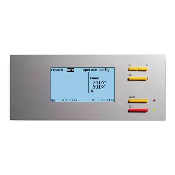
- Page 16 Main menu (for a C7000 IOC) Menu lines Alarm text Control type Temperature Main function Humidity Maintenance symbol Special software OTE Stop cause UPS operation Winter operation Stop symbol Day/night operation Unit name Alarm symbol Bus address Time Global address If you select and confirm an I/O controller, you will reach the standard window, as shown on the right.
- Page 17 Symbols for main functions If the control is in operation, the following symbols indicate the unit functions in the main menu. These symbols are not displayed in the submenus. Cooling, the cooling operating mode (DX, CW, FC, EFC, MIX) is shown on the top right. Parameter values Heating Two other displays are available instead of...
-
Page 18: Info Menus
6. Info menus 6.1. Info and Operate menus of the operation interface C7000AT Menu structure of the Info main menu The menu structure of the Info main menu is pictured in chapter “12. Menu structure of the main menu for operating the EC tower” on page 74. - Page 19 C7000 Advanced Info Values The corresponding humidity values are displayed in the same order in this window..Air/humidity 1. Value that is used for the control, can also be the zone humidity. 2. Setpoint 3. Shifted setpoint (caused by external setpoint setting or limiting control) 4.
- Page 20 Components C7000 Advanced Info If the unit is equipped with a heater, the oper- .../Heating .../Heating/Electric heater ating state of the heaters is displayed in this window. For heaters with constant control, the capacity is displayed from 0-100 %. For the warm water heater, the capacity is specified in the form of the degree of openness of the valve.
- Page 21 C7000 Advanced Info The “.../EA raw data” menu displays the .../EA raw data/A-IN .../EA raw data number of configured sensors. The “D-IN”, “D-OUT”, “A-IN”, “A-OUT” sub- menus have diagnostic purposes and display the state of each digital and analog in and outputs.
- Page 22 C7000 Advanced Info Statistics/Events All alarm signals and events (Unit on/off, watchdog (WD) restart) of one unit are displayed in this window. The signals contain the following information: Alarm text, day and time. Up to 200 signals can be stored. Statistics/Runtimes The runtimes are shown in hours.
-
Page 23: Configuration
7. Configuration First steps 1. When several units are present that are supposed to work in the bus network: Perform bus wiring and configure bus. 2. Check the equipment in the Config level. 3. Configure or deactivate additional components, e.g. air damper, water warning system or humidifiers. For the C7000AT you can do this in the Config level in the submenus of the “Components”... - Page 24 Values Air/temperature Config It is possible to have a standby unit start when an adjustable positive temperature dif- ference to the air temperature setpoint is reached. This temperature difference can be adjusted by the “Load start” parameter ➌ . The adjustment 0.0K deselects this function. ➌...
- Page 25 Values Config Air/Control type (Part 1) Here, you select the control type. The actual values display changes depending on ➊ the set control type (room/supply air). ➊ The following control types are available: - Room Room air control - Supply air Supply air control - Room, supply-air limited Room air control with supply air limit...
- Page 26 Config Values Air/Control type (Part 2) .../Temperature Room air control with supply air limit The room control with supply air limit is con- ➋ a trolled via the T/H sensor in the return air intake ➌ and via a second T/H sensor in the supply air.
- Page 27 Values Config Air/Control type (Part 3) You can set temperature limit values for the room control with supply-air limit and for the supply air control with room-air limit. Above/below the limit value, the raised/reduced temperature setpoint stays at the limit value.
- Page 28 The "OTE" parameter ➎ in the fifth line is customer specific; for normal units the setting is "STULZ". This parameter is set to “OTE” for activation of the OTE software. Via parameter ➏ in the sixth line, you can determine whether the unit may be started by a remote on/off signal.
-
Page 29: Components
7.2 Components 7.2.1 Refrigerant circuit, standard Compressor The compressor is usually installed in the air conditioning unit. However, it is also possible to actuate an external compressor. If this is the case, no installed compressor can be actuated. Set the compressor type using the following command: comp 1 type 1 (installed compressor) or: comp 1 type 2 (external compressor/ EC tower) Establishing the compressor type determines which parameters of the compressor menu are effective. - Page 30 Components/Cooling Config For ECD/U 091, 181 and 251 Select compressor 1 in the “Config/Components/Cooling” menu. This opens a new menu. For ECD/U 502 Select compressor 1 and compressor 2 in the “Config/Components/Cooling” menu. Components/Cooling Compressor In the first line, you can add a compressor to the configuration by entering a “1”. By ➎...
- Page 31 Components/Cooling Config Compressor/more/more The initialization time ➊ , which you can adjust in the first line, serves to await the initial- ization phase of the outdoor unit. The initialization time begins as soon as the controller ➊ ➋ is supplied with voltage. During the initialization time, no alarms are monitored. For the ➌...
- Page 32 PID control For the following components, a PID control can be set, consisting of a P factor, I factor and D factor: - ICC - Pump for CPP units - HGBP valve - Fan for differential temperature control - G valve - Air dampers for DFC²...
- Page 33 Instructions for adjusting a PID controller These instructions answer the following questions, using a G valve as an example. However, the measures can also be transferred to other components that are controlled by a PID controller: 1.) Why is the G valve too fast? 2.) Why is the G valve too slow? 3.) Why does the G valve oscillate? 1.) PID controller too fast ->...
-
Page 34: Air Circuit, Internal Standard Components
7.2.2 Air circuit, internal standard components Operate Components/Air Fans On the EC tower, a fan can be individually controlled. The parameters “DTC start” and “DTC range” are related to the differential temperature control. The differential temperature control is not active for the EC tower. Reduction according to temperature Enter the start temperature as a negative difference to the air temperature setpoint. - Page 35 Config Components/Air Fan/../general You add a fan to the configuration by setting the “ACTIVE” parameter to 1. You deacti- ➊ vate the fan with “0”. ➊ ➋ You define the fan type in the following lines (2 step: fan with on/off control, linear: EC ➌...
- Page 36 .../special Components/Air Fan/... (Part 2) ➊ Config ➋ ➌ ➍a Using the “START 100 %” parameter ➊ , you set a time that has to elapse before the ➍b ➎ fan control begins. This prevents an airflow alarm that could occur due to the fan rotor ➏a ➏b inertia.
- Page 37 Components/ fans (part 3) - Determining the speed Cooling priority The following decision processes are ran through by the 1 (CW) 2 (DX/EC tower) 0 (GE) controller when calculating the speed. The output speed nmax or possibly nmaxCW(DF) for dual-fluid units is chosen according to the cooling priority Are the conditions ful- Are the conditions ful- and the conditions for a fault change-over.
- Page 38 Operate Components/humidity Dehumidification The start humidity for the dehumidification is entered as a positive difference to the room ➊ humidity setpoint. ➊ ➋ To fundamentally block the dehumidifying function, the start humidity has to be set to ➌ 100 %. ➍...
-
Page 39: Air Circuit, Internal Components
7.2.3 Air circuit, internal components Operate Components/Heating Electric heater/KM heater/PWW heater Depending on the configured heating type, different parameters are decisive. ➊ The start temperature for the heater is entered as a negative difference to the room ➋ temperature setpoint. ➊... - Page 40 Config Components/heater Electric heater The PIN assignment of the electric heater is described in chapter “3.1.1 PIN assignment ➊ ➊ - I/O controller” on page 7. ➋ ➋ You add an electric heater to the configuration by setting the “ACTIVE” parameter to 1. ➌...
- Page 41 Operate Components/humidity Humidifiers Depending on the configured humidifier type, different parameters are decisive. The start humidity for the humidifier is entered as a negative difference to the room ➊ ➋ humidity setpoint. ➊ ➌ The corresponding hysteresis for the humidifier stop is only valid for humidifiers with 2 ➍...
-
Page 42: Air Circuit, External Optional Components
7.2.4 Air circuit, external optional components Operate Components/Air Air damper ➎ As long as one air damper is configured, this is opened after the control of the unit has been switched on using the start/stop button. The adjustable pre-runtime serves to open the air damper before the fan starts. This prevents the fan blowing against a closed air damper. - Page 43 Components Sensor Config You add a sensor to the configuration by setting the “ACTIVE parameter” to 1. You deactivate the sensor with “0”. ➊ ➊ ➋ You can determine the sensor type in the next line (1: current, 2: voltage). ➋...
-
Page 44: Contacts
7.2.6 Contacts Components Contacts/... Config .../ D-IN In this menu, you can assign digital inputs to external signals. Furthermore, you can determine digital inputs for the remote on/off contact ➊ , for the ➊ UPS operation ➋ and for the external cooling priority provision ➌... -
Page 45: Statistics
7.3 Statistics Config Statistics Data loggers Here, you can adjust the basic conditions for both data loggers. This includes sensor type ➊ and cycle rate (periods) ➋ , giving the intervals at which ➊ measured values of the corresponding sensor are stored. ➋... - Page 46 Config Statistics Maintenance This function supports you by monitoring the service intervals when the unit is com- missioned. ➊ If the service intervall has elapsed, the symbol appears in the main menu. ➋ You enter the service interval that you think is appropriate into the first line. It is possible ➌...
-
Page 47: Special Operating Modes
8. Special operating modes 8.1 Week program Config Values Week program The week program is based on two different temperature setpoints that you have already set in the Operate/Values/Air/Temperature menu. Setpoint 1 is represented by a “1”, setpoint 2 by a “2”. The setting is designed in a user-friendly way. -
Page 48: Zone Control
8.2 Zone control The zone concept is based on the idea of keeping a homogeneous room climate within a spatial area by spatially distributing the chilling. Setting zone num- Up to 20 zones can be defined within an I/O bus. A zone is defined if at least bers 1-20 one unit is allocated to that zone. - Page 49 Config/Zone/More/Valid alarms Alarm change-over (Z3a) So that there is a change-over when alarms occur, alarms can be defined as valid in menus Z3a, Z3b, Z3c and Z3d by adjusting the parameter to “1”. If this type of alarm (which is defined as valid) occurs, the defective unit is switched off and the standby unit with the next highest bus address is switched on.
- Page 50 Backup operation It is possible to set a backup operation using the parameter in the second line of the Z1 menu. If this parameter is set to “0”, the backup operation is deactivated. (Z1) Using this parameter you can adjust the number of defective units that leads to the backup operation being introduced.
-
Page 51: Sequencing
A special function exists for the zone control: - Sequencing. (Z1) 8.2.1 Sequencing A time-dependent unit change-over is realized using sequencing. With help from standby units, a high level of operational reliability and an even unit uti- lization is achieved. The sequencing time (parameter in the first line of menu Z1) sets the time for periodic change-overs. - Page 52 Summary of the menu items C7000 Advanced Config Zone ➊ Here you can see an overview of the adjustable parameters. Zone parameters only have ➋ to be set on one unit of the zone. Unit parameters must be set individually for each unit. ➌...
- Page 53 C7000 Advanced Config/Zone The DFC control is activated by entering a value that is different to zero for one of the ➊ two following parameters or the “Water start temperature or water hysteresis” parameter. ➋ . Air start temperature (zone parameter) ➊...
- Page 54 Config/Zone Config ➒ . Maximum fan speed (nMaxZone) (zone parameter) This value is not active for the EC tower. The set speed applies for each unit in the zone if the CW standby manager is activat- ➒ ed and if all units are running. If a unit fails, the remaining units increase their speed ➓...
-
Page 55: Manual Mode
8.3 Manual mode Components Manual mode Config When manual mode is used, the C7000 control is suspended. The manual mode menu consists of two columns of parameters which are decisive for its operation. In the first column (entitled en.), you activate manual mode for the listed component by setting the parameter to “1”. -
Page 56: Bus Communication On The Ec Tower
9. Bus communication on the EC tower 9.1 System examples with the C7000 Advanced Minimum configuration C7000 Advanced The minimum configuration consists of one unit with C7000 Advanced and I/O controller. Maximum configuration (concerning the operational possibilities and the number of units) C7000 Advanced C7000 Advanced C7000 Advanced... -
Page 57: Bus Set-Up
9.2 Bus set-up 9.2.1 General The IO bus consists of a maximum of 20 participants. On the C7000 system, only C7000 IOC or C7000AT participants can be in the IO bus. Each bus participant has its own IO bus address which must only appear once in the data bus. The IO bus addresses range from 0 to 19. -
Page 58: Manual Preparations
9.2.3 Manual preparations You need a shielded cable with lines twisted in pairs and a characteristic impedance of 120 Ω (recommendation Belden 9841), which you guide from unit to unit and connect at Dipswitch Dipswitch terminals 56-59 on each I/O controller (IOC). In the example below, the bus termination addr. -
Page 59: Bus Overview
9.2.5 Bus overview Symbol for a C7000IOC C7000AT "ME", at which this Actual temperature display appears. Operating state of the control Symbol for a C7000AT An alar m has occurred on the unit. Actual humidity Stop cause Operating state of the This unit cannot be reached. -
Page 60: Special Cases
9.2.6 Special cases Bus disconnection An important aspect concerning the IO bus display is that this can only happen from the view of the unit that you are currently on. For example, if the bus is separated between bus participants 4, 5, 6, 7, 16, 17 and bus participants 18, 19, there are two completely separate running buses. - Page 61 The bus error has an adjustable alarm time delay that waits for the bus error to be issued. This can be adjusted sep- arately for each bus participant. Address conflict The address conflict is the second error relating to the bus. An address conflict occurs when several bus participants have the same bus address.
-
Page 62: Basic Settings
10. Basic settings Unit parameter Range Value Unit name 16 characters Unit name Bus address 0 - 19 Global address 0 - 32767 Local stop 0 - 1 Monitoring stop 0 - 1 Sequencing stop 0 - 1 Terminal language 0: English 1: German Temperature unit... - Page 63 Last maintenance - Day 1 - 31 Last maintenance - Month 1 - 12 Last maintenance - Year 0 - 50 Maintenance interval 0 - 24 Maintenance alarm priority 0 - 31 Maintenance common alarm 0 - 1 UPS - D-IN input 0 - 43 UPS - Fan approved 0 - 1...
- Page 64 Week program Hour Range 0 1 2 3 4 5 6 7 8 9 10 11 12 13 14 15 16 17 18 19 20 21 22 23 Monday 0 - 2 1 1 1 1 1 1 1 1 1 1 1 1 1 1 1 1 1 1 1 1 1 1 1 1 Tuesday 0 - 2 1 1 1 1 1 1 1 1 1 1 1 1 1 1 1 1 1 1 1 1 1 1 1 1...
- Page 65 Compressor - The following table applies for ECU/D 502. Call up the “EC tower 2 basic settings” menu to adjust the EC tower configuration on the controller. EC tower 2 Range Compressor 1 Compressor 2 Start temperature 0 - 9.9 K Break 10 - 1000 s Components configured...
- Page 66 Humidifiers Range Humidifier 1 Type 1 - 2 Start, rel. humidity 0- 20 % r.h 0 % r.h Hysteresis, rel. humidity 0- 20 % r.h 5 % r.h Gradient, rel. humidity 0.5 - 20 Start, spec. humidity 0 - 20 g/kg 0 g/kg Hysteresis, spec.
- Page 67 Fans Range Fan 1 Type 1 - 2 Maximum speed 30 - 100 % 85 % CW(DF) maximum speed 30 - 100 % 85 % EFC maximum speed 30 - 100 % 85 % Offset -10 - 10 % Pre-runtime 0 - 100 s 10 s Run-on time...
- Page 68 Dehumidifier Range Dehumidifier Start 0- 100 % r.h 10 % r.h Hysteresis, relative humidity 0 - 30 % r.h 5 % r.h Start, specific humidity 0 - 30 g/kg 0 g/kg Hysteresis, specific humidity 0 - 30 g/kg 1 g/kg Dehumidification stop 0 - 10 K Dehum.
-
Page 69: Load Basic Settings For The Ec Tower
10.1 Load basic settings for the EC tower Load basic settings for EC tower of size 1 as of version 05 and size 2 as of version 06 Call up the “EC tower basic settings” menu ➊ in the Config main menu to adjust the EC tower configuration on the controller: Config >... -
Page 70: Alarm Treatment
11. Alarm treatment 11.1 Event log In the bus overview window, an alarm is indicated by a “!”. You can find out more information about this type of alarm by selecting the unit that the alarm has occurred on (in the example, unit with bus address 03) and pressing the con- firmation button. - Page 71 Operate Components Contacts/Auxiliary alarm Alarm parameters: ➍ Auxiliary alarm time delay ➍ Config You can enter the alarm text that should be displayed in the case of an alarm in the first line. ➊ ➊ You add an external alarm to the configuration by setting the “ACTIVE” parameter to 1. ➋...
-
Page 72: Alarm Texts
11.4 Alarm texts Cause Alarm text Effect LP pressure switch/LP limit LOW PRE. 1 ERROR Compressor 1 off undershot HP pressure switch/HP limit exceeded COMP 1 ERROR/HP Compressor 1 off Internal compressor circuit-breaker LP pressure switch/LP limit LOW PRE. 2 ERROR Compressor 2 off undershot HP pressure switch/HP limit exceeded... - Page 73 Alarm signals (µPC alarms) Cause Alarm text Effect RS485 bus connection faulty µPC COMM.LOSS Compressor is switched off. Sensor fracture, analog input B3 - suction gas temperature DEFECT SENSOR B3 Compressor is switched off. Sensor fracture, analog input B4 - hot-gas temperature DEFECT SENSOR B4 Compressor is switched off.
-
Page 74: Menu Structure Of The Main Menu For Operating The Ec Tower
12. Menu structure of the main menu for operating the EC tower The menu structure applies for the EC tower of size 1 as of version 05, size 2 as of version 06 and size 3 as of version 02. 12.1 Menu structure of the Info main menu No password is necessary for the info main menu. - Page 75 info statistics roomtemp. roomtemp. eventlog runtime runtime runtime options system BA C7000 for EC Tower | EN | 01-2019 | 1000755...
-
Page 76: Menu Structure Of The Operate Main Menu
12.2 Menu structure of the Operate main menu The Operate main menu, the Config main menu and the AT main menu are each protected by a password (see section “Passwords” on page 17). values temperature water humidity components operate zone Continuation Continued: next page... - Page 77 components cooling compressor compressor cooling e-heating heating e-heating humidity humidifier dehumidifc. louver sensor sensor sensor aux. ports unitalarms BA C7000 for EC Tower | EN | 01-2019 | 1000755...
-
Page 78: Menu Structure Of The Config Main Menu
12.3 Menu structure of the Config main menu The Operate main menu, the Config main menu and the AT main menu are each protected by a password (see section “Passwords” on page 17). values temperature misc. data temperature config weekprog. humidity config humidity... - Page 79 components cooling compressor compressor compressor compressor compressor cooling heating e-heating compressor e-heating humidifier humidifier humidifier dehumidific. louver Continued: Continued: See next page See next page BA C7000 for EC Tower | EN | 01-2019 | 1000755...
- Page 80 components sensor sensor sensor sensor sensor aux. ports aux. alarm unitalarms manual oper. aux. ports aux. ports value output BA C7000 for EC Tower | EN | 01-2019 | 1000755...
- Page 81 Notes BA C7000 for EC Tower | EN | 01-2019 | 1000755...
- Page 82 Notes BA C7000 for EC Tower | EN | 01-2019 | 1000755...
- Page 84 You can obtain more information from www.s-klima.de www.s-klima.de Stulz GmbH / S-Klima Division Holsteiner Chaussee 283 / 22457 Hamburg www.s-klima.de...
Need help?
Do you have a question about the S-Klima C7000 and is the answer not in the manual?
Questions and answers