
Subscribe to Our Youtube Channel
Related Manuals for Stulz E2 pluS Series


Summary of Contents for Stulz E2 pluS Series
- Page 1 pluS Series Microprocessor Controller Installation, Operation and Maintenance Manual For E pluS Controller used with CyberWall Air Handlers...
- Page 2 P L U S S E R I E S C O N T R O L L E R I N S TA L L AT I O N , O P E R AT I O N & M A I N T E N A N C E M A N UA L A B O U T S T U L Z Since it was founded in 1947, the STULZ company has evolved into one of the world’s leading system suppliers of computer room air conditioners and air handlers.
- Page 3 STULZ Air Technology Systems, Inc. This document contains confidential and proprietary information of STULZ Air Technology Systems, Inc. Distributing or photocopying this document for external distribution is in direct violation of U.S. copyright laws and is strictly prohibited without the express written consent of STULZ.
-
Page 4: Table Of Contents
DESCRIPTION ....................7 START UP ...................... 11 OPERATION ....................15 MENU SCREENS ..................18 CONTROLLER COMMUNICATION ............... 34 MAINTENANCE & REPAIRS ................. 38 PRODUCT SUPPORT ..................39 BMS POINTS LIST ..................41 05.11.23 © STULZ USA – all rights reserved... -
Page 5: General Information
STULZ E pluS Series Controllers are designed primarily to precisely operate, control and monitor STULZ CyberWall systems. Any use beyond this is deemed to be not intended. STULZ is not liable for any damage resulting from improper use. All STULZ E pluS Series Controllers are designed for indoor use. - Page 6 Equipment may contain components subject to Electrostatic Discharge (ESD). Before attempting to mount or service these electronic devices, ensure you have no charge built up by touching a ground source. When possible, use a wrist-grounding strap when working on or near electronic devices. 05.11.23 © STULZ USA – all rights reserved...
-
Page 7: Description
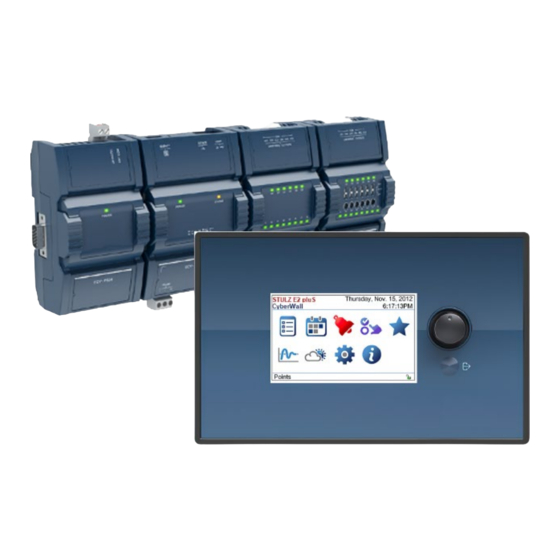
Favorites The setpoints for the system may be re-adjusted in the folder or via the BMS at any time. Favorites © STULZ USA – all rights reserved 05.11.23... - Page 8 The screens that appear on the display present data that originates from the controller. JOG DIAL EXIT BUTTON Figure 1. Graphic Terminal 05.11.23 © STULZ USA – all rights reserved...
- Page 9 Selection • Toggles the ability to acknowledge alarms. Alarms can be acknowledged in the BACnet or at the display. Icon shows locked/red if acknowledgement is not allowed, and unlocked/green if acknowledgement is allowed. © STULZ USA – all rights reserved 05.11.23...
- Page 10 UPS module in the electric box still contains stored electric power up to 32 VDC. This voltage will also be present in circuits that are electrically common to the UPS module. 05.11.23 © STULZ USA – all rights reserved...
-
Page 11: Start Up
• By editing the value. Use the Jog Dial to ‘build’ the number, one digit at a time, including decimal places, negative signs, and exponents. This is ideal to make large changes to the current value or to create values with exponents. © STULZ USA – all rights reserved 05.11.23... - Page 12 0.001, 0.01, 0.1, 1, 10, 100, or 1000. 2. Once a step value has been selected, release the Jog Dial. 3. Now rotate the Jog Dial to scroll to a value. 05.11.23 © STULZ USA – all rights reserved...
- Page 13 7. Once you have adjusted the number to the correct value (you have no more digits to create), press the Jog Dial a second time to accept the value. 8. Rotate the Jog Dial to select OK. 9. Press the Jog Dial to exit the value editing screen. © STULZ USA – all rights reserved 05.11.23...
- Page 14 LIGHT BLUE: This alarm has been configured for this point MEDIUM BLUE: This point is overridden The current context menu item selected with the Jog Dial Figure 8. Row Color Interpetation 05.11.23 © STULZ USA – all rights reserved...
-
Page 15: Operation
General The STULZ E 2 pluS Series controller is designed to control a CyberWall system in a space or process application to temperature levels defined by the user. Conditioned air is supplied to the space as needed to maintain the temperature control setpoints. - Page 16 The STULZ E 2 pluS controller's software is equipped with an operational fail safe mode. Upon a return air or supply air sensor failure, the system goes to the temperature setpoint plus a programmable temperature offset while the humidity stays at the setpoint.
- Page 17 The unit can be equipped with Dual power for the incoming power. The controller can monitor the active power to both power sources and when the power is lost to one of those sources, trigger the BMS and open the Common Alarm contact. © STULZ USA – all rights reserved 05.11.23...
-
Page 18: Menu Screens
Alarm is Configured (red background indicates point is in alarm) Value Point Name Point is overridden Point Identifier Figure 10. Typical Points Screen 05.11.23 © STULZ USA – all rights reserved... - Page 19 You can view the alarm details for the associated inputs, outputs, and values in the Points menu. Select the point that is in alarm (highlighted in red) and select Alarm details. See Interpreting Row Colors and Alarm Icons. © STULZ USA – all rights reserved 05.11.23...
- Page 20 P L U S S E R I E S C O N T R O L L E R I N S TA L L AT I O N , O P E R AT I O N & M A I N T E N A N C E M A N UA L Figure 11. Alarm Details The alarms details screen for the associated item in alarm is displayed: Figure 12. Alarm Details Screen 05.11.23 © STULZ USA – all rights reserved...
- Page 21 Alarms that were active but are currently inactive (has returned to normal) and are Inactive unacknowledged unacknowledged. The alarm list is shown below as an example of the Active acknowledged alarm type. Figure 14. Active Acknowledged Alarm List © STULZ USA – all rights reserved 05.11.23...
- Page 22 Active unacknowledged and Inactive unacknowledged alarms can be acknowledged in the Alarm Detailed Information Screen as follows. 1. Use the Jog Dial to select any item in the Alarm Detailed Information Screen and activate a list of the currently available actions. 05.11.23 © STULZ USA – all rights reserved...
- Page 23 A generic fault other than those listed above UNRELIABLE_OTHER has been detected, for example, a Digital Input is not cycling as expected, or a schedule is empty (it has not yet been configured). © STULZ USA – all rights reserved 05.11.23...
- Page 24 An overridden point can be modified or the override can be removed by selecting the point and pressing the Jog Dial to view the available actions. To select an action, see Selecting an Action. 05.11.23 © STULZ USA – all rights reserved...
- Page 25 (at priority level 8 for BACnet controllers). Auto Clears an Override value. Alarm details Shows any currently associated alarms. See Viewing Point Alarm Details (LonWorks models) on page 29 or Viewing Point Alarm Details (BACnet models) on page © STULZ USA – all rights reserved 05.11.23...
- Page 26 The following screen shows the list of grouped favorites: Figure 19. Favorites Menu Groups that have been Configured Select a favorites group from the Favorites menu to view the details: Figure 20. Selecting a Favorite 05.11.23 © STULZ USA – all rights reserved...
- Page 27 Figure 21. PID Loops Menu Use the Jog Dial to select a PID loop and view its details. The response of the PID loop is shown as a graph: Figure 22. Typical PID Configuration Screen © STULZ USA – all rights reserved 05.11.23...
- Page 28 (change to proportional, integral, derivative control or bias represented by the dashed lines) the dead band remains centered on the setpoint. Dead band Figure 23. Effect of 2°C Dead Band on PID 05.11.23 © STULZ USA – all rights reserved...
- Page 29 Thus an increase in the error will be inversely proportional to the increase in the output (the more positive the error; the more negative the output). This is used to modify the PID loop plot scale to adapt, for example, your view to the PID loop’s response Graph period time. © STULZ USA – all rights reserved 05.11.23...
- Page 30 4. Repeat these steps until the PID loop is adequately tuned. NOTE A setpoint override lasts only as long as you stay in the PID screens. Upon leaving the PID loops screens, the overridden setpoint will revert to automatic operation. 05.11.23 © STULZ USA – all rights reserved...
- Page 31 Settings Menu The settings menu allows the user to view and configure the controller’s settings such as the time, MAC address (if applicable), device ID (if applicable), etc. Figure 28. Typical Settings Menu © STULZ USA – all rights reserved 05.11.23...
- Page 32 When daylight savings time is enabled, set the time of day the daylight savings time DST stop time ends. When daylight savings time is enabled, set the amount of daylight savings time by which DST Offset the controller’s clock will be advanced. 05.11.23 © STULZ USA – all rights reserved...
- Page 33 The about menu can be customized to show the user a graphic (for example, a company logo) and textual information (for example, the integrator’s contact information). Figure 29. About Menu Example Press the Jog Dial to view the controller’s and operator interface’s firmware and bootloader versions. Figure 30. Firmware Versions © STULZ USA – all rights reserved 05.11.23...
-
Page 34: Controller Communication
1. Connect your laptop to the controller using either the PRI or SEC ethernet port on the controller. 2. Open the Windows® network connections and set the PC to a static IP address as shown below. 05.11.23 © STULZ USA – all rights reserved... - Page 35 (https:/ /192.168.1.100) to access the controller. The log in screen shown below will be loaded. Figure 33. Log In Screen 4. When prompted enter the username and password: Username: admin Password: Stulzadmin1 5. Click the “Log In” button and will be directed to the below screen. © STULZ USA – all rights reserved 05.11.23...
- Page 36 5. Optionally, export the BACnet object list from the controller by clicking on the “Export BACnet Object List” tab. A list will be exported in CSV file format that can be provided to the network integrator. 05.11.23 © STULZ USA – all rights reserved...
- Page 37 P L U S S E R I ES CO N T R O L L E R I N S TA L L AT I O N , O P E R AT I O N & M A I N T E N A N C E M A N UA L Figure 35. BACnet Settings Screen © STULZ USA – all rights reserved 05.11.23...
-
Page 38: Maintenance & Repairs
STULZ Product Support. Troubleshooting The STULZ E 2 pluS Series controller is designed for continuous and dependable operation. In the event a problem is encountered with the A/C system, the system controller may be used to diagnose the cause. -
Page 39: Product Support
Field Service STULZ recommends using the services offered by our Field Service Department to perform a Factory Start-up and assist with Commissioning activities. Factory Authorized Services help ensure your equipment is operating at its highest efficiency and provide years of trouble-free service. Contact STULZ Field Service for start-up service(s) at (888) 529-1266 or stulzfieldservice@stulz-ats.com. - Page 40 Material Authorization Number is required when returning parts. To receive credit for returned repair/replacement parts, the parts must be returned to STULZ within 30 days of the purchase date. Spare part sales over 30 days old will be considered final and the parts will remain the sole property of the ordering party.
-
Page 41: Bms Points List
Water T High Setpoint 55°F Blower BACnet Object Description Default Value Options Analog Value 19 FanSpeed_out 0.0% Analog Value 20 FanSpeedFB 0.0% Analog Value 21 Min Fan Speed 35.0% Analog Value 22 Max Fan Speed 100.0% © STULZ USA – all rights reserved 05.11.23... - Page 42 (Alarm; Normal) Binary Value 17 Low Return Temp Normal (0) (Alarm; Normal) Binary Value 18 High Return Humid Normal (0) (Alarm; Normal) Binary Value 19 Low Return Humid Normal (0) (Alarm; Normal) 05.11.23 © STULZ USA – all rights reserved...
- Page 43 Analog Value 43 days Analog Value 44 Hour hours Analog Value 45 Minute Unit: minutes Cooling Demands BACnet Object Description Default Value Options Analog Value 26 CWV1_OUT 0.0% percent Analog Value 27 CWV_2_OUT 0.0% percent © STULZ USA – all rights reserved 05.11.23...
- Page 44 LWT Offset 0°F Analog Value 40 Bottom Supply Offset 0°F PID Loop Menu BACnet Object Description Default Value Options Pid Loop 1 Supply Temp PID percent Pid Loop 2 Return Temp PID percent 05.11.23 © STULZ USA – all rights reserved...
- Page 45 BMS Keep Alive needed) Analog Value 31 BMSAliveCovDelaySP 120 s seconds Analog Value 32 BMS Keep Alive Delay 300 s seconds Binary Value 34 BV34: BMS Keep Alive Al Normal (0) (Alarm; Normal) © STULZ USA – all rights reserved 05.11.23...
- Page 46 Relative Humidity Electronic Expansion Valve STULZ STULZ Air Technology Systems, Inc. EVDVo Electronic Valve Driver Volts Entering Water Temperature Volt, Alternating Current °F Degrees Farenheit Volt, Direct Curren Free on Board Water Glycol 05.11.23 © STULZ USA – all rights reserved...
- Page 47 Mogul Lane, Mahim Paulo-SP, CEP 04708-010 Al. Jerozolimskie 162 First Quarter, Mumbai - 400 016 02 – 342 Warszawa Blenheim Rd. Epsom Surrey KT 19 9 QN www.Stulz-usa.com OZU0248A 5/11/2023 © STULZ USA – Specifications subject to change without notice.
Need help?
Do you have a question about the E2 pluS Series and is the answer not in the manual?
Questions and answers