
Related Manuals for Stulz E2 Series


Summary of Contents for Stulz E2 Series
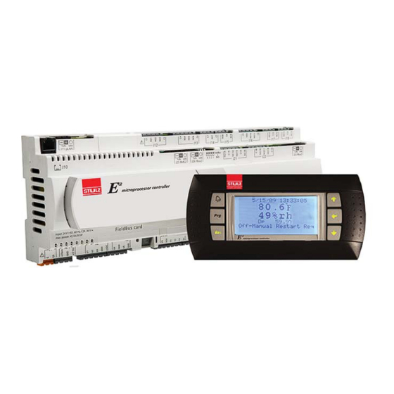
- Page 1 Series Microprocessor Controller For STULZ Perimeter Precision Air Conditioners Operation Manual...
- Page 2 STULZ Air Technology Systems, Inc. (STULZ). This document contains confi dential and proprietary information of STULZ Air Technology Systems, Inc. Distributing or photocopying this document for external distribution is in direct violation of United States copyright laws and is strictly prohibited without the express written consent of STULZ.
-
Page 3: Table Of Contents
STULZ E ERIES ONTROLLER FOR ERIMETER YSTEMS PERATION ANUAL Contents Alarms ................10 3.6.1 Summary Alarm ..............10 GENERAL INFORMATION ........1 3.6.2 Customer Alarms ............11 Forward ................1 3.6.3 Custom Alarms ..............11 Safety Summary ..............1 Operation ............12 Warnings and Cautions ..........1 General................12... - Page 4 STULZ E ERIES ONTROLLER FOR ERIMETER YSTEMS PERATION ANUAL Menu SCREENS ..........20 5.4.3 Clock Screens ..............34 Main Menu ...............20 Service Menu ..............35 Information Menu ............20 5.5.1 Cool ...................35 5.2.1 Operating Conditions ...........20 5.5.1.1 DX Cooling Screens............35 5.2.2 Shadow Unit Alarms .............21 5.5.1.2...
- Page 5 STULZ E ERIES ONTROLLER FOR ERIMETER YSTEMS PERATION ANUAL 7.1.2 Standby ................51 Figures 7.1.3 Unit Rotation ..............51 Figure 1. BMS Interface Ports ..........3 7.1.3.1 No Rotation ..............51 Figure 2. GEN1 Controller ............4 7.1.4 Out of Service ..............51 Figure 3. GEN2 Controller ............4 Setting Up a Work Group ..........52...
- Page 6 STULZ E ERIES ONTROLLER FOR ERIMETER YSTEMS PERATION ANUAL...
-
Page 7: General Information
CAUTION covered by the warranty. Prior to operating the unit, read and understand This manual is applicable to the STULZ E 2 Series Controller all instructions, recommendations and guidelines software versions for CyberAir family systems up to v3.24, contained within this manual. -
Page 8: Description
Operator interface are “Standby” are used as backup units in case of a failure of for the STULZ E 2 Series controller is provided via an attractive, either an Active or Assist unit. The role of lead controller can be door mounted user interface display panel. -
Page 9: Bms Interface
User Interface Terminals Moves the cursor into a modifi able fi eld Several user interface terminals are available with STULZ E 2 Accepts current value of a modifi able fi eld Series controllers. The A/C unit may be equipped with a large... -
Page 10: Large Bezel Terminal
STULZ E ERIES ONTROLLER FOR ERIMETER YSTEMS PERATION ANUAL 2.3.2 Large Bezel Terminal 2.4.1 GEN1 Controller Layout The GEN1 controller is shown in Figure 2. The large bezel terminal is typically mounted on the door of the A/C cabinet. It features the same backlit liquid-crystal alphanumeric display screens that the graphicterminaluses. -
Page 11: Expansion I/O Modules
STULZ E ERIES ONTROLLER FOR ERIMETER YSTEMS PERATION ANUAL The controller features called-out in Figure 3 are: 1. RJ11 telephone connector (J10) for display panel. 2. RS485 Connection for pLAN (J11). 3. Hatch for USB ports. 4. Hatch for BMS or network port. -
Page 12: Startup
STARTUP Navigating Controller Screens 3.1.1 Menu Selection The STULZ E 2 Series controller provides fi ve user selectable When the desired menu is centered in the screen with bold menus needed to view operating data and enter setpoints for capital letters and an arrow symbol pointing towards the Enter the system (see Figure 4). -
Page 13: Display Variables
STULZ E ERIES ONTROLLER FOR ERIMETER YSTEMS PERATION ANUAL 3.1.3 Display Variables Values that are already correct may simply be skipped over by using the Enter ( ) key without modifi cation of the variable. The The user interface display panel provides screens with three current value, if not changed, will be retained after pressing the (3) different forms of both the read only and the modifi... -
Page 14: Wrong Password
It is intended that access to the Factory menu screens only be the Main screen is displayed. The Main Screen is a status granted while the user is working with the guidance of STULZ screen displaying the current date, time, temperature, rela- Product Support (see Section 9.0) because incorrect settings... -
Page 15: Setpoint Adjustment
NOTE: ter Unit On appears, or after the damper enable delay Bar graph icons are used to indicate certain expires (if applicable). The STULZ logo in the display is proportionally controlled operating modes such as (CW replaced with a blower symbol and a message Unit Cooling, SCR Heat and FC Cooling). -
Page 16: Saving And Restoring Setpoint Parameters
STULZ E ERIES ONTROLLER FOR ERIMETER YSTEMS PERATION ANUAL Increase or decrease the Humidity Setpoint with the Up ( ) and Down ( ) arrow keys until the desired humidity value is shown. Press the Enter ( ) key again to accept... -
Page 17: Customer Alarms
STULZ E ERIES ONTROLLER FOR ERIMETER YSTEMS PERATION ANUAL 3.6.2 Customer Alarms A customer provided digital (on/off switching) alarm sensor may be connected to terminals provided in the electric box. This may be for any site specifi c alarm condition the user wishes to monitor that may or may not be provided in the standard A/C alarms menu;... -
Page 18: Operation
General 4.3.2 Proportional/Integral (P/I) Control The STULZ E 2 Series controller is designed to control an The controller calculates proportional control output signal(s) based on the analysis of input signals which then determines air conditioning system in a space or process application the air conditioner's required mode(s) of operation. -
Page 19: Operating Confi Gurations
STULZ E ERIES ONTROLLER FOR ERIMETER YSTEMS PERATION ANUAL Actual Temp/RH (Dewpoint) Setpoint Cool Only- No Humidifi cation Needed Psychrometric Chart Figure 5. Dewpoint Control return air temperature setpoint plus the cooling band. The On dual compressor systems, equipped with a remote... -
Page 20: Energy Savings Confi Gurations
STULZ E ERIES ONTROLLER FOR ERIMETER YSTEMS PERATION ANUAL 4.5.2.2 Alternate Water Source Cooling (AWS) The compressor(s) are turned off in stages when the control setpoint for each stage is achieved. To promote equal run An AWS system (set at the Confi guration Level) utilizes an... -
Page 21: Free Cooling (Fc)
Airfl ow/Fan Speed Control If this option is selected, an on-board steam humidifi er may be In DX based systems, the STULZ E 2 controller treats the EC turned on or off by the controller to maintain relative humidity to a control setpoint. -
Page 22: Anti-Backdraft Mode (Optional)
Downfl ow units to ensure the constant fl ow of air across the STULZ E 2 controller. See Section 5.3.4 for fan alarm messages heat load in the room. The static pressure is either directly read that may be provided. -
Page 23: Communication With The Controller
STULZ E ERIES ONTROLLER FOR ERIMETER YSTEMS PERATION ANUAL saving feature offering the ability to create up to seven operating speed algorithm based on static pressure, return temperature, or dehumidifi cation fan speed. If suction pressure rises above schedules tailored to the needs of the building. For example the high suction pressure limit, the fan speed decreases, a fi... -
Page 24: Power Transfer Performed By System Controller
4.12 Shadow Units approximately 10 seconds elapsed time which ensures the If the unit does not use an external EVD, the STULZ E 2 “switch to” power source is stable. If the compressor and fans were running at the time an automatic power transfer takes controller may be used to control up to three units as one with a place, they will restart as described in Section 3.3. - Page 25 STULZ E ERIES ONTROLLER FOR ERIMETER YSTEMS PERATION ANUAL the critical alarm is addressed. The major exceptions to this are the smoke and remote shutdown alarms which will cause all three units to shut down if they occur on any of the main or shadow units.
-
Page 26: Menu Screens
Level 3 password is needed to enter this menu. Entry to the Factory menu is intended for qualifi ed technicians working under the guidance of STULZ Product Support during start-up and commissioning of the A/C system. The password to enter this menu may be obtained by contacting Product Support. -
Page 27: Shadow Unit Alarms
STULZ E ERIES ONTROLLER FOR ERIMETER YSTEMS PERATION ANUAL 5.2.2 Shadow Unit Alarms ALARM ON UNIT Shadow unit alarm messages appear in the controller display of the main unit when an alarm occurs to a unit in the shadow group assigned to the main unit. The top... -
Page 28: Remote Sensor
STULZ E ERIES ONTROLLER FOR ERIMETER YSTEMS PERATION ANUAL 5.2.5 Remote Sensor Remote Sensor 00.0°F If the unit is equipped with an optional remote temperature and relative humidity 00%rh sensor, this screen displays temperature and relative humidity inputs as measured by the sensor. -
Page 29: Economizer Information Menu Screens
STULZ E ERIES ONTROLLER FOR ERIMETER YSTEMS PERATION ANUAL Econ Return Sensor 00.0°F 00%rh Econ Return DP 00.0°F 5.2.10 Economizer Information Menu Screens Press ( ) or ( ) Key If economizer temperature and humidity sensors are enabled, the Econ Return Air... -
Page 30: User Sensors
STULZ E ERIES ONTROLLER FOR ERIMETER YSTEMS PERATION ANUAL User Sensors 1,2 75.8 27.3 Sensor 1 Units °F 5.2.15 User Sensors Sensor 2 Units This screen appears only if the unit is confi gured with additional user specifi ed Press ( ) or ( ) Key sensors. -
Page 31: Dual Power
STULZ E ERIES ONTROLLER FOR ERIMETER YSTEMS PERATION ANUAL 5.2.21 Dual Power Dual Power A/Preferred Power If the controller is programmed to monitor dual power operation, a display screen is B/Alternate Power provided which indicates the status of the power sources. The screen message “OK”... -
Page 32: Group Information Menu Screens
STULZ E ERIES ONTROLLER FOR ERIMETER YSTEMS PERATION ANUAL Net T/H Sensors 00.0°F 00.0%rh T/H Sensor Value Local Unit 0 of 0 Lead: 1 Press ( ) or ( ) Key Network Underfl oor Static Pr 43.6 miwg All units off... -
Page 33: Modbus Fan Data
Press ( ) or ( ) Key screen is provided for each valve. 5.2.27 Software Version/Date STULZ Displays the type of A/C system the controller is confi gured for (CW, AHU, AR), the STULZ software version and its release date. E2C V: 3.24 7/22/15... -
Page 34: Alarm Log
STULZ E ERIES ONTROLLER FOR ERIMETER YSTEMS PERATION ANUAL Alarm Log “Non-Critical” and “Critical”. Any alarm may be programmed to activate the user confi gured “Custom” alarm relay contacts. MAIN MENU 5.3.2 Non-Critical Alarms Info A Non-Critical alarm will activate the alarm screen with which ALARM LOG it is associated. - Page 35 STULZ E ERIES ONTROLLER FOR ERIMETER YSTEMS PERATION ANUAL ALARM MESSAGE DESCRIPTION OF ALARM CONDITION No Airfl ow Airfl ow is inadequate for detection by the air proving switch. Filter Clogged Filter needs to be replaced. True No Flow Insuffi cient fl ow of cooling fl uid detected by fl ow switch (CW/WG units).
- Page 36 STULZ E ERIES ONTROLLER FOR ERIMETER YSTEMS PERATION ANUAL ALARM MESSAGE DESCRIPTION OF ALARM CONDITION Ebmpapst Fan#_- Communication The indicated alarm has been received from the fan. Error Ebmpapst Fan#_- Generic Error The indicated alarm has been received from the fan.
-
Page 37: Control Menu
11/04/14 Main cycle: Boot: 4.03 07/03/06 3.9 cycles/s 265ms Press ( ) Key Two Version screens are provided for information only. They show controller hardware and software details that are useful to STULZ Product Support if technical assistance is needed. -
Page 38: Setpoint Screens
STULZ E ERIES ONTROLLER FOR ERIMETER YSTEMS PERATION ANUAL 5.4.1.2 Max GPM 5.4.1 Setpoint Screens CW1 Max GPM CONTROL Max GPM: 40.0 Version Current GPM: 23.4 Del T1 Flow On: Del T1 Flow Off: Valve: 45.5% Alarm Set If the customer sensor(s) are set for Calculate GPM in The Setpoints (SET) screens below may be accessed from the Factory>Options>Enb Special Sensors, then the GPM menus... - Page 39 STULZ E ERIES ONTROLLER FOR ERIMETER YSTEMS PERATION ANUAL The High Temperature Alarm will cancel at 75 °F. Humidity Alarm High alarm Enable:Yes Conversely, the low temperature alarm will cancel when the Set Point 70.0% actual temperature rises to the Low Temperature Alarm setpoint STATUS________________ (60.0 °F) + the Offset (5.0 °F)
-
Page 40: Clock Screens
STULZ E ERIES ONTROLLER FOR ERIMETER YSTEMS PERATION ANUAL 5.4.3 Clock Screens in the cooling mode at 74.6 °F (Setpoint 72.6 °F + Offset 2 °F). Conversely, with the default cut-out offset at 0.3 °F, the cooling CONTROL mode will turn off at 72.9 °F. -
Page 41: Service Menu
The compressors rotate after each run cycle. Group Blower A Redundant Set-up screen appears next for units equipped SERVICE SERVICE with dual compressors (STULZ models VFS and CFS), if the Digital Sensors 5.5.9 -- unit is confi gured for redundant operation. BLOWER HOURS -- 5.5.6... -
Page 42: Cw Cooling Screens
STULZ E ERIES ONTROLLER FOR ERIMETER YSTEMS PERATION ANUAL 5.5.1.2 CW Cooling Screens Heat Stage 1 Cut In Offset: -2.0°F CW, AWS, FC Cut Out Offset: -0.3°F Cooling Band: 3.0°F Min deltaT1: 2.0°F STATUS--------------- Offset Multiplier CW Cut In/Out: 0.3°F Temp:73.7°F Set:72.0°F... -
Page 43: Alarms
STULZ E ERIES ONTROLLER FOR ERIMETER YSTEMS PERATION ANUAL Sensor Offsets CW Valve Dehum Valve% in dehum 100.0% Return Air Temperature Apply Offset: 0.0°F Displayed: 72.3°F Sensors Offset screen (example). The maximum position to open the CW valve, while in the NOTE dehumidifi... -
Page 44: Static Pressure Set-Up
STULZ E ERIES ONTROLLER FOR ERIMETER YSTEMS PERATION ANUAL at which the CW valve is fully open, or 100%. The max fan R e - e n t e r t h e S e r v i c e m e n u a n d s c r o l l t o t h e temperature is the offset at which the fan speed reaches the Service>Blower>Underfloor... -
Page 45: Options Menu
On/Off signal or a critical alarm. Suppress Buzzer - Allows the operator to enable or disable the alarm signal buzzer. 5.5.7.2 Unit Timers Status of fan communication with STULZ E² Unit Timers controller Startup delay: Airfl ow delay: Fan Data- Max Speed... -
Page 46: T/H Offset Scaling
STULZ E ERIES ONTROLLER FOR ERIMETER YSTEMS PERATION ANUAL operating after pushing the Enter ( ) key or after turning the valve position ever exceeds the percentage entered since the unit on with a remote on command. last fl ush cycle, the scheduled fl ush cycle will be skipped and a new interval will begin. -
Page 47: Custom Alarm Setup
STULZ E ERIES ONTROLLER FOR ERIMETER YSTEMS PERATION ANUAL 5.5.7.7 Custom Alarm Setup From the Service>Options>Custom Setup screen, press the Enter ( ) key to access Custom Setup a menu to set-up the custom alarms and sensors. Any controller alarm or signal failure Setup the alarm text, will activate the summary alarm output. - Page 48 STULZ E ERIES ONTROLLER FOR ERIMETER YSTEMS PERATION ANUAL Alarms 1 to 8 Alarms 9 to 16 Description mask Default Description mask Default Emergency shutdown Condensate pan Remote shutdown Circuit 1 low pressure Customer alarm 1 Circuit 1 high pressure Airfl...
- Page 49 STULZ E ERIES ONTROLLER FOR ERIMETER YSTEMS PERATION ANUAL Alarms 33 to 40 Alarms 41 to 48- (Sensor Failure Alarms) Description mask Default Description mask Default Loss of power Return temperature Fan alarm 4 Return humidity Damper Feedback Remote temperature...
-
Page 50: Economizer Test
STULZ E ERIES ONTROLLER FOR ERIMETER YSTEMS PERATION ANUAL for Maximum. To display the units of measure as °F instead of Alarms 65 to 72 °C in the Information menu screens, convert the minimum and maximum values (0-50 °C = 32-122 °F) and enter the values to... -
Page 51: Run Hours
STULZ E ERIES ONTROLLER FOR ERIMETER YSTEMS PERATION ANUAL 5.5.9 Run Hours SERVICE BMS Comm SERVICE GROUP Digital In Save Cfg RUN HOURS Press Enter BMS Comm Assist>Group Menu Shadow>Group Menu Press Enter Starts/Run Hours Group Confi guration Group Confi guration... -
Page 52: Factory Menu
The factory level password must be entered to gain The table that follows are some of the Factory default access to the menu. Contact STULZ Product Support for the parameters. password and for guidance when adjustments must be made at this level. -
Page 53: Economizer Operation
STULZ E ERIES ONTROLLER FOR ERIMETER YSTEMS PERATION ANUAL ECONOMIZER OPERATION The controller only provides a single output signal intended to control the outside air damper. It is up to the designer of the An economizer mode is available for applications utilizing damper system to use that signal to control a reverse-acting outdoor air-side economizing. -
Page 54: Economizer Service Menu Screens
STULZ E ERIES ONTROLLER FOR ERIMETER YSTEMS PERATION ANUAL Economizer Information Menu Screens The following display screens are available in the Information menu (Section 5.2) only if the unit is equipped for economizer o p e ra t i o n by t h e f a c t o r y. T h e s c re e n s d i s p l ay key o p e ra t i n g p a ra m et e r s fo r t h e e c o n o m i ze r m o d e . -
Page 55: Enabling Economizer Operation
STULZ E ERIES ONTROLLER FOR ERIMETER YSTEMS PERATION ANUAL Figure 11 depicts the use of the expanded dewpoint where The controller monitors the outdoor air and ceiling return air the lower dewpoint offsets of C and D have been replaced by... -
Page 56: Economizer Screen Two
CONTROLLER determined by the temperature and humidity offsets, but can It is possible for the STULZ E 2 controller to communicate in be expanded as discussed below and shown in Figure 11. multiple ways. The controller may be set up to utilize a pLAN The actual economizer values are changed on the two screens network to link with additional E²... -
Page 57: Capacity Assist
The rotation time period is typically 1 week, however it system controller display panels. may be set by the user via the Factory menu. Call STULZ Product The controller for each A/C unit in a group may be manually Support for assistance when accessing the Factory menu. -
Page 58: Setting Up A Work Group
STULZ E ERIES ONTROLLER FOR ERIMETER YSTEMS PERATION ANUAL Setting Up a Work Group A workgroup can consist of up to eight controllers (I/O boards) with pLAN addresses 1 to 8. Their corresponding display terminals will be assigned pLAN addresses from 32 down to 25. The E² controller program is defaulted with the controller address set to 1 and its terminal (display) address set to 32. -
Page 59: Assign The Terminal To The Controller
STULZ E ERIES ONTROLLER FOR ERIMETER YSTEMS PERATION ANUAL Next , press the Up ( ), Down ( ) and Enter ( ) keys simultaneously. Reconfi gure the terminal address following the steps in Section 7.2 again. This time set the terminal address to match the corresponding controller I/O board address.. If the controller is assigned address 2, then the corresponding terminal address should be set to 31 as shown in the table on the preceding page. -
Page 60: Version
STULZ E ERIES ONTROLLER FOR ERIMETER YSTEMS PERATION ANUAL The terminal for controller 1 is always addressed 32; the terminal for controller 2 is always addressed 31, and so on such that the sum of the controller address number and the terminal address number always equals 33. Therefore, when viewing controller number 1, its terminal address will be 32. - Page 61 STULZ E ERIES ONTROLLER FOR ERIMETER YSTEMS PERATION ANUAL Display Description Variables Default Unit Assign the duty of the A/C unit within the group. • Out of Service • Active The duty must be assigned for each A/C unit at its local •...
- Page 62 STULZ E ERIES ONTROLLER FOR ERIMETER YSTEMS PERATION ANUAL Display Description Variables Default Enter the delay period for capacity assist unit(s) to begin Assist Time 0 to 999 operating if it is in the capacity assist mode. Enter a temperature setpoint offset for cooling capacity Cooling Cut-In -99.9 to 99.9...
- Page 63 STULZ E ERIES ONTROLLER FOR ERIMETER YSTEMS PERATION ANUAL Service>Group>Group Averaging (Screen 6) Group Averaging Use unit sensors when Each unit in the group may be individually set to allow the lead controller in Standby or Assist to include its sensors for determining the group average value when it is for Group Averaging confi...
- Page 64 STULZ E ERIES ONTROLLER FOR ERIMETER YSTEMS PERATION ANUAL Group Alarms 17 to 24 Group Alarms 41 to 48 Description mask Default Description mask Default Fan alarm 1 DX1 discharge pressure Fan alarm 2 DX2 discharge pressure Economizer return temperature...
- Page 65 STULZ E ERIES ONTROLLER FOR ERIMETER YSTEMS PERATION ANUAL Service>Group>Group Status (Screen 8) Group Status This screen provides an overview of pLAN work group. 1 2 3 4 5 6 7 8 5 6 7 8 9 0 1 2...
-
Page 66: Group Sensor Values
STULZ E ERIES ONTROLLER FOR ERIMETER YSTEMS PERATION ANUAL 7.2.6.1 Group Sensor Values Net T/H Sensors 00.0°F This displays the current group temperature and humidity control values transmitted 00.0%rh from the Lead controller. The fi eld below displays the selected control T/H sensor T/H Sensor Value Local arrangement (lead, avg, min, max, local) depending upon how the group is set-up. -
Page 67: Bms Communication
A communication port on the expansion card (see Section 2.2.6) See the Addendum to the E2 Series Controller Manual For allows the controller to be fi eld connected to a central Building CyberAiR (CFS) Systems, OCS0108 for the E²... -
Page 68: Maintenance And Repairs
Under normal operating conditions and with the proper Troubleshooting preventive maintenance, the unit should provide excellent The STULZ E 2 Series controller is designed for continuous service for many years. If necessary, the unit may be returned to the manufacturer for major overhaul and refurbishment. All and dependable operation. -
Page 69: Control I/O Module Signal Led's
Control I/O Module Signal LED's The GEN1 STULZ E 2 controller includes 3 signal LED's (red, yellow and green) that provide information on the operation of the control module and status of the connection to the pLAN. These signal LED's are positioned adjacent to the yellow, "Power On" LED (see Figure 2). -
Page 70: Product Support
The customer is responsible for the shipping cost incurred validated by STULZ Product Support. for returning the defective part(s) back to STULZ. Return of The STULZ Product Support coordinates all Factory defective part(s) must be within 30 days at which time an... - Page 71 Number is required when returning parts. To receive credit for returned repair/replacement parts, the parts must be returned to STULZ within 30 days of the purchase date. Spare part sales over 30 days old will be considered fi nal and the parts will remain...
-
Page 72: Glossary
Pounds per Square Inch Gauge DX - Direct Expansion R.H.- Relative Humidity EEV - Electronic Expansion Valve STULZ - STULZ Air Technology Systems, Inc. EVD - Electronic Valve Driver Volt EWT - Entering Water Temperature VAC - Volt, Alternating Current ºF -... - Page 73 Notes...
- Page 74 Notes...
- Page 75 Notes...
- Page 76 STULZ North American Headquarters STULZ AIR TECHNOLOGY SYSTEMS (STULZ USA) , INC. 1572 Tilco Drive | Frederick, MD 21704 Tel: 301.620.2033 | Fax: 301.662.5487 | info@stulz-ats.com STULZ Company Headquarters STULZ GmbH Holsteiner Chaussee 283 22457 Hamburg products@stulz.de STULZ Subsidiaries STULZ Australia Pty. Ltd.
Need help?
Do you have a question about the E2 Series and is the answer not in the manual?
Questions and answers