
Subscribe to Our Youtube Channel
Related Manuals for Stulz C7000


Summary of Contents for Stulz C7000
- Page 1 C7000 Original instructions Microprocessor OPERATING INSTRUCTIONS Index G57 Issue 6.2019...
- Page 2 C 7000 I N S T R U C T I O N S F O R A /C U N I T S A B O U T S T U L Z Since it was founded in 1947, the STULZ company has evolved into one of the world’s leading system suppliers of air-conditioning technology.
-
Page 3: Table Of Contents
1. Presentation of the system ................5 2. Operator interface ..................... 6 2.1 Operational elements - C7000IOC ................. 6 2.2 Operational elements - C7000 Advanced ..............7 2.3 Operational elements - C7000 Display ................. 9 3. Controller start ....................10 4. - Page 4 10.3 EAIO - extension board for analog in- and outputs ........... 174 10.4 EBUS-extension board for RS485 bus ..............176 10.5 Driver module for electronic expansion valve EVD ..........177 10.6 C7000 Advanced - Terminal (C7000AT) .............. 178 10.6.1 Driver module ....................... 179 10.7 C7000 Display ....................... 180 11.
-
Page 5: Presentation Of The System
CPU activity could be detected. C7000IOC takes charge of the control in itself and The core of the C7000 control system is the C7000 the optional C7000 Advanced serves as a comforta- I/O controller on which up to 4 EAIO/EDIO for ble operator interface. -
Page 6: Operator Interface
Start the terminal program. To establish the connection from your PC to the C7000 you need a 9-line cable with SUB-D 9 con- If your PC is not equipped with a serial RS232 inter- nectors at both ends (crossed type), which can be face, you may use a RS232-USB converter. -
Page 7: Operational Elements - C7000 Advanced
If at unit start no valid configuration is found, a mini- mum configuration is loaded. nically possible but only reasonable in exceptional cases. Note that no year date below 2000 can be entered. 2.2 Operational elements - C7000 Advanced <> Selector key Confirmation key Reset... - Page 8 "return". Note: After the C7000AT has displayed a submenu of an C7000IOC for 10 minutes without key activation, it will show the main menu of the corresponding unit again. EN/06.2019/G57 © STULZ GmbH – all rights reserved...
-
Page 9: Operational Elements - C7000 Display
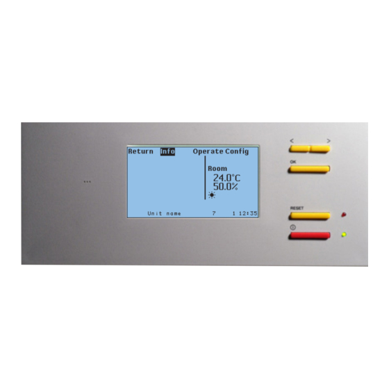
C 7000 I N S T R U C T I O N S F O R A /C U N I T S 2.3 Operational elements - C7000 Display Reset Reset key Alarm On/off On/off key Audible indicator Display Reset key Alarm signals are acknowledged with the reset key. -
Page 10: Controller Start
(Details see on/off protection, on the next page but one). If you press the OK-button when all positions are marked the existing configuration is confirmed after the request and entry of the AT-password. EN/06.2019/G57 © STULZ GmbH – all rights reserved... - Page 11 All active bus participants synchronize their time to this setting. If a WIB8000, in which the time synchronization is enabled, is part of the Stulz bus, all connected C7000ATs and C7000IOCs (by means of E-bus board) take over date and time of the WIB. This also applies to C7000ATs con- nected via an IO bus with an C7000IOC, which is connected with the WIB by an E-bus board.
- Page 12 With the second setting (delay) the window shown beside appears after the on/off key has been pressed. A grey bar diminishes from right to left within 3 seconds. During this time the key must be kept pressed, otherwise the switching operation will not be executed. EN/06.2019/G57 © STULZ GmbH – all rights reserved...
- Page 13 This symbols lights up, when a voltage is detected at the input for UPS operation or if UPS operation is requested by a BMS. This symbols lights up, when the maintenance interval which can be adjusted in the config menu is expired. © STULZ GmbH – all rights reserved EN/06.2019/G57...
- Page 14 When an alarm has occurred the following symbol is displayed in the left bottom corner. Parameter values Instead of numerical values two other displays are possible: 1. ??? - value requested at the C7000IOC, without response yet 2. XXX - component not configured EN/06.2019/G57 © STULZ GmbH – all rights reserved...
- Page 15 The passwords for the "operate" and "config" level are saved on the C7000IOC board. So it is possible for exam- ple to adjust the "operate" password "1234" for a C7000IOC with bus address 3 and the "operate" password "5678" for a C7000IOC with bus address 5. © STULZ GmbH – all rights reserved EN/06.2019/G57...
-
Page 16: Info Menus
When the fire alarm has ended the controller switches to the state, in which it has been before the alarm occured e.g. sequencing stop. 003. automatic alarm reset after limit value excess 004. SATS EN/06.2019/G57 © STULZ GmbH – all rights reserved... - Page 17 Further on in this manual, the menus appear in full view so that all menu items can be explained. © STULZ GmbH – all rights reserved EN/06.2019/G57...
- Page 18 5. The actual value of the supply air humidity sensor (if existant)../Humidity/more 1. The actual value of the outside moisture content sensor (if existant). 2. The actual value of the specific humidity. 3. The setpoint of the specific humidity. EN/06.2019/G57 © STULZ GmbH – all rights reserved...
- Page 19 1. Water temperature at the inlet, circuit 1 2. Water temperature at the outlet, circuit 1 3. Water temperature at the inlet, circuit 2 4. Water temperature at the outlet, circuit 2 Further menu only relevant for the chiller. © STULZ GmbH – all rights reserved EN/06.2019/G57...
- Page 20 The summer operation which has not been caused by alarms but by the excess of the outsi- de temperature limit, is not indicated here. EN/06.2019/G57 © STULZ GmbH – all rights reserved...
- Page 21 Info Components/Cooling The C7000 Advanced gives a detailed representation of the components' operating states. In the window in the left margin the first five menu items lead to submenus. In the last menu item you can read the number of configured external alarms.
- Page 22 The ICC will soon be in eror. See "Working zones ICC for R410a" on the following page. The performance requirement, which is sent by the C7000 to the µPC, is dis- played in the penultimate line. The third line displays the speed requirement calculated from this, that sends the µPC to the inverter.
- Page 23 (oil transport no longer guaranteed) po = suction gas pressure Zone 8 : min. hot gas pressure 8 bar (0°C) passed under Zone 9 : min. suction pressure 3,3 bar (-25°C) passed under © STULZ GmbH – all rights reserved EN/06.2019/G57...
- Page 24 1. Superheat temperature (calculated) 2. Superheat setpoint 3. Opening degree of the valve 4. Reachability of Carel valves 5. Measured suction gas pressure 6. Saturated temperature (calculated) 7. Measured suction gas temperature EN/06.2019/G57 © STULZ GmbH – all rights reserved...
- Page 25 In this menu the on/off state of the pumps is displayed. In case of speed cont- rolled pumps the actual speed is displayed from 0 to 100%../Conden. fan This menu displays the on/off state of the condenser fans and the actual speed from 0 to 100%. © STULZ GmbH – all rights reserved EN/06.2019/G57...
- Page 26 If the actual dewpoint is smaller than the stop dewpoint, dehumi- dification is switched off. Display of the start- and stop dew point, see chapter 5.4.6 -> dew point control. EN/06.2019/G57 © STULZ GmbH – all rights reserved...
- Page 27 Another fan menu displays the pre-filter pressure drops measured by analog pressure sensors and the maximum admissible pressure drops (adjustable). If your A/C unit is equipped with louvers, -1- indicates that the louver is open. © STULZ GmbH – all rights reserved EN/06.2019/G57...
- Page 28 Relay activated* -> component in .../D-OUT D-OUT service 0-20mA, 0-10V corresp. to sensor A-IN 0-4095 type A-OUT 0-4095 0-10V * Exception: When dehumidification is carried out, the relay is not activated../A-IN .../A-OUT EN/06.2019/G57 © STULZ GmbH – all rights reserved...
- Page 29 - edits all values of this day as far as stored. log 1 1 13 - edits the values 1 to 13 counting from the actual point of time. log 1 clear - deletes all stored values. © STULZ GmbH – all rights reserved EN/06.2019/G57...
- Page 30 In another submenu the component runtimes are displayed. Here, the humidifier runtime is displayed. For the components fan, compressor, pump, E-heating and drycooler exist further submenus of the kind as shown left. EN/06.2019/G57 © STULZ GmbH – all rights reserved...
- Page 31 In this menu the software version and the unit type are displayed. The menu point "Option" leads to a submenu, which displays which special software options are active. Here the number of connected EAIO-, EDIO-, EEIO- and EBUS-boards is indicated../options © STULZ GmbH – all rights reserved EN/06.2019/G57...
- Page 32 Timestamp of new time in case of new setting of time Busid changed The bus ID has been changed. backlight auto The display lighting has been switched to automatic mode. backlight on The display lighting has been permanently switched on. EN/06.2019/G57 © STULZ GmbH – all rights reserved...
- Page 33 Uk24mod # not reacha- Faulty Modbus connection from EBUS board to Uk24mod gateway. Uk24mod # MP# error Error in connection with the MP# node No response from MP Faulty connection from Uk24mod to MP#-node. node © STULZ GmbH – all rights reserved EN/06.2019/G57...
-
Page 34: Configuration
EEV "WT too high" alarm Pump 3 Drycooler External components are not part of the unit and must be selected by the installer. Chiller Outside temp. sensor WT: water temperature EN/06.2019/G57 © STULZ GmbH – all rights reserved... - Page 35 1 - The change of parameters becomes effective only by 2 - 0 = no protocol this command. This allows you to change several parame- 1 = SCP (WIB) ters at the same time. 2 = Modbus Slave 16 = Modbus Master © STULZ GmbH – all rights reserved EN/06.2019/G57...
-
Page 36: Loading A New Software
• Press the reset button on the rear side again. • When switching on, ensure that the new version number is correctly displayed. In the service manual G60 the possible applications of the program "C7000-Service.exe" are described. *System requirements: Windows 95/98/NT/2000/ME/XP/Vista/Win7/Win8... -
Page 37: Control Commands - C7000
For example, the parameter which is indicated by can be found in the second column of the fifth line. ➎ © STULZ GmbH – all rights reserved EN/06.2019/G57... -
Page 38: Values
45.1 ➊ ➋ nightsettemp 27.0 humidity setsp 7.0 ➊ ➋ room mintemp temp 15.0 minhumi room humi 3.0 supply maxtemp alarmdelay 4 maxhumi supply alarmdelay 4 All combinations are possible. EN/06.2019/G57 © STULZ GmbH – all rights reserved... - Page 39 The corresponding commands: Values/Air/Temperature load cool 2.5 ➌ integral 10 ➍ mintemp room ➎ maxtemp room commonalarm 1 ➏ mintemp supply alarmprio 8 ➐ All combinations are possible. maxtemp supply ➑ © STULZ GmbH – all rights reserved EN/06.2019/G57...
- Page 40 The corresponding commands: Values/Air/Humidity load humi 10.5 ➌ load dehumi 5.5 ➍ minhumi room ➎ maxhumi room commonalarm 1 ➏ minhumi supply alarmprio 8 ➐ maxhumi supply All combinations are possible. ➑ EN/06.2019/G57 © STULZ GmbH – all rights reserved...
- Page 41 47 limit 5.02 ➎ ➎a maxprealarm 47 delay 30 maxalarm 47 delay 30 ➏ ➏a maxprealarm 47 dout 10 maxalarm 47 dout 10 ➐ ➐a maxprealarm 47 common 1 maxalarm 47 common 1 ➑a ➑ © STULZ GmbH – all rights reserved EN/06.2019/G57...
- Page 42 ➊ The room air control is the standard control. The temperature/humidity sen- sor is placed in the return air intake or in the room and the C7000 controls in accordance with the setpoints set in the menu Config/values/air/tempera- ture or humidity.
- Page 43 You can also enter a gradient factor ➎ for this. The relationship is shown in the graph opposite. 72 74 r.h/% ➍ Actual value Supply air sensor Example (humidity): 49 = 50 + 0.5 • (70 - 72) .../Humidity © STULZ GmbH – all rights reserved EN/06.2019/G57...
- Page 44 If the room humidity (only for rel. humidity) drops below the starting humidity Humidity entered , the supply air humidity setpoint is increased. ➍ 50,5 40 41 r.h/% ➍ Actual value Room air sensor Example: 50.5 = 50 + 0.5 • (40 - 39) EN/06.2019/G57 © STULZ GmbH – all rights reserved...
- Page 45 T/°C Temperature Temperature Tmax Tmax 18,5 18,5 17,5 17,5 Tmin Actual value Actual value T/°C T/°C Room air sensor Room air sensor The corresponding commands: lim mintemp 17.8 ➎ lim maxtemp 21.3 ➏ © STULZ GmbH – all rights reserved EN/06.2019/G57...
- Page 46 ➎ ➄ maxalarm 5 delay 30 maxalarm 12 delay 30 ➏ ➅ maxalarm 5 dout 10 maxalarm 12 dout 10 ➐ ➆ maxalarm 5 common 1 maxalarm 12 common 1 ➑ ➇ EN/06.2019/G57 © STULZ GmbH – all rights reserved...
- Page 47 The alarm delay for high pressure alarm of circuit 1 and 2 can be set in the last line. The corresponding commands: Refrigerant cpset 1 mix 18.2 cpset 1 dx 16.0 lowpressure 2 alarmdelay 5 highpressure 1 alarmdelay 5 circuit 1 © STULZ GmbH – all rights reserved EN/06.2019/G57...
- Page 48 Yet the dynamic condensation pressure control benefits also here. Compressor ZP120KCE operating zone Condensation pressure [bar] condensation pressure setpoint dynamic condensation pressure setpoint [bar] Evaporation pressure EN/06.2019/G57 © STULZ GmbH – all rights reserved...
- Page 49 2 mix 12,3 Setting the fix condensation pressure setpoint for the mix mode in circuit 2 cpset 2 dx 18,4 Setting the fix condensation pressure setpoint for the DX-mode in circuit 2 © STULZ GmbH – all rights reserved EN/06.2019/G57...
- Page 50 The dynamic condensation pressure control has the following advantages in contrast to the control with fixed condensation pressure setpoint: - significantly reduced electrical power consumption at the same cooling capacity - improved pressure control in most operating states by bigger G valve opening EN/06.2019/G57 © STULZ GmbH – all rights reserved...
- Page 51 1 cp1 12,8 lowpressure 1 alarmprio 7 ➊ ➍ cpset 1 ep2 17,0 highpressure 1 din 4 ➊ ➎ cpset 1 cp2 32,6 highpressure 1 commonalarm 1 ➊ ➏ highpressure 1 alarmprio 8 ➊ © STULZ GmbH – all rights reserved EN/06.2019/G57...
- Page 52 DX setpoint [bar] Copeland ZP83KCE-TFD R410A Copeland ZP72KCE-TFD R410A Copeland ZP61KCE-TFD R410A Copeland ZP54KCE-TFD R410A Copeland ZP42KCE-TFD R410A 16,5 16,5 Copeland ZP36KCE-TFD R410A Copeland ZP31KCE-TFD R410A Copeland ZP29KCE-TFD R410A Copeland ZP24KCE-TFD R410A EN/06.2019/G57 © STULZ GmbH – all rights reserved...
- Page 53 DX-operation or to disable CW-operation CW-off = 0 Switching back to the original priority can only be done by an alarm reset. The corresponding commands: coolingprio 1 0: GE 1: CW 2: DX © STULZ GmbH – all rights reserved EN/06.2019/G57...
- Page 54 The parameter "OTE" in the fifth line is customer specific, for standard units ➎ the setting must be "STULZ". For enabling the OTE software this parameter is set to "OTE". With the parameter in the sixth line you can determine whether the unit may ➏...
- Page 55 = 1 sec. = 10 • 0,3 • 1 • 0,333 = 1 (opening degree in %) I factor: = 10 after 5 sec.: component depen- dant constant: = 5% = 0,333 © STULZ GmbH – all rights reserved EN/06.2019/G57...
- Page 56 = 0,3 K at the moment t For calculating the output variable the single parts are added: j = j j = 3 + 5 + (- 2) j = 6% EN/06.2019/G57 © STULZ GmbH – all rights reserved...
- Page 57 The default settings for the G valve are chosen in such a way that they work for possibly all operating states in a satisfying way. Optimizations on one side (control speed) can easily entail a significantly worse behaviour on the other side (control stability and accuracy). © STULZ GmbH – all rights reserved EN/06.2019/G57...
-
Page 58: Components
1 alarmdelaybr 8 ➋ sensor 1 trim 22.3 If, instead of a temperature, the ➌ expression "reset" is entered, the sensor calibration is deleted. Insert here the value of the reference measuring instrument. EN/06.2019/G57 © STULZ GmbH – all rights reserved... - Page 59 1 commonalarmbr 1 ➍ ➒ sensor 1 minout 0.0 sensor 1 alarmpriobr 3 ➎ ➒ sensor 1 maxout 9.0 sensor 1 bms 0 ➎ ➓ sensor 1 minmeas -20.0 ➏ sensor 1 maxmeas 40.0 ➏ © STULZ GmbH – all rights reserved EN/06.2019/G57...
- Page 60 Water temperature 1 is always the temperature for the CW-valve which is acti- ve, when no change-over has taken place (no voltage at DIN 3). Water temperature 2 is the temperature for the second CW-valve, which is active after a change-over. EN/06.2019/G57 © STULZ GmbH – all rights reserved...
-
Page 61: Refrigerant Circuit, Standard
The corresponding commands: comp 1 startsum 0.6 winterdelay 180 ➊ ➎ comp 1 startwin 1.2 ➊ comp 1 hyssum 0.7 ➋ comp 1 hyswin 0.7 ➋ comp 1 pause 180 ➌ © STULZ GmbH – all rights reserved EN/06.2019/G57... - Page 62 A high pressure alarm is evaluated for each refrigerant circuit instead. - see menu Config/values/refrigerant/HP management The corresponding commands: comp 1 conf 1 ➊ comp 1 dout 3 ➋ comp 1 limit 1.5 ➌ comp 1 hys 0.5 ➍ EN/06.2019/G57 © STULZ GmbH – all rights reserved...
- Page 63 ➎ pressure range. The corresponding commands: comp 1 wac epmintries 6 ➎ comp 1 wac epmin 4.6 ➎a comp 1 wac epminint 2 ➎b © STULZ GmbH – all rights reserved EN/06.2019/G57...
- Page 64 Such an interconnection also exists between compressor 2, 4 and 6. The corresponding commands: comp 1 wac cpmaxtries 3 ➏ comp 1 wac cpmax 21 ➏a comp 1 wac cpmaxint 2 ➏b comp 1 wac hpmode 1 ➐ EN/06.2019/G57 © STULZ GmbH – all rights reserved...
- Page 65 It is also possible to block the start of on/off compressors by a digital input. The digital input can be adjusted via the following command: comp 1 blockdin 9 The corresponding commands: dxstart quickstart 1 ➊ dxstart delaybyfc 180 ➋ © STULZ GmbH – all rights reserved EN/06.2019/G57...
- Page 66 Compressor, external Components/Cooling Compressor/more/more In this menu you can set parameters which serve exclusively to configure an external compressor. These parameters are explained in detail in the controller manual for the EC tower. EN/06.2019/G57 © STULZ GmbH – all rights reserved...
- Page 67 ICC are kept. ➊ The ICC control unit communicates with the C7000 by the RS485 component bus. The precondition for this is the identification by a global address. In the second line you can set a global address for the ICC.
- Page 68 By these commands you can limit the power of the speed icc 1 pmax 80 controlled compressor. The minimum/maximum power is entered in %. icc 1 cmswd 20 for the EC compressor you can set a minimum speed for dehumidification. EN/06.2019/G57 © STULZ GmbH – all rights reserved...
- Page 69 Then the speed of the first compressor is controlled according to the cooling requirement. The start values and hysteresises in the compressor menu are not evaluated by 16,7% the control. © STULZ GmbH – all rights reserved EN/06.2019/G57...
- Page 70 (this is the pre-condition for the compressor start), the com- pressor may start. The corresponding commands: icc 1 pet 6 ➊ icc 1 peog 50 ➋ icc 1 pep 20 ➌ EN/06.2019/G57 © STULZ GmbH – all rights reserved...
- Page 71 18: R423A 18: Danfoss ETS 400 18: remote 0..30 barg 19: R407A 19: 2 Carel EXV swit- 19: remote 0..44,8 barg 20: R427A ched in parallel 20: ext. signal 4..20 mA 20: Sporlan SER(I) © STULZ GmbH – all rights reserved EN/06.2019/G57...
- Page 72 1 commonalarmpress 0 ➎ Setting of the network address only by eev 1 commonalarmtemp 1 ➏a C7000 command: eev 1 commonalarmmotor 1 ➐a eev 1 id 198 eev 1 commonalarmna 1 ➑a EN/06.2019/G57 © STULZ GmbH – all rights reserved...
-
Page 73: Refrigerant Circuit, Optional Components
0,5 K. The corresponding commands: Operate Config suctionv 1 start 0.2 suctionv 1 conf 1 ➊ ➊ suctionv 1 grad 0.9 suctionv 1 aout 3 ➋ ➋ suctionv 1 min 20 ➌ © STULZ GmbH – all rights reserved EN/06.2019/G57... - Page 74 ➒ ➋ hgbp 1 concyc 3 ➌ hgbp 1 pfact 5 ➍ hgbp 1 ifact 5 ➎ hgbp 1 dfact 5 ➏ hgbp 1 pretime 10 ➐ hgbp 1 preopen 40 ➑ EN/06.2019/G57 © STULZ GmbH – all rights reserved...
- Page 75 If condensers with proportionally controlled fans are used for the condensation of the refrigerant, these can be controlled by the C7000 using a PID control. By setting the parameter "ACTIVE" on 1 in the first line you add a condenser fan to the configuration ➊...
- Page 76 ➋ cond 1 pid cd 0 ➌ cond 1 concyc 1 ➍ cond 1 maxc 10 ➎ cond 1 min 10 ➏ cond 1 pretime 10 ➐ cond 1 prespeed 100 ➑ EN/06.2019/G57 © STULZ GmbH – all rights reserved...
-
Page 77: Cooling Water Circuit, Internal Components
1 conf 1 ➊ gvalve 1 aout 4 ➋ gvalve 1 pretime 30 ➌ gvalve 1 preopen 100 ➍ gvalve 1 opensp 70 ➎ gvalve 1 ows 31 ➏ gvalve 1 bias 1.4 ➐ © STULZ GmbH – all rights reserved EN/06.2019/G57... - Page 78 1 min 20 ➊ ➎ gvalve 1 pid ki 4 gvalve 1 minstart 20 ➋ ➏ gvalve 1 pid kd 2 gvalve 1 mingradient 1 ➌ ➐ gvalve 1 maxc 2 ➍ EN/06.2019/G57 © STULZ GmbH – all rights reserved...
- Page 79 This signal can be used to control an external chiller. The corresponding commands: gecwv 1 start 0.2 ➊ gecwv 1 off 22 ➋ gecwv 1 offrel 2 ➌ gecwv 1 dout 2 ➍ © STULZ GmbH – all rights reserved EN/06.2019/G57...
- Page 80 1 bias 1.4 ➍ gecwv 1 pid kp 50 ➎ gecwv 1 pid ki 4 ➏ gecwv 1 pid kd 2 ➐ gecwv 1 spclose 1 ➑ gecwv 1 heating 1 ➒ EN/06.2019/G57 © STULZ GmbH – all rights reserved...
- Page 81 GE/CW valve is opened 100% and the chillersaver signal is switched off. (0% = 0V = highest chiller WT setpoint). The corresponding commands: cw sav100 30 ➐ cw savstart 0.2 ➑ cw savend 1.4 ➒ © STULZ GmbH – all rights reserved EN/06.2019/G57...
- Page 82 In additional operation the chillersaver signal is not available (0% = 0V = highest chiller WT setpoint). In changeover operation the chillersaver signal is not available, when a changeover takes place (0% = 0V). EN/06.2019/G57 © STULZ GmbH – all rights reserved...
- Page 83 10 ➋ ➋ cw savaout 5 cw opensp 70 ➌ 0: separate ➌ cw oper 0 cw maxmix 65 ➍ ➍ 1: added cw compoff 1 ➎ 2: DFC 3: DTC © STULZ GmbH – all rights reserved EN/06.2019/G57...
-
Page 84: Cooling Water Circuit, External Components
1 hys 3.0 ➌ ➐ ➋ drycool 1 maxc 4 drycool 1 alarm 5 drycool 1 alarmdelay 3 ➍ ➑ ➌ drycool 1 commonalarm 1 ➍ drycool 1 alarmprio 3 ➍ EN/06.2019/G57 © STULZ GmbH – all rights reserved... - Page 85 DFC control. For this a separate ➍ manual (GE systems) exists. Alarm parameter: Alarm delay ➎ The corresponding commands: pump 1 start 0.1 ➊ pump 1 hys 0.7 ➋ pump 1 alarmdelay 6 ➎ © STULZ GmbH – all rights reserved EN/06.2019/G57...
- Page 86 1 partpump 1 pump 1 type 2 ➋ ➃ pump 1 dout 3 ➌ pump 1 aout 4 ➍ pump 1 alarm 3 ➎ pump 1 commonalarm 0 ➏ pump 1 alarmprio 3 ➐ EN/06.2019/G57 © STULZ GmbH – all rights reserved...
-
Page 87: Air Circuit, Internal Standard Components
24, 25 or 26. The corresponding commands: fan 1 start 3 ➊ fan 1 speed 15 ➋ fan 1 alarmdelay 6 ➌ fan 1 filteralarmdelay 6 ➍ fan 1 filterpress 70 ➎ © STULZ GmbH – all rights reserved EN/06.2019/G57... - Page 88 1 nmincw 40 ➏ ➏ fan 1 fact 2 fan 1 nmax 85 ➐ ➐ fan 1 nmaxcw 90 ➑ Type 1: On/off control fan 1 nmaxefc 85 ➒ Type 2: Proportional control EN/06.2019/G57 © STULZ GmbH – all rights reserved...
- Page 89 The corresponding commands: fan 1 alarm 2 ➊ fan 1 commonalarm 1 ➋ fan 1 alarmprio 3 ➌ fan 1 filteralarm 6 ➍ fan 1 commonalarmfi 1 ➎ fan 1 filteralarmprio 4 ➏ © STULZ GmbH – all rights reserved EN/06.2019/G57...
- Page 90 1 pre 15 ➋ fan 1 after 20 ➌ fan 1 redtime 30 ➍ fan 1 redspeed 20 ➍ fan 1 filteroffset 15 ➎ fan 1 dehumtime 26 ➏ fan 1 dehum 25 ➏ EN/06.2019/G57 © STULZ GmbH – all rights reserved...
- Page 91 The corresponding commands: fan 1 emerstart 0.7 ➑ fan 1 emernmax 95 ➑ fan 1 emerend 2.0 ➒ fan 1 cestop 1 ➓ fan 1 dtctype 0 fan 1 dehumisat 6.4 fan 1 dehumisatsp 6.5 © STULZ GmbH – all rights reserved EN/06.2019/G57...
- Page 92 = 90% - 50% * 90% because of dehumidific. n = 45% n = 60% SPEED be made due to the non-re- quest of climatic functions within the REDUCE TIME ? Legend: next step EN/06.2019/G57 © STULZ GmbH – all rights reserved...
- Page 93 If this is insufficient, the fan speed is reduced additionally after a time delay. In A/C units with two refrigerant circuits only one compressor is used for the dehumidification. © STULZ GmbH – all rights reserved EN/06.2019/G57...
- Page 94 - Closes the dehumidifica- - Reduces the fan speed to the EEV - Reduces the tion valve - Reduces the fan speed after the fan speed lapse of "Time until dehumidifiction reduction" EN/06.2019/G57 © STULZ GmbH – all rights reserved...
- Page 95 10 14 20 24 °C water temp. The corresponding commands: dehumi start 7.0 ➊ dehumi startsp 8.0 ➊ dehumi hys 7.0 ➋ dehumi hyssp 2.0 ➋ dehumi min 4 ➌ dehumi max 10 ➍ © STULZ GmbH – all rights reserved EN/06.2019/G57...
- Page 96 1 ➁ dehumi dout 12 ➂ dehumi type 0 ➃ Type 0: dehumidification by relative humidity dehumi stop 2.0 ➄ Type 1: dew point control Type 2: dehumidification by specific humidity EN/06.2019/G57 © STULZ GmbH – all rights reserved...
- Page 97 If the actual dewpoint is smaller than the start dewpoint, humidification is switched on. If the actual dewpoint is bigger than the stop dewpoint, humidifi- cation is switched off. DP/°C Start DP Stop DP © STULZ GmbH – all rights reserved EN/06.2019/G57...
-
Page 98: Air Circuit, Internal Optional Components
1 hys 9.0 ➋ humi 2 hyssp 0.5 ➋ humi 1 grad 10.0 ➌ humi 2 bandsp 2.0 ➌ humi 1 alarmdelay 6 ➍ humi 1 alarmdelay5 6 ➎ humi 1 alarmdelay20 6 ➏ EN/06.2019/G57 © STULZ GmbH – all rights reserved... - Page 99 1 alarmprio5 5 ➍ ➐ humi 1 confcon 1 humi 1 alarm20 7 ➎ ➑ humi 1 alarm 7 humi 1 commonalarm20 1 ➏ ➑ humi 1 commonalarm 1 humi 1 alarmprio20 5 ➏ ➑ © STULZ GmbH – all rights reserved EN/06.2019/G57...
- Page 100 ➊ eheat 1 hys 0.7 gasheat hys 0.6 pwwheat hys 0.6 ➋ ➋ ➋ eheat 1 grad 0.9 gasheat alarmdelay 5 pwwheat grad 0.5 ➌ ➌ ➌ eheat 1 alarmdelay 3 ➍ EN/06.2019/G57 © STULZ GmbH – all rights reserved...
- Page 101 1 aout 8 eheat 1 alarm 7 ➍ ➍ ➍ gasheat 1 alarmprio 3 eheat 1 commonalarm 1 ➎ ➎ Type 1: On/off control eheat 1 alarmprio 3 ➏ Type 2: Proportional control © STULZ GmbH – all rights reserved EN/06.2019/G57...
-
Page 102: Air Circuit, External Optional Components
With the parameter "D-OUT" you determine a digital output for the louver. ➋ The corresponding commands: Operate Config louver 1 pretime 100 louver 1 conf 1 ➎ ➊ louver 1 dout 11 ➋ EN/06.2019/G57 © STULZ GmbH – all rights reserved... -
Page 103: Auxiliary Ports
17 ups din 13 ➋ ➋ fcm dout 4 cwoff din 16 ➌ ➌ ➍ bmsstop 1 dout 5 ➎ localstop dout 8 ➏ onoff dout 1 ➐ econ dout 3 ➑ © STULZ GmbH – all rights reserved EN/06.2019/G57... - Page 104 10V will be output. ➌ The corresponding commands: valout 1 use 2 ➊ valout 1 aout 6 ➋ valout 1 min 5.0 ➌ valout 1 max 35.3 ➌ EN/06.2019/G57 © STULZ GmbH – all rights reserved...
-
Page 105: Statistics
The first numeral designates the number of ➊ log 1 type 2 the data logger (1 or 2). ➋ The second numeral stands for: - the cycle in minutes - the measure values listed left top. © STULZ GmbH – all rights reserved EN/06.2019/G57... - Page 106 1 runtimes in the new controller. By "1" you con- ➎ ➎ drycool 1 runtime 0 In order to reset a runtime set runtime to "0". firm the executed ➏ maintenance. EN/06.2019/G57 © STULZ GmbH – all rights reserved...
- Page 107 1 ➋ ➏ 2: Modbus dplist 1 ➌ loaddefault ➍ 0: none 1: Classic 2: Full The configuration for customer specific data point lists can contain 3: Custom 256 entries. © STULZ GmbH – all rights reserved EN/06.2019/G57...
-
Page 108: Special Operation Modes
1 = A/C unit on with setpoint 1 we = wednesday 2 = etc. 2 = A/C unit on with setpoint 2 th = thursday fr = friday sa = saturday su = sunday EN/06.2019/G57 © STULZ GmbH – all rights reserved... -
Page 109: Zone Control
(GEoff parameter), although the system water temperature is actually appropriate for it. To avoid this problem, you can set a delay time for the evaluation of the average value, in which the heat accumulation in the standby unit can dissipate. © STULZ GmbH – all rights reserved EN/06.2019/G57... - Page 110 "1". The existence of standby units in a zone increase the air conditioning operating security and provides the possibility to replace defective units by standby units. Config/Zone/more/more (Z2a) EN/06.2019/G57 © STULZ GmbH – all rights reserved...
- Page 111 35.reserved for CyberCool2 36.reserved for CyberCool2 37.Watertemp. in 1 high 38.Watertemp. in 2 high 39.Watertemp. in 1 & 2 high 40.Watertemp. in 1 low 41.Watertemp. in 2 low 42.Watertemp. in 1 & 2 low © STULZ GmbH – all rights reserved EN/06.2019/G57...
- Page 112 T in the shape of a temperature difference. Setting Command: load cool 2.5 "0" disables the additional capacity function. When the temperature sinks again, the additional capacity unit is switched off with a hysteresis of 1K. EN/06.2019/G57 © STULZ GmbH – all rights reserved...
- Page 113 The additional capacity unit must be set as standby unit and must be assigned to a zone. Moreover the corres- ponding parameter (temperature or humidity) "Overload" must have a value different from zero. © STULZ GmbH – all rights reserved EN/06.2019/G57...
-
Page 114: Sequencing
Unit 02 Unit 04 Unit 05 Unit 01 Unit 03 Unit 07 Stand Stand Stand Stand Unit 06 Unit 09 Unit 10 Unit 08 Unit 11 Unit 14 Cycle 2 Cycle 2 EN/06.2019/G57 © STULZ GmbH – all rights reserved... -
Page 115: Cw Standby Management
"f" units have failed. This correlation is represented by the following formula. n > f • ( 100 - nMax © STULZ GmbH – all rights reserved EN/06.2019/G57... -
Page 116: Zone For Dfc Control
DFC operation is enabled. water return air water rel. Some parameters as sequencing cycle and standby state are only operative in DX mode. DFC control is described in detail in the manual "GE systems". EN/06.2019/G57 © STULZ GmbH – all rights reserved... - Page 117 1 sbaverage 0 ➋ ➒ zone 1 emernum 3 ➌ zone 1 emertemp 15.7 ➍ zone 1 cwmode 1 ➎ zone 1 test 1 en- (1) or disables (0) test sequencing ➏ © STULZ GmbH – all rights reserved EN/06.2019/G57...
- Page 118 The corresponding commands: zone 1 gestart 18.0 ➊ zone 1 gestartrel 2,0 ➋ zone 1 gehys 2.0 ➌ zone 1 gewstart 12.0 ➍ zone 1 gewstartrel 2,0 ➎ zone 1 gewhys 2.0 ➏ EN/06.2019/G57 © STULZ GmbH – all rights reserved...
- Page 119 0 means normal operation, 1 means standby operation. as above item ➌ The corresponding commands: zone 1 avgdelay 60 ➐ zone 1 unit 3 0 puts unit 3 into standby ➑ zone 1 unit 3 1 switches unit 3 on © STULZ GmbH – all rights reserved EN/06.2019/G57...
- Page 120 3 - max, biggest value in the zone zone 1 alarm 2 0 deletes valid alarm 2 zone 1 alarm 2 1 adds alarm 2 as valid alarm zone 1 alarm h displays list of all available alarms EN/06.2019/G57 © STULZ GmbH – all rights reserved...
-
Page 121: Ecocool
The return air sensor must be installed out of the A/C unit in the room. Installation example Fresh air louver Exhaust air Circulating air louver Exhaust air louver Fresh air Circulating air Thermical load Room air External sensor temp. sensor A/C unit (Downflow) © STULZ GmbH – all rights reserved EN/06.2019/G57... - Page 122 After the delay (during which the unit is in DX/CW mode) has elapsed, free cooling can be enabled according to the conditions listed on the next page. ➌ eco delay 10 EN/06.2019/G57 © STULZ GmbH – all rights reserved...
- Page 123 1 hys 1,0 Hysteresis Hysteresis dehumi start 10,0 dehumi hys 1,0 Enabling condition ➋ Hysteresis ➊ Anti-freeze ➎ temp. Start temp. RT: Room air temperature OT: Outside air temperature RT – OT ➌ © STULZ GmbH – all rights reserved EN/06.2019/G57...
- Page 124 Fan speed table Fan speed Stand alone Zone oper. Basic speed maxZone ➋ ➊ Room Maximum speed 100% temp. SP: Room temperature setpoint eco lv start 0.1 ➊ eco lv grad 0.6 ➋ EN/06.2019/G57 © STULZ GmbH – all rights reserved...
- Page 125 – SP Example: basic speed = nmax = 70%, Max speed = 100%, SP = 24°C, RT = 25°C results in a control factor of 30. Fan speed EFC mode Max.speed basic speed © STULZ GmbH – all rights reserved EN/06.2019/G57...
- Page 126 24,4 24,7 Compressor start temperature DX Mode DX mode is always chosen when at least one of the general enabling conditions for free cooling does not exist anymore. see Fan speed table EN/06.2019/G57 © STULZ GmbH – all rights reserved...
- Page 127 = max. speed (with RT = RT 3 MIX -> EFC if RT = SP + comp.-start temp – hysteresis 4 EFC -> FC if OT < ECO start temp. (or RT < SP) © STULZ GmbH – all rights reserved EN/06.2019/G57...
- Page 128 Louver opening according to Fresh air/ FC/EFC mode exhaust air louver 100% Circulating air louver Louver opening according to FC/EFC mode RT – OT RT: Room air temperature ➍ OT: Outside air temperature EN/06.2019/G57 © STULZ GmbH – all rights reserved...
- Page 129 (set parameter filter alarmact 1 ➌ "action" on "1"). ➌ filter alarm 1 ➍ filter alarmprio 19 ➎ filter alarmdelay 5 ➏ © STULZ GmbH – all rights reserved EN/06.2019/G57...
-
Page 130: Operation Modes For Cw2 Units
C4 of the Config level and is output by a freely adjustable digital out- put (menu C2, parameter D-OUT). If a dehumidification request exists, the active valve will be opened 100% to provide maximum cooling capacity for dehumidification. EN/06.2019/G57 © STULZ GmbH – all rights reserved... - Page 131 Using 2-way valves, the conditions 4 and 5 for the changeover must be avoided. This can be achieved by setting the "GE-off" parameter sufficiently high and by setting the parameter "Close over SP" to 0. © STULZ GmbH – all rights reserved EN/06.2019/G57...
- Page 132 3.0 ➋ Setpoint (return air) NOTICE If at least one of the values (Return air temperature or water inlet temperature) can- not be measured, CW valve 1 will be opened 100%. EN/06.2019/G57 © STULZ GmbH – all rights reserved...
-
Page 133: Differential Pressure Control
All speed increases or reductions for the fan are put out of force. After the unit stop the fan runs during an overrun time, which serves to reject hot or cold air in the unit. © STULZ GmbH – all rights reserved EN/06.2019/G57... - Page 134 In the menu D8 of the Info level you can read and compare the actu- al and set value of the air pressure in the raised floor or cold aisle compartment. Config/Components/Air/ Fan/Alarm (D7) Info/Values/Air/Pressure (D8) EN/06.2019/G57 © STULZ GmbH – all rights reserved...
-
Page 135: Supply Air Pressure Standby Management (Sapsm)
The SAPSM is activated by the special software option 7. Command: option 7 1 20 s Additionally the SAPSM delay must be set on a value bigger than zero. Command: sapsmdelay 20 (in seconds) © STULZ GmbH – all rights reserved EN/06.2019/G57... - Page 136 SAPSM delay has elapsed, is switched off. supply air pressure Setpoint time SAPSM delay fan speed standby unit SAPSM delay EN/06.2019/G57 © STULZ GmbH – all rights reserved...
- Page 137 Otherwise the state is determined by the actual operating mode. If e-g- free cooling in the frame of DFC con- trol is not possible anymore, the standby units are switched off. In the DX mode the control tries to match the supply air pressure setpoint by raising the fan speed. © STULZ GmbH – all rights reserved EN/06.2019/G57...
- Page 138 A standby unit which has been stopped due to an excessively high supply pressure, is restarted only, if the supply air pressure is too low, even if free cooling is possible (and standby units would be normally switched on, as usual in DFC control or CW standby management). EN/06.2019/G57 © STULZ GmbH – all rights reserved...
- Page 139 SAPSM delay = 240 s Hint: Set the fan over-runtime and the pre-time of the louver on the same values for each unit in the zone. Set the SAPSM delay twice as big as the fan over-runtime. © STULZ GmbH – all rights reserved EN/06.2019/G57...
-
Page 140: Sapsm And No Supply Air Pressure Control In Case Of Sensor Failure
Order of priorities concerning the fan Control according to: 1 = fixed speed (lowest) 2 = CW-standby-management 3 = Ecocool 4 = DFC 5 = temperature difference 6 = supply air pressure (highest) EN/06.2019/G57 © STULZ GmbH – all rights reserved... -
Page 141: Differential Temperature Control
1, 3, 14 - 17, which then releases the alarm "Sensor # excess". To avoid this alarm, the admissible tolerance must be raised or set to 0%. At 0% the alarm is not evaluated. © STULZ GmbH – all rights reserved EN/06.2019/G57... - Page 142 Command: We recommend, not to use the following fan functions with the differen- tial temperature control: - reduction according to temperature - reduction according to time - dehumidification speed - emergency operation EN/06.2019/G57 © STULZ GmbH – all rights reserved...
- Page 143 Return air temp. fan 1 dtcstart 0,2 ➊ fan 1 dtcband 1 ➋ Setpoint (return air or supply air) fan 1 min 70 ➌ fan 1 nmax 95 ➍ fan 1 dtctype 1 ➎ © STULZ GmbH – all rights reserved EN/06.2019/G57...
- Page 144 There are m units in a zone. If all m units are running, the minimum speed of each fan in each unit is n . If only max Zone units are in operation (due to the failure of one unit), the minimum speed of each fan is n EN/06.2019/G57 © STULZ GmbH – all rights reserved...
-
Page 145: Summer-/Winter Operation
➋ Config Components Aux. Ports/Aux. Ports In this menu in the second line you can adjust the digital output for the win- termode. The wintermode signal can be forwarded to a BMS system. © STULZ GmbH – all rights reserved EN/06.2019/G57... -
Page 146: Manual Operation
6.9 Manual Operation Components Manual operation When manual operation is used the C7000 control is put out of force. The manual operation menu consists of two columns of parameters which are decisive for the operation. In the first column (titled EN.) you enable the manual operation of the listed component by setting the parameter to "1". -
Page 147: Ups Operation
Take care of selecting the limitation by an absolute GEoff value in GE units. The corresponding commands: ups fan 1 ➊ ups cool 1 ➋ ups heat 0 ➌ ups humi 0 ➍ ups dehumi 0 ➎ © STULZ GmbH – all rights reserved EN/06.2019/G57... -
Page 148: Act - Adaptive Cooling Technology
(command: act time <1..255>). The control mode is set by the BMS or can be adjusted at the C7000 controller (command: act control <1..4>). The control mode adjusted in the C7000IOC, which is active at ACT activation, is not taken. -
Page 149: Calculation Of The Air Volume Flow
The calculated air volume flow can be output by an analog output. See menu Config/components/aux. ports/A-OUT. The sensor purpose which must be chosen is "air volume flow" (com- mand: valout # use 37). © STULZ GmbH – all rights reserved EN/06.2019/G57... -
Page 150: Power Indication
3. the cursor is now in the middle column on a case which indicates "return". By the selector key you can choose between the options "reset" and "return". 4. confim selected function by the OK-key. EN/06.2019/G57 © STULZ GmbH – all rights reserved... -
Page 151: Control Of A Uk24Mod Gateway
Find out the Modbus ID by the setting of the dip switches on the Uk24mod gateway. 8 dip switches, by which the Modbus ID is set in binary form, are located under the front cover. © STULZ GmbH – all rights reserved EN/06.2019/G57... - Page 152 ( 10) serial number 4th.part...:108 ( 11) Drive type.......:5 (controller volume flow VAV/EPIV) ( 12) Time monitoring....:0 s ( 13) Min......:0.00 % ( 14) Max......:100.00 % ( 15) Absolute volume flow.....:0 ( 16) Nominal volume flow....:288 EN/06.2019/G57 © STULZ GmbH – all rights reserved...
-
Page 153: Special Software Option For Cyberlab Units
To also dehumidify efficiently with low heat loads (compressor power) the compressor speed is increased during dehumidification. To maintain the temperature the air must be reheated. If the electric reheat does not suffice, the hotgas reheat is additionally switched on due to its start value. © STULZ GmbH – all rights reserved EN/06.2019/G57... -
Page 154: Bus Communication
RS-485 I/O-Bus Up to 20 C7000IOCs can be linked in a C7000 I/O bus system. The C7000 AT Box which serves to configure or to operate the A/C units equipped with an C7000IOC also takes part in the RS-485 bus. The C7000Dis- play neither participates in the bus nor occupies a bus position. -
Page 155: System Architecture With The C7000At
The maximum configuration in relation to the operational facilities and the number of A/C units consists of 10 A/C units with a C7000IOC and a C7000AT which also results in 20 bus sharing elements. © STULZ GmbH – all rights reserved EN/06.2019/G57... -
Page 156: Bus Layout
7.3 Bus Layout 7.3.1 General The IO bus consists of maximum 20 participants. In case of the C7000 system only C7000IOC or C7000AT bus participants can be in the IO bus. Each bus participant has its own IO bus address which must only appear once in the data bus. -
Page 157: Preparation Before Installation
0 as standard. On a C7000AT the bus address is adjusted in the placement view. in short: 1. connect units by bus lines 2. set bus terminations (beginning/end) 3. adjust bus-IDs 4. confirm bus configuration © STULZ GmbH – all rights reserved EN/06.2019/G57... - Page 158 0 does not exist anymore. The addresses of all other participants are not affected by this. How to get to the placement view and how to confirm the configuration, see chapter 3, page 10. EN/06.2019/G57 © STULZ GmbH – all rights reserved...
-
Page 159: Bus Overview
When the disconnected unit is switched on again, the bus error is automatically deleted at all bus participants. A bus error can also be deleted by inputting the command " iobusok " at a C7000IOC or a C7000AT. © STULZ GmbH – all rights reserved EN/06.2019/G57... -
Page 160: Special Cases
IO-Controller 100% IO-Controller 100% IO-Controller 100% IO-Controller unknown unknown unknown unknown unknown unknown unknown unknown AdvancedTerminal AdvancedTerminal unknown error unknown error ERROR IN THE BUS CONFIGURATION DETECTED. EN/06.2019/G57 © STULZ GmbH – all rights reserved... - Page 161 As soon as the communication on the bus starts, one of them detects that the address 19 has been assigned twice and performs a deactivation. The result is that only one bus participant with the same address is active after a short time. © STULZ GmbH – all rights reserved EN/06.2019/G57...
- Page 162 "ME". If the unit is a C7000IOC the error LED on the board flashes, the state of the bus configuration can then be requested by using the service port. EN/06.2019/G57 © STULZ GmbH – all rights reserved...
-
Page 163: Alarm Treatment
Alarms can either be reset in the standard window for each single unit or in the bus configuration overview by marking all bus participants for all units. C7000IOC Reset the alarms for one unit with the command " alarmreset " or " ". © STULZ GmbH – all rights reserved EN/06.2019/G57... -
Page 164: Configuration Of External And Unit Alarms
1 alarmprio 9 Config fire ➎ ➊ din 15 exalarmin 1 alarmdelay 6 water ➏ ➋ commonalarm 1 flow ➌ alarmprio 8 phase ➍ commonalarm 1 busalarm ➎ alarmprio 8 adrconflict ➏ EN/06.2019/G57 © STULZ GmbH – all rights reserved... -
Page 165: Alarm Texts
* the corresponding alarm can be configured to release a common alarm which can control further equipment by a digital output. ** the alarm text can be configured. Except the alarm "UNRELIABLE EEV" all alarms must be manually reset on the C7000AT or C7000IOC. © STULZ GmbH – all rights reserved EN/06.2019/G57... - Page 166 (180 seconds, pre-configured in the µPC) or after the minimum restart cycle (360 seconds, pre-configured in the µPC). The "Discharge temperature alarm" is not reset by the µPC and must be manually be reset. EN/06.2019/G57 © STULZ GmbH – all rights reserved...
-
Page 167: Alarm Texts In The Case Of Hardware Errors
Nr. 09 Cannot select extension port Nr. 10 Analoge extension card error Nr. 11 Analoge extension card: cannot read input Nr. 12 Analoge extension card: cannot set output Nr. 13 Ext ID:Set IO-ports © STULZ GmbH – all rights reserved EN/06.2019/G57... -
Page 168: Troubleshooting
IOC board. • Carefully pry the RTC module with an IC extractor from the socket. • Insert the new RTC module and observe the polarity (pin1 to pin 1). IC extractor EN/06.2019/G57 © STULZ GmbH – all rights reserved... - Page 169 • Mount the acrylic glass pane onto the board. • Close the A/C unit. • Switch on the A/C unit. • Set the correct time and date. • Check whether bus address and BMS specific settings are correct. © STULZ GmbH – all rights reserved EN/06.2019/G57...
-
Page 170: Hardware Components
JP 2 3 4 5 green LEDs for red LEDs for RS485 busses on a plugged EBUS extension digital inputs 1-11 digital outputs 1-7 board. EN/06.2019/G57 © STULZ GmbH – all rights reserved... - Page 171 SUB-D 15 Dout 5 (COM) SUB-D 15 Dout 5 (NC) SUB-D 15 Dout 6 (NO) SUB-D 15 Dout 6 (COM) SUB-D 9 Dout 6 (NC) Dout 7 (NO) Dout 7 (COM) Dout 7 (NC) © STULZ GmbH – all rights reserved EN/06.2019/G57...
-
Page 172: Edio - Extension Board For Digital In- And Outputs
The function of the digital outputs is displayed by red LEDs: relay active OFF: relay passive enlarged section for onboard LEDs green LEDs for red LEDs for digital inputs 12-19 digital outputs 8-13 of the first EDIO-board EN/06.2019/G57 © STULZ GmbH – all rights reserved... - Page 173 Dout 11 (COM) Dout 11 (NC) Dout 12 (NO) Dout 12 (COM) Dout 12 (NC) Dout 13 (NO) Dout 13 (COM) Dout 13 (NC) PWM1 PWM2 SUB-D 15 Pins 31 to 40 are not assigned. © STULZ GmbH – all rights reserved EN/06.2019/G57...
-
Page 174: Eaio - Extension Board For Analog In- And Outputs
302. Jumper 302 must be set on position 2-3. Jumper setting corresp. Jumper 102-402 Jumper input (enlarged section) AIN 6 AIN 9 AIN 7 AIN 8 AIN 8 AIN 9 0-10V AIN 7 4-20mA AIN 6 EN/06.2019/G57 © STULZ GmbH – all rights reserved... - Page 175 Aout 5 The jumpers 102, 202, 302 and 402 must be set as described on Aout 6 the precedent page. Aout 7 Aout 8 SUB-D 15 Pins 25 to 40 are not assigned. © STULZ GmbH – all rights reserved EN/06.2019/G57...
-
Page 176: Ebus-Extension Board For Rs485 Bus
IO controller Note: Remove jumper 8 on the IOC board to use the EBUS port 2. Remove jumper 9 on the IOC board to use the EBUS port 3. EN/06.2019/G57 © STULZ GmbH – all rights reserved... -
Page 177: Driver Module For Electronic Expansion Valve Evd
Sensor 3, suction gas pressure circuit 2 Network address (pre-set 198) Sensor 4, suction gas temperature circuit 2 Command for C7000: eev 1 id 198 Enabling the control of circuit 1 (not used) Enabling the control of circuit 2 (not used) -
Page 178: C7000 Advanced - Terminal (C7000At)
Jumper x6: Pos. A: Board in download mode Contrast adjustment for display Designation Function Port 2-L RS485 BMS bus Port 2-H Port 1-L RS485 I/O bus Port 1-H 10-3 free terminal none Power supply +24VAC EN/06.2019/G57 © STULZ GmbH – all rights reserved... -
Page 179: Driver Module
This figure shows the jumper position for the partici- pant in the middle of the bus. The rightmost jumper is located in a position where the termination resistor is deactivated. The other jumpers are set for a low bias. © STULZ GmbH – all rights reserved EN/06.2019/G57... -
Page 180: C7000 Display
14 VA Fuse: 2 A time-lag Operating temperature: 5°C...40°C Storage temperature: -30°C...60°C Reset button Fuse T2A Jumper x6: Pos. A: Board in download mode Contrast adjustment for display Designation Function Power supply +24VAC EN/06.2019/G57 © STULZ GmbH – all rights reserved... - Page 181 C 7000 I N S T R U C T I O N S f O R a /C U N I T S Connection of the C7000 display to the C7000IOC The C7000 display is connected to the C7000IOC by the RS232 service port. Connecting the C7000 display to a bus is not possible.
-
Page 182: Default Configurations
0 - 40°C 0°C Maximum temperature 0 - 40°C 40°C Limiting control - humidity start 0 - 90 % r.h. 70% r.h. Limiting control - humidity gradient 0 - 20% r.h. 0.5% r.h. EN/06.2019/G57 © STULZ GmbH – all rights reserved... - Page 183 The parameter "zone" is not a zone parameter but can be Fan speed nMax (SAPSM) 0 - 100 % adjusted separately for each unit. Supply air pressure value 0 - 3 Due to his context it is displayed in this table. © STULZ GmbH – all rights reserved EN/06.2019/G57...
- Page 184 Externer_Alarm_in_10 Week programm Hour Range 9 10 11 12 13 14 15 16 17 18 19 20 21 22 23 monday 0 - 2 tuesday 0 - 2 sunday 0 - 2 EN/06.2019/G57 © STULZ GmbH – all rights reserved...
- Page 185 0 - 100 s High pressure alarm Range Circuit 1 Circuit 2 Alarm input D 0 - 43 Alarm priority 0 - 31 Common alarm 0 - 1 Alarm delay 0 - 100 s © STULZ GmbH – all rights reserved EN/06.2019/G57...
- Page 186 0 - 1 Alarm priority ICC 0 - 31 Common alarm ICC 0 - 1 Alarm priority LP 0 - 31 Common alarm LP 0 - 1 Runtime 0 - 2.147.483.647 h EN/06.2019/G57 © STULZ GmbH – all rights reserved...
- Page 187 Suction valve 2 Start 0 - 9,9 K 0,4 K Gradient 0,5 - 9,9 K 0,5 K 0,5 K Minimum opening 0 - 100 % Component configured 0 - 1 Output A 0 - 20 © STULZ GmbH – all rights reserved EN/06.2019/G57...
- Page 188 Min. opening gradient 0,0 - 10,0 Control start 0 - 9,9 V 2,0 V 2,0 V P-factor 0 - 100 I-factor 0 - 100 D-factor 0 - 100 Max. alternation 1 - 30 EN/06.2019/G57 © STULZ GmbH – all rights reserved...
- Page 189 1 - 100 (40) (40) I-factor 0 - 100 D-factor 0 - 100 Runtime 0 - 2.147.483.647 0 h The values in brackets can be changed, but do not have any effect on the control. © STULZ GmbH – all rights reserved EN/06.2019/G57...
- Page 190 Component configured 0 - 1 Output D 0 - 31 Alarm input D 0 - 43 Alarm priority 0 - 31 Common alarm 0 - 1 Alarm delay 0 - 2550 s EN/06.2019/G57 © STULZ GmbH – all rights reserved...
- Page 191 0 - 1 Bypass valve conf. 0 - 1 Output D 0 - 31 Min water temperature -20 - 50°C 5°C Max water temperature 0 - 100°C 14°C Type, humidity control 0 - 2 © STULZ GmbH – all rights reserved EN/06.2019/G57...
- Page 192 DTC type 0 - 3 proportional deh., rel. humidity 0 - 100 % proportional deh., spec. hum. 0 - 100 g/kg 0 g/kg 0 g/kg 0 g/kg Runtime 0 - 2.147.483.647 0 h EN/06.2019/G57 © STULZ GmbH – all rights reserved...
- Page 193 0 - 100 Failure - alarm priority 0 - 31 Failure -common alarm 0 - 1 Failure - alarm delay 0 - 100 Offset -50.0 - 50.0 0°C 0°C 0 bar 0 bar © STULZ GmbH – all rights reserved EN/06.2019/G57...
- Page 194 Value output 4 Component configured 0 - 1 Purpose 1 - 51 Min. limit value -50 - 100 0°C 0°C Max. limit value -50 - 100 50°C 50°C Output A 0 - 20 EN/06.2019/G57 © STULZ GmbH – all rights reserved...
- Page 195 Data logger 2 Data number 0 (0 - 1440) 0 (0 - 1440) Interval 0 min (0 - 60000) 0 min (0 - 60000) Type 1 (1 - 19) 1 (1 - 19) © STULZ GmbH – all rights reserved EN/06.2019/G57...
-
Page 196: Preconfigurations
G valve configured Dehumidification reduction Input D GE/CW valve Cooling priority Notes: - For all unit versions except CW and CW2 of the series CyberAir 2/3 the electronic expansion valve must be configured. EN/06.2019/G57 © STULZ GmbH – all rights reserved... - Page 197 C 7000 I N S T R U C T I O N S f O R A /C U N I T S © STULZ GmbH – all rights reserved EN/06.2019/G57...
- Page 198 C 7000 I N S T R U C T I O N S f O R a /C U N I T S STULZ Top Service – More than just quick emergency assistance Technical Manage- Advice Maintenance Implementation Test Center...
Need help?
Do you have a question about the C7000 and is the answer not in the manual?
Questions and answers