
Related Manuals for Pentair E-Box MAESTRO Lite


Summary of Contents for Pentair E-Box MAESTRO Lite
- Page 1 INSTALLATION AND OPERATION GUIDE Version E-Box MAESTRO Lite IMPORTANT SAFETY INSTRUCTIONS Read and follow all the instructions Keep these instructions WWW.PENTAIRPOOLEUROPE.COM...
-
Page 2: Table Of Contents
Installation and Operation Guide Version E-Box MAESTRO Lite - Table of Contents Table of Contents General.................... Scope of this document................Version Management .................. Manufacturer identification (ID), product ........... Technical assistance procedure..............Copyright and Trademarks ................. Limitation of Liability .................. Declaration of conformity ................ - Page 3 Installation and Operation Guide Version E-Box MAESTRO Lite - Table of Contents Inner Display ....................28 Radio Relay....................29 E-Box......................31 4.8.1 Wall mounting ..................... 4.8.2 Connections......................4.8.3 Connecting the “Single Speed” filter pump............4.8.4 Connection of the heat pump power supply (if installed)........
- Page 4 Installation and Operation Guide Version E-Box MAESTRO Lite - Table of Contents pH and RedOx probes ................. 78 Radio Relay and Inner Display ..............79 Cleaning the pH or RedOx probe ..............79 Alkaline battery replacement ..............81 7.6.1 Changing the Radio Relay Batteries ..............
-
Page 5: General
Installation and Operation Guide Version E-Box MAESTRO Lite - General General Scope of this document This document contains the information necessary for proper use of the product. It informs the user in order to guarantee the proper execution of the installation, use and maintenance procedures. -
Page 6: Copyright And Trademarks
Installation and Operation Guide Version E-Box MAESTRO Lite - General Copyright and Trademarks All trademarks and logos Pentair are the property of Pentair. The brands, trademarks and logos of third parties are the property of their respective owners. © 2023 Pentair. All rights reserved. -
Page 7: Declaration Of Conformity
Installation and Operation Guide Version E-Box MAESTRO Lite - General Declaration of conformity Guidelines – Harmonised standards Pentair International LLC - Avenue de Sevelin 20 - 1004 Lausanne - Suisse We declare that the product meets the guidelines and take responsibility for it: • 2014/53/EU. -
Page 8: Pentair Scan Application
Installation and Operation Guide Version E-Box MAESTRO Lite - General Pentair Scan Application The mobile application Pentair Scan is an ideal tool for the daily work of the maintenance technician. The simple reading of the identification label present on the product, with a smart phone, gives instant access to all its information. -
Page 9: Security
Installation and Operation Guide Version E-Box MAESTRO Lite - Security Security Definition of safety pictograms DANGER This combination of symbol and keyword indicates an imminently hazardous situation that will result in serious or fatal injury if not avoided. WARNING This combination of symbol and keyword indicates a potentially hazardous situation that can result in serious or fatal injury if not avoided. -
Page 10: Risks
Installation and Operation Guide Version E-Box MAESTRO Lite - Security Risks All safety and protection instructions contained in this document must be followed in order to avoid injury, property damage or environmental, irremediable or temporary pollution. Likewise, all other regulations and measures for accident prevention and environmental... - Page 11 Installation and Operation Guide Version E-Box MAESTRO Lite - Security WARNING Water temperatures above 37.7°C are a health hazard! Prolonged immersion in hot water can cause hyperthermia. Taking alcohol, drugs or medication is a factor aggravating the risk of hyperthermia in hot water baths and spas.
-
Page 12: Hardware
Installation and Operation Guide Version E-Box MAESTRO Lite - Security Mandatory This installation and operation guide contains important information about the installation, operation and safety of this product! This guide should be provided to the owner and / or operator of this product. - Page 13 Installation and Operation Guide Version E-Box MAESTRO Lite - Security Prohibition Do not mix sodium hypochlorite and muriatic acid (hydrocloric acid)! Do not mix out of water, chlorinated product and pH fix! Info Devices intended for any other use than use by a one person family, may require...
-
Page 14: Description
Installation and Operation Guide Version E-Box MAESTRO Lite - Description Description Technical specifications E-Box Protection rating IP44 System pre-wiring SB-PF-ENS-0020 Operating voltage 230V Input power supply frequency 50 Hz Power 14 kW max Number of inputs Number of outputs 7x (230V/16A max) -
Page 15: Congestion Diagram
Installation and Operation Guide Version E-Box MAESTRO Lite - Description Congestion diagram E-Box Position of cable passages Ref. SB-CU-IMP-062EBLA / A - 11.05.2023 15 / 90... - Page 16 Installation and Operation Guide Version E-Box MAESTRO Lite - Description Control Centre and Probe Unit (both cases have the same dimensions) Control Center Probe Unit 16 / 90 Ref. SB-CU-IMP-062EBLA / A - 11.05.2023...
-
Page 17: Product Description
Installation and Operation Guide Version E-Box MAESTRO Lite - Description Product Description 3.3.1 General operation The diagram below describes an example of a typical installation of a fully automated and remotely controlled swimming pool. Refer to the relevant item for more information about it. -
Page 18: The E-Box
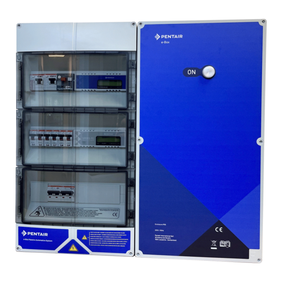
Installation and Operation Guide Version E-Box MAESTRO Lite - Description 3.3.2 The E-Box TheE-Box is a turnkey system for quickly and simply making all the connections to the various pieces of equipment in the installation. No intervention is necessary inside your E-Box except the connection to the terminal blocks, in order to carry out the connections of the various devices that constitute the installation. -
Page 19: Control Centre
Installation and Operation Guide Version E-Box MAESTRO Lite - Description 3.3.3 Control Centre The Control Centre automatically controls and calculates the operating time of the equipment connected to the system, it is the brain of the installation. It receives the orders transmitted by the remote control device or by the internet and communicates with the device concerned. -
Page 20: Probe Unit
Installation and Operation Guide Version E-Box MAESTRO Lite - Description 3.3.4 Probe Unit The device is equipped with five probes that allow it to measure the properties and values of the water. The information collected is then transmitted to the Control Centre to refine the adjustment of the water regulation. -
Page 21: Inner Display
Installation and Operation Guide Version E-Box MAESTRO Lite - Description Radio antenna Connector for Ethernet cable Power supply connector This relay, once connected to your internet box (see Internet Relay [ → Page 27]), created a radio network allowing it to send and receive information from your installation. -
Page 22: Radio Relay
Installation and Operation Guide Version E-Box MAESTRO Lite - Description 3.3.7 Radio Relay The Radio Relay is used to relay radio waves between the technical room and the internet box through the Internet Relay. It must be placed outside, for example in the garden halfway between the technical room and the house. -
Page 23: Installation
Installation and Operation Guide Version E-Box MAESTRO Lite - Installation Installation Warnings CAUTION Risk of injury due to electric shock or pressurised elements! It is strictly forbidden for any unqualified personnel to access the internal components of the system in order to carry out any technical work whatsoever. -
Page 24: Package Contents
Installation and Operation Guide Version E-Box MAESTRO Lite - Installation Package contents • 1 E-Box • 5 Cables for the connections of the MAESTRO in the E-Box • Cable glands set for installation of cables in the E-Box • 1 Control Centre MAESTRO •... -
Page 25: Accessories Provided Depending On The Options Chosen
Installation and Operation Guide Version E-Box MAESTRO Lite - Installation Accessories provided depending on the options chosen 4.3.1 Analysis chamber Supplied with the installation kit, it must be installed as close as possible to the Probe Unit box, and receives the measurement probes provided: RedOx, pH and conductivity. -
Page 26: Pool Water Treatment Liquid Solution Injection Metering Pump
Installation and Operation Guide Version E-Box MAESTRO Lite - Installation 4.3.2 Pool water treatment liquid solution injection metering pump The solution injection metering pump is supplied with the installation kit, it must be installed separately from the electrical box, integral with the wall of the technical room, in accordance with its instructions. -
Page 27: Tools Required For Installation
Installation and Operation Guide Version E-Box MAESTRO Lite - Installation Tools Required for Installation You will need the following tools in order to perform the installation in the best possible conditions: • A flat screwdriver set; • A drill with adapted bits;... -
Page 28: Inner Display
Installation and Operation Guide Version E-Box MAESTRO Lite - Installation Inner Display Caution - material Do not expose the appliance to sun (UV) or rain. Risk of irreversible damage to the interior display. The display is intended for inner use. 1. Install 4 AA batteries indoors. -
Page 29: Radio Relay
Installation and Operation Guide Version E-Box MAESTRO Lite - Installation Radio Relay Start-up Info Switching on a Radio Relay or Inner Display triggers the recognition/machine learning of a radio code. 1. Remove the the tub by pulling on the tab. - Page 30 Installation and Operation Guide Version E-Box MAESTRO Lite - Installation Positioning Info The Radio Relay should be placed high up (on a wall or pole for example), away from any metal object (iron fence, zinc gutter). 1. Use the compass to orient the Radio Relay to the south thanks to the reference provided for this purpose.
-
Page 31: E-Box
Installation and Operation Guide Version E-Box MAESTRO Lite - Installation E-Box 4.8.1 Wall mounting Caution - material The device must not be installed outdoors, preferring instead a technical room inaccessible to children. • Ensure that the bracket on which the appliance is installed can support a load of 10 kg. -
Page 32: Connections
Installation and Operation Guide Version E-Box MAESTRO Lite - Installation Info The quick-connect cables are connected to the bottom of theE-Box (7). Install the cable ducts provided according to the diameter and number of cables used. The cable ducts prevent moisture or acid vapour from entering the device. Never leave an empty hole unused without protection. - Page 33 Installation and Operation Guide Version E-Box MAESTRO Lite - Installation 230V socket MAESTRO Power supply connector MAESTRO Control connector MAESTRO Data connector MAESTRO Information connector Cable routing Main protection with 30 mA differentials Single speed pump thermal protection Pool Light Transformer 12V/300VA...
- Page 34 Installation and Operation Guide Version E-Box MAESTRO Lite - Installation 1. High voltage connection (230V) 2. Low voltage connection (12/24V) Terminal block 1: High voltage Terminal block 2: Low voltage connection (230V) [ → Page 34] connection (12-24 V) [ →...
-
Page 35: Connecting The "Single Speed" Filter Pump
Installation and Operation Guide Version E-Box MAESTRO Lite - Installation Connection of the heat pump power supply (230V 20A) Variable Speed Pump Supply Connection (230V 15A) Connecting the Pool Automatic Shutter Power Supply (230V 16A) 9-10 Connecting the Single Speed Filter Pump Power Supply (230V 4 – 6.3A) -
Page 36: Connection Of The Heat Pump Power Supply (If Installed)
Installation and Operation Guide Version E-Box MAESTRO Lite - Installation Position of the thermal protection of the single speed filtration pump, with adjustment of the protection amperage Mandatory Do not forget to adjust the thermal protection to the protection rating of the filtration pump used. -
Page 37: Connection Of The Pool Automatic Shutter Power Supply (If Equipped)
Installation and Operation Guide Version E-Box MAESTRO Lite - Installation Control of the electrolyser through the dry contacts 15 and 16. 4.8.6 Connection of the pool automatic shutter power supply (if equipped) The connection of the supply phase, the neutral and the earth must be made through the connection terminal block according to terminals 7 and 8 (for the earth connection: proceed to the connection on the dedicated terminal block). - Page 38 Installation and Operation Guide Version E-Box MAESTRO Lite - Installation 4. Install the upper screw (1) and hang the device (2) in the place provided for this purpose. 5. Secure the appliance (2) using the two bottom screws (4). 6. Install the two covers (3) of the screws in order to ensure the tightness of the device (2).
-
Page 39: Hydraulic And Electrical Installation
Installation and Operation Guide Version E-Box MAESTRO Lite - Installation 4.9.2 Hydraulic and electrical installation The diagram below illustrates the electrical and hydraulic connections of the Probe Unit with the analysis chamber. Mandatory It is imperative to isolate the bypass by closing both valves before changing a probe. -
Page 40: Installation Of Probes
Installation and Operation Guide Version E-Box MAESTRO Lite - Installation Install the probes in the analysis chamber The Probe Unit comes with a probe to having previously removed the lower part measure water temperature. A second (the transparent bowl) of the analysis probe (optional) can be installed to chamber. - Page 41 Installation and Operation Guide Version E-Box MAESTRO Lite - Installation 1. Unscrew the spigots. Screw/unscrew cylinders Never push or pull the cylinders that have the cap Prohibition Prohibition of pushing or pulling the cramps. Risk of damage to probes. 2. Install the probes in the analysis chamber provided.
- Page 42 Installation and Operation Guide Version E-Box MAESTRO Lite - Installation Installing the water temperature sensor Install the water temperature probe preferably before the pump filtration system. 1. Drill the PVC pipe (Ø50-70 mm) to make a hole with a diameter of 10 mm.
-
Page 43: Connections
Installation and Operation Guide Version E-Box MAESTRO Lite - Installation 4.9.4 Connections 4.9.4.1 Probe Units Connections Quick connection to the Control Centre Cable feed for probes Swimming pool shutter limit switch Liquid Chlorine Pump Low Level Sensor pH Regulator Pump Low Level Sensor... - Page 44 Installation and Operation Guide Version E-Box MAESTRO Lite - Installation 4.9.4.2 Control Centre connections Connector cable 1 connected with the E-Box Link and information cable with the Probe Unit Information contact cable Connection with the E-Box Connector cable for control link with the E-Box...
- Page 45 Installation and Operation Guide Version E-Box MAESTRO Lite - Installation Info Only the Pentair probes are compatible and guarantee the proper functioning of the device. Normally open level sensor (switch closed = tank empty) Connection of a roller shutter limit switch 1.
- Page 46 Installation and Operation Guide Version E-Box MAESTRO Lite - Installation Connection of secondary lighting (garden, atmosphere) with a power of less than 1600 W. Info The main pool lighting must be connected directly to the E-Box. 1. Connect the lighting according to the diagram below.
- Page 47 Installation and Operation Guide Version E-Box MAESTRO Lite - Installation > 20A through terminal blocks 25-26 Ref. SB-CU-IMP-062EBLA / A - 11.05.2023 47 / 90...
-
Page 48: Programming
Installation and Operation Guide Version E-Box MAESTRO Lite - Programming Programming Programming the MAESTRO Control Centre 5.1.1 Presentation Time Settings menu Setting menu [ Page 49] → Date Lighting menu Lighting menu [ Page 52] → Water temperature Filtration menu Filtration menu [ Page 52]... -
Page 49: Setting Menu
Installation and Operation Guide Version E-Box MAESTRO Lite - Programming 5.1.1.1 Navigation keys Exhaust Go back to the previous step without considering the changes. Displacement down/decrementation Navigation down in drop-down menus or decrementation of values in numerical spaces. Displacement up/incrementation Upward navigation in drop-down menus or incrementing values in numerical spaces. - Page 50 Installation and Operation Guide Version E-Box MAESTRO Lite - Programming Disinfectant Options: • Auto: Automatically adjust based on RedOX. • Off: Turn off the power to the electrolyser completely. • Instruction: Change the RedOx value to be reached in Auto mode (650 mV factory).
- Page 51 Installation and Operation Guide Version E-Box MAESTRO Lite - Programming 1. Select the radio menu option with 2. Press to confirm the selection and proceed to the next parameter. Memo. Installation The menu asks to start learning on the immersed case.
-
Page 52: Lighting Menu
Installation and Operation Guide Version E-Box MAESTRO Lite - Programming 5.1.3 Lighting menu Options: • Manual: Have access to lighting through the remote control. • Clock: Set the time slots in the Clock Setting sub-menu. • Off: Permanently turn off the lighting. -
Page 53: Aux1 Menu
Installation and Operation Guide Version E-Box MAESTRO Lite - Programming Filtration Settings • This setting increases or decreases the filtration time to compensate for pump size and/or activity in the pool • Factory settings (editable in the Installation menu): – Turbo = +30% –... -
Page 54: History Menu
Installation and Operation Guide Version E-Box MAESTRO Lite - Programming 5.1.6 History Menu 1. Access the secure menu history of the day MAESTRO by pressing for 4 secs. 2. Access the 4 pages of the history of the day by pressing on :... - Page 55 Installation and Operation Guide Version E-Box MAESTRO Lite - Programming • Eco (default -30%): Decreases the filtration time (in %) from the normally calculated time. • Turbo (default +30%): Increases the filtration time (in %) of the normally calculated time.
-
Page 56: Inner Display Programming
Installation and Operation Guide Version E-Box MAESTRO Lite - Programming Inner Display Programming 5.2.1 Presentation The remote Inner Display informs of all parameters (updated every 15 minutes) of water quality and comfort (temperatures, UV). Intended for inner use, pre-programmed alerts make it possible at a glance to check the chemical balance of the water without making the tedious analyses at the edge of the basin. -
Page 57: Air/Water Temperature
Installation and Operation Guide Version E-Box MAESTRO Lite - Programming Audible Alarm Status Radio Signal Strength On/off Radio Signal Strength [ Page 71] → Audible Alarm Status [ Page 70] → 5.2.1.1 Navigation keys Info Pressing any key stops an audible alarm. - Page 58 Installation and Operation Guide Version E-Box MAESTRO Lite - Programming 5.2.2.1 Temperatures The Inner Display provides the temperature in °C): The air temperature accompanied by the pictogram e.g.: The air temperature is 28.5°C The water temperature accompanied by the pictogram e.g.: The water temperature is 24.0°C...
-
Page 59: Ph Trend
Installation and Operation Guide Version E-Box MAESTRO Lite - Programming The gel pictogram related to the air temperature is displayed if the temperature measured by the Radio Relay is less than +3°C. The water temperature is 0.5°C 5.2.2.3 UV level (not guaranteed, for information only) The UV level is provided as an indication for sensitization to the skin risks of exposure to the sun between 11am and 3pm. - Page 60 Installation and Operation Guide Version E-Box MAESTRO Lite - Programming The pH has reached alarm • the pH has reached the maximum alarm value value (factory pre-set at 6.7 can be modified through the alarm menu, see Alarm mode [ →...
-
Page 61: Conductivity Trend
Installation and Operation Guide Version E-Box MAESTRO Lite - Programming CAUTION pH too high or too low! Skin irritation ü Ensure that: ü the cylinder has been removed from the pH probe (see Installation of probes → Page 40]) ü the pH probe was calibrated less than 6 months ago (see Calibration mode →... - Page 62 Installation and Operation Guide Version E-Box MAESTRO Lite - Programming Unit used • g/l unit used for salt electrolysis • µS unit used without salt electrolysis The choice of the conductivity unit (μS or g/l) is made by the mode calibration/change of units (see Calibration mode →...
-
Page 63: Redox Trend
Installation and Operation Guide Version E-Box MAESTRO Lite - Programming 5.2.5 RedOx Trend RedOx Trend (Updated • the RedOx every 2h) • redOx is stable • the RedOx decreases RedOx has reached alarm • the RedOx has reached the maximum alarm value value (factory pre-set at 800 ... -
Page 64: Mode In Progress
Installation and Operation Guide Version E-Box MAESTRO Lite - Programming CAUTION A RedOx too high can damage elements of the basin! A RedOx too low can be dangerous for hygiene! ü ensure that: ü the spigot has been removed from the RedOx probe (see Probe Unit [ →... - Page 65 Installation and Operation Guide Version E-Box MAESTRO Lite - Programming 1. Place the switch in alarm mode (rear side of the Inner Display). calib alarm ð Alarm mode is selected on the Inner Display: 2. Press to select the pH low alarm.
- Page 66 Installation and Operation Guide Version E-Box MAESTRO Lite - Programming 12. Use to set the conductivity low alarm value 13. Press to validate the conductivity low alarm value. 14. Press to select the conductivity high alarm. 15. Press to select the conductivity value 16.
- Page 67 Installation and Operation Guide Version E-Box MAESTRO Lite - Programming Change of units & voluntary correction of values Info All these values remain stored when changing batteries. This mode allows you to modify the units of: • air temperature & water temperature (factory pre-set in °C);...
- Page 68 4. Return the switch to the ON mode (rear side of the Inner Display). Calibration of a pH probe Due to its nature, a pH probe needs to be recalibrated regularly (preferably before the season). The pH Probe Pentair is available as a spare part from your dealer Pentair. Tools • pH probe;...
- Page 69 Installation and Operation Guide Version E-Box MAESTRO Lite - Programming 1. Place the switch in calibration mode (rear side of the Inner Display). calib alarm ð Calibration mode is selected on the Inner Display: 2. Press 5 times to select the pH trend.
-
Page 70: Audible Alarm Status
Installation and Operation Guide Version E-Box MAESTRO Lite - Programming ð The procedure is complete. ð Procedure ð Check the presence of a pH 4.0 solution in contact with the probe for the duration of the procedure. ð The probe is no longer functional (to be replaced). -
Page 71: Battery Level
Installation and Operation Guide Version E-Box MAESTRO Lite - Programming 5.2.9 Battery level The level of the batteries is displayed under the pictogram representing each element concerned. Battery life is longer than 1 year but may vary depending on weather and usage conditions. -
Page 72: Operations
Installation and Operation Guide Version E-Box MAESTRO Lite - Operations Operations Commissioning Turning on When first starting up: • the facade panels must be installed on the E-Box; • the light on the front of the E-Box box must be illuminated, indicating the presence of voltage;... - Page 73 Installation and Operation Guide Version E-Box MAESTRO Lite - Operations Info Switching on a Radio Relay or Inner Display triggers the recognition/machine learning of a radio code. New Radio Relay no. 2 1. Remove the the tub by pulling on the tab.
-
Page 74: Re-Learning The Original Inner Display
Installation and Operation Guide Version E-Box MAESTRO Lite - Operations New display no. 2 1. Remove the battery door. 2. Remove the insulating film from the batteries. 3. Inner Display no. 2 goes into radio learning mode. 4. Inner Display no. 2 displays the same values as Inner Display no. 1. -
Page 75: Operation Of The Internet Relay
Installation and Operation Guide Version E-Box MAESTRO Lite - Operations ð The Inner Display goes into radio learning mode. 4. The Inner Display displays the values. 5. Replace the battery door. 6. Replace the orange cover on the MAESTRO Probe Unit. -
Page 76: Home Automation-Pool Account
Installation and Operation Guide Version E-Box MAESTRO Lite - Operations Grid connection led Initialization fault or no power supply ( Check the connection of the power cable. Lack of network ( Check the connection of the Ethernet cable and check the internet connection. - Page 77 Installation and Operation Guide Version E-Box MAESTRO Lite - Operations The serial number is located on the identification plate of the Inner Display, it is the five digits that follow the letters SN (1). This number can also be found on the last cover page of this document.
-
Page 78: Maintenance
Installation and Operation Guide Version E-Box MAESTRO Lite - Maintenance Maintenance Maintenance Clean the outside of the various items with a dry microfiber cloth. Do not use solvents, abrasives or acids. Wintering of the MAESTRO (T° water < +3.0°C) • Over-wintering: the forced operation of the pump prevents the formation of ice on the surface. -
Page 79: Radio Relay And Inner Display
Installation and Operation Guide Version E-Box MAESTRO Lite - Maintenance Radio Relay and Inner Display Radio Relay The Radio Relay being fixed to the outside, the appearance of traces of deposition is quite normal. 1. Clear and clean the lens of any bodies obstructing the window (sheets, stains, etc.) Inner Display The Inner Display is exclusively intended for inner use. - Page 80 Installation and Operation Guide Version E-Box MAESTRO Lite - Maintenance 3. Rinse the tip of the probe thoroughly under running water for 5 minutes. 5 min 4. Screw the protective cage back on gently. 5. For pH probe only, calibrate the probe.
-
Page 81: Alkaline Battery Replacement
Installation and Operation Guide Version E-Box MAESTRO Lite - Maintenance Alkaline battery replacement The life of the batteries supplied is more than one year (depending on the conditions of use). New batteries must be alkaline type, do not use rechargeable batteries. -
Page 82: Changing Inner Display Batteries
Installation and Operation Guide Version E-Box MAESTRO Lite - Maintenance 4. Reconnect the battery pack. 5. Red LED flashes for 10 s. ð The Inner Display Radio Relay battery symbol shall indicate full batteries after 30 s. 6. Raise the jar. 7.6.2 Changing Inner Display Batteries ü... - Page 83 Installation and Operation Guide Version E-Box MAESTRO Lite - Maintenance 4. Check the battery power level on the Inner Display screen. 5. Replace the protective cover (2). ð Battery level is updating. Info Changing the batteries does not erase the customisation of the Inner Display programming.
-
Page 84: Troubleshooting
Installation and Operation Guide Version E-Box MAESTRO Lite - Troubleshooting Troubleshooting Alert Messages Alert Messages Meanings MAESTRO does not manage to stop or launch the filtration. 1. Check the connections, that the 3-position switch is on Clock/Auto and the correct connection of A1A2. -
Page 85: Spare Part
Installation and Operation Guide Version E-Box MAESTRO Lite - Spare part Spare part Genuine parts, necessary for the maintenance of your device Pentair, are available at your dealers. SB Item Code Description Diagram SB-PD-PRO-001A pH probe 50 cm cable and standard solutions pH4 &... -
Page 86: Disposal
This will help reduce the impact on the environment, health and safety, and also promote recycling. Pentair does not collect used products for recycling. Contact your local recycling centre. for more information. -
Page 87: Annexes
Installation and Operation Guide Version E-Box MAESTRO Lite - Annexes Annexes Electrical diagrams of the Maestro Ref. SB-CU-IMP-062EBLA / A - 11.05.2023 87 / 90... - Page 88 Installation and Operation Guide Version E-Box MAESTRO Lite - Annexes 88 / 90 Ref. SB-CU-IMP-062EBLA / A - 11.05.2023...
- Page 89 Installation and Operation Guide Version E-Box MAESTRO Lite - Annexes Ref. SB-CU-IMP-062EBLA / A - 11.05.2023 89 / 90...
- Page 90 WWW.PENTAIRPOOLEUROPE.COM All Pentair trademarks and logos are the property of Pentair. The brands, trademarks and logos of third parties are the property of their respective owners. © 2023 Pentair. All rights reserved.
Need help?
Do you have a question about the E-Box MAESTRO Lite and is the answer not in the manual?
Questions and answers