Pentair Fleck 2510 Service Manual
Hide thumbs
Also See for Fleck 2510:
- Service manual (40 pages) ,
- Service manual (20 pages) ,
- Service manual (28 pages)

Related Manuals for Pentair Fleck 2510


Summary of Contents for Pentair Fleck 2510
- Page 1 ientsw MODEL 2510 & 2510 ECONOMINDER Service Manual IMPORTANT: Fill in pertinent information on page 2 for future reference.
-
Page 2: Job Specification Sheet
main MODEL 2510 & 2510 ECONOMINDER head job specification sheet • JOB NO. _________________________________________________________ • *MODEL NO. ______________________________________________________ • WATER TEST _____________________________________________________ • CAPACITY PER UNIT ____________ MAX. __________ PER REGENERATION • MINERAL TANK SIZE DIA. _______ HEIGHT _________ • BRINE TANK SIZE & SALT SETTING PER REGENERATION: _________________________________________________________________ •... -
Page 3: Installation Instructions
main MODEL 2510 & 2510 ECONOMINDER head sub- installation instructions head WATER PRESSURE: A minimum of 20 pounds of water pressure is required for regeneration valve to operate effectively. ELECTRICAL FACILITIES: An uninterrupted alternating current (A/C) supply is required. Note: Other voltages are available. -
Page 4: Start-Up Instructions
main MODEL 2510 & 2510 ECONOMINDER head ® sub- start-up instructions head The water softener should be installed with the inlet, outlet and drain connections made in accordance with the manufacturer’s recommendations and to meet applicable plumbing codes. 1. Remove control box cover. 2. -
Page 5: Timer Setting Procedure
model MODEL 3200 TIMER 3210 remote meter timer setting procedure timer Delayed Regen- eration How To Set Days On Which Water SERVICE Timer Conditioner Is To Regenerate: POSITION 24 HR. GEAR INDICATOR Assem- MANUAL REGENERATION KNOB Rotate the skipper wheel until the number “1” is at the red pointer. - Page 6 MODEL 3200 TIMER regeneration cycle program setting procedure (brine tank refill separate from rapid rinse - stf) Black drive cam and brine valve cam How To Set Regeneration Cycle Program: BRINE & RINSE PROGRAM SECTION The regeneration cycle program on your water WHEEL FOR (2 MIN.
- Page 7 MODEL 3200 TIMER regeneration cycle program setting procedure (rapid rinse) White drive cam and brine valve cam How To Set The Regeneration Cycle Program: PROGRAM BRINE & RINSE WHEEL FOR SECTION The regeneration cycle program on your water CONTROL OF (2 MIN.
- Page 8 MODEL 3200 TIMER timer assembly (see opposite page for parts list) Page 8...
- Page 9 MODEL 3200 TIMER timer assembly (parts list) Item No. No. Req’d Part No. Description 1 ... 1 ... 13870 ....Timer Housing 2 .
-
Page 10: Control Valve Drive Assembly
MODEL 2510 control valve drive assembly (see opposite page for parts list) Page 10... - Page 11 MODEL 2510 control valve drive assembly (parts list) Item No. No. Req’d Part No. Description 1 ... 1 ... 14884 ....Back Plate - Stainless Steel 2 .
-
Page 12: Control Valve Assembly
MODEL 2510 control valve assembly (see opposite page for parts list) OPTIONAL BACKWASH PARTS Page 12... - Page 13 MODEL 2510 control valve assembly (parts list) Item No. No. Req’d Part No. Description 1 ... 1 ... 19328 ....Valve Body 2 .
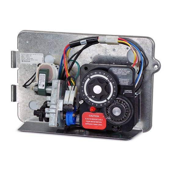
- Page 14 MODEL 2510 ECONOMINDER demand regeneration control Typical Residential Application SERVICE To program, just set the time, set the hardness and it POSITION MANUAL REGENERATION INDICATOR 24 HR. GEAR KNOB automatically monitors system needs and regenerates only when necessary. To set time of day press red time set button and turn 24 hour gear until present time of day is opposite “time of day arrow.”...
- Page 15 MODEL 3210 regeneration cycle program setting procedure How to Set The Regeneration Cycle Program: PROGRAM BRINE & RINSE WHEEL FOR SECTION The regeneration cycle program on your water conditioner CONTROL OF (2 MIN. PER HOLE) has been factory preset, however, portions of the cycle or REGENERATION CYCLE program may be lengthened or shortened in time to suit...
-
Page 16: Timer Assembly
MODEL 3210 timer assembly (see opposite page for parts list) Page 16... - Page 17 MODEL 3210 timer assembly (parts list) Item No. No. Req’d Part No. Description 1 ... 1 ... 13870-01 ... . . Timer Housing Assembly 2 .
- Page 18 MODEL 2510 ECONOMINDER control valve drive assembly (see opposite page for parts list) Page 18...
- Page 19 MODEL 2510 ECONOMINDER control valve drive assembly (parts list) Item No. No. Req’d Part No. Description 1 ... 1 ... 14884 ....Back Plate - Stainless Steel 2 .
- Page 20 MODEL 2510 ECONOMINDER meter assembly (see opposite page for parts list) Page 20...
-
Page 21: Meter Assembly
MODEL 2510 ECONOMINDER meter assembly (parts list) Item No. No. Req’d Part No. Description 1 ... 4 ... 12473 ....Screw - Meter Cover Assembly 2 . - Page 22 MODEL 1650 plastic brine system for 2510 and 2510 econominder (see opposite page for parts list) Page 22...
- Page 23 MODEL 1650 plastic brine system for 2510 and 2510 econominder (parts list) Item No. No. Req’d Part No. Description 60011 Brine Valve Assembly, Includes Items 3-15 (Less BLFC 60010-) 1 ... 1 ... 10328 ....Elbow, 90 1/4 NPT x 3/8 2 .
-
Page 24: Parts List
MODEL 2510 coupling assembly with yoke PARTS LIST Item No. No. Req’d Part No. Description 1... . 4... . 13305....O-Ring, Adapter Coupling 2. -
Page 25: Service Assemblies
MODEL 2510 service assemblies (parts list) 60090 ....Piston Assembly (For Illustration and Parts, See Page 12) 60050-21 ....2510/2750 Drive Motor Assembly - STF (For Illustration and Parts, See Pages 10 &... - Page 26 MODEL 2510 & 2510 ECONOMINDER wiring diagram for valve drive motor and timer 2510 downflow Tank Dia. Resin Load Injector Inj. Color Draw / Slow Rinse Rate (GPM)* BLFC** DLFC*** Timer Settings**** Total Capacity 6” .35 Cu Ft #000 Brown .11 gpm / .19 gpm .25 gpm .8 gpm...
- Page 27 MODEL 2510 & 2510 ECONOMINDER service instructions PROBLEM CAUSE CORRECTION Softener Fails to Regenerate Electrical Service To Unit Has Been Assure Permanent electrical Service Interrupted. (Check Fuse, Plug, Pull chain or Switch). Timer is Defective Replace Timer. C. Power Failure. C.
-
Page 28: General Service Hints For Meter Control
MODEL 2510 & 2510 ECONOMINDER service instructions (continued) PROBLEM CAUSE CORRECTION Excessive Water in Brine Tank C. Timer Not Cycling. C. Replace timer. (continued) Foreign Material in Brine Valve. Replace Brine Valve Seat and Clean Valve. Foreign Material in Brine Line Flow Clean Brine Line Flow Control. - Page 29 MODEL 2510 & 2510 ECONOMINDER tools used in seal and spacer replacement NUT DRIVER ADAPTER SOCKET SEAL HOOK PULLER STUFFER Tools Used in the Seal and Spacer Replacement Nut Driver #12664 Socket Adapter #16906 Socket 7/16” #12665 Seal Hook #12874 Puller #13061 Stuffer...
- Page 30 MODEL 2510 & 2510 ECONOMINDER seal and spacer replacment 1. Turn off water supply to valve. Next, cycle valve to backwash position, then to service. Now remove BACK PLATE electrical plug from outlet. LINE TO INJECTOR BRINE 2. Remove control box cover. VALVE 3.
- Page 31 MODEL 2510 & 2510 ECONOMINDER seal and spacer replacement (continued) 9. Alternately remove the remaining seals and spacers in accordance with steps No. 6 and 8. INJECTOR SPACER 10. The last or end spacer odes not have any holes for the BRINE pins of the spacer tool to engage, therefore if the end PULLER...
- Page 32 MODEL 2500 ECONOMINDER seal and spacer replacement (continued) 15. While the tool is still in the valve, press another seal into the inside diameter of the exposed brass sleeve end. 16. Remove the stuffer, turn it end for end, and insert it into the valve body bore.
- Page 33 MODEL 2510 & 2510 ECONOMINDER Notes Page 33...
- Page 34 MODEL 2510 & 2510 ECONOMINDER Notes Page 34...
- Page 36 P / N 40097 Rev. 2 5/98 Printed 7/99...
Need help?
Do you have a question about the Fleck 2510 and is the answer not in the manual?
Questions and answers