
Related Manuals for Progetti Rescue Life 9


Summary of Contents for Progetti Rescue Life 9
- Page 1 INSTRUCTION FOR USE Defibrillator Rescue Life PROGETTI S.r.l. Rev. 0.5 Strada del Rondello, 5 30/03/2022 10028 Trofarello (TO) Rev. 0.0 ITALY...
- Page 2 Rescue Life – Instruction For Use Rev.0.5 – 30/03/2022...
-
Page 3: Table Of Contents
Rescue Life – Instruction For Use Rev.0.5 – 30/03/2022 Summary 1 INTRODUCTION ........................1 INTENDED USE (patients group and medical conditions) ............2 1.2 MEDICAL DEVICE DESCRIPTION ...................... 4 1.2.1 MAIN UNIT ................................. 5 1.2.2 ACCESSORIES VIEW ............................15 1.2.3 LABELLING VIEW .............................. 19 1.3 INDICATIONS .......................... - Page 4 Rescue Life – Instruction For Use Rev.0.5 – 30/03/2022 3 ACQUISITION OF BIOMEDICAL PARAMETERS ................1 3.1 ECG ACQUSITION ......................2 3.1.1 ECG PATIENT CABLE CONNECTION AND ELECTRODES PLACEMENT ..........2 3.1.2 PROCEDURE ..........................2 3.1.3. ECG ALARMS SETTING ....................... 8 3.1.4 ECG PERFORMANCE (REF.
- Page 5 4.6.2 LOAD SETUP ..........................18 4.6.2.1 PROCEDURE ..............................18 4.6.3 DEFAULT SETUP ........................19 4.6.3.1 PROCEDURE ..............................19 RESCUE LIFE 9 CHECKLIST ......................1 APPENDIX A ..........................1 CLINICAL INFORMATION ........................1 How does biphasic waveform defibrillate?................... 1 Ease in compensation of patient impedance ..................2 More efficient than monophasic waveform ..................
- Page 6 Rescue Life – Instruction For Use Rev.0.5 – 30/03/2022 IMPORTANT ............................1 DESCRIPTION ............................1 PACKAGING ............................1 INDICATIONS ............................1 CONTRAINDICATIONS ......................... 1 MODE OF USE ............................. 1 MODE OF APPLICATION ........................2 POSITIONING AND POLARITY ......................3 SIDE EFFECTS ............................3 PRECAUTIONS AND WARNINGS ......................
- Page 7 +39.011.644.738 The information contained in this document may be subject to change without notice. Limited Warranty The "Limited Warranty" shipped with PROGETTI products is the one and only with regard to the product. Useful contacts •...
-
Page 8: Introduction
INTRODUCTION... -
Page 9: Intended Use (Patients Group And Medical Conditions)
The pacing option is indicated for treating patients with symptomatic bradycardia. Used in AUTOMATED MODE (AED), RESCUE LIFE 9 is designed to be used on adult patients (by use of DISPOSABLE MULTINFUNCTIONAL ELECTRODES – ADULT PATIENTS), on pediatric patients (by use of DISPOSABLE MULTINFUNCTIONAL ELECTRODES –... - Page 10 Rev.0.5 – 30/03/2022 1 - INTRODUCTION When used in AED mode, the RESCUE LIFE 9 is a semiautomatic defibrillator that provides a prompted treatment protocol and ECG analysis using special analysis algorithm. This software algorithm analyzes the patient’s electrocardiographic (ECG) rhythm and indicates whether or not a shockable rhythm is detected.
-
Page 11: Medical Device Description
1 - INTRODUCTION 1.2 MEDICAL DEVICE DESCRIPTION RESCUE LIFE 9 is an external defibrillator and monitor for acute cardiac care response used by authorized healthcare providers in hospital and clinic settings. The RESCUE LIFE 9 is available only with the biphasic defibrillation waveform. The delivered energy is adjusted to the patient impedance to obtain the best result. -
Page 12: Main Unit
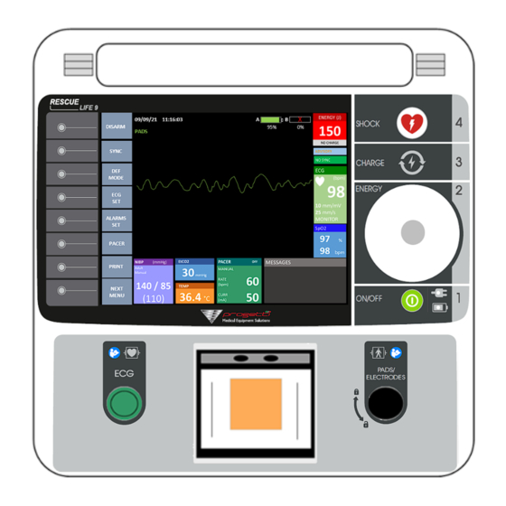
Rescue Life – Instruction For Use Rev.0.5 – 30/03/2022 1 - INTRODUCTION 1.2.1 MAIN UNIT FRONT VIEW REAR VIEW LEFT VIEW (full optional case) - Page 13 Rescue Life – Instruction For Use Rev.0.5 – 30/03/2022 1 - INTRODUCTION 1.2.1.1 FRONT PARTS PART IDENTIFICATION ICON PURPOSE ON/OFF BUTTON To power ON/OFF KNOB N.A. To select a field displayed or to increase/decrease defibrillation energy CHARGE BUTTON To enable the charging of defibrillation energy SHOCK BUTTON To deliver the shock when the red light is ON and the disposable multifunction electrodes are used...
- Page 14 Rescue Life – Instruction For Use Rev.0.5 – 30/03/2022 1 - INTRODUCTION 1.2.1.2 GRAPHIC INTERFACE 13.14 13.13 13.12 13.11 13.10 13.9 13.8 13.7 13.6 13.3 13.4 13.2 13.5 13.1 7.17 7.18 7.10 7.19 7 11 7.12 7.20 7.21 7.13 7.14 7.15 7.22 7.16...
- Page 15 Rescue Life – Instruction For Use Rev.0.5 – 30/03/2022 1 - INTRODUCTION IDENTIFICATION PURPOSE to perform INTERNAL DISCHARGE DISARM to enable/disable SYNC MODE. SYNC to open DEFIBRILLATION MODES window (“Manual”, “AED”, “Advisory” mode are available). MODE to set ECG PARAMETERS The following items are available: PADS: •...
- Page 16 Rescue Life – Instruction For Use Rev.0.5 – 30/03/2022 1 - INTRODUCTION to set ALARMS PARAMETERS. The following items are available: • ECG HR alarm: set the maximum and minimum ALARMS heart rate alarm; • alarm: set the SpO minimum alarm; •...
- Page 17 Rescue Life – Instruction For Use Rev.0.5 – 30/03/2022 1 - INTRODUCTION to open NIBP FUNCTIONS (violet “NIBP MODE” is 7.11 shown on the top of display): • (7.11.1) START MEAS – to start measurement; • (7.11.2) STOP MEAS – to stop measurement; •...
- Page 18 Rescue Life – Instruction For Use Rev.0.5 – 30/03/2022 1 - INTRODUCTION to SAVE the parameters settings: 7.17 • ECG SPEED • ECG GAIN • ECG FILTER • ALARM HR MIN • SAVE ALAR HR MAX • ALARM SPO2 MIN SETUP •...
- Page 19 Rescue Life – Instruction For Use Rev.0.5 – 30/03/2022 1 - INTRODUCTION 13.1 NIBP field (if available) to show NIBP SETUP AND MEASUREMENT The following values are possible: • NIBP ALARM enabled /disabled • ADULT / PEDIATRIC • MANUAL / ON DEMAND •...
- Page 20 Rescue Life – Instruction For Use Rev.0.5 – 30/03/2022 1 - INTRODUCTION 13.10 DEF MODE field to show the actual SET DEFIBRILLATION MODE (manual, AED, ADV) 13.11 CHARGE status show ENERGY CHARGING STATUS (CHARGING / NO CHARGE) 13.12 ENERGY field To show SELECTED ENERGY VALUE [J] 13.13 BATTERY field To show BATTERIES CHARGE STATUS [%]...
- Page 21 Rescue Life – Instruction For Use Rev.0.5 – 30/03/2022 1 - INTRODUCTION 1.2.1.4 LEFT PANEL CONNECTIONS (full optional version) PART IDENTIFICATION PURPOSE PORT (if available) sensor connection EtCO PORT (if available) EtCO sensor connection TEMPERATURE PORT (if available) TEMPERATURE connection NIBP PORT (if available) NIBP extension cable connection USB PORT (if available)
-
Page 22: Accessories View
Rescue Life – Instruction For Use Rev.0.5 – 30/03/2022 1 - INTRODUCTION 1.2.2 ACCESSORIES VIEW 1.2.2.1 Standard Accessories Standard Defibrillation Electrodes (qty:1) Disposable Multifunction Electrodes for Defibrillator - REF: RLF9-STDEFEL adult patient (qty:1) REF: DFBAD01STD Extension cable for disposable electrodes (qty:1) ECG cable - 5 wires (qty:1) REF: RLF9-DISPEXCAB REF: A5022-EC0... - Page 23 Rescue Life – Instruction For Use Rev.0.5 – 30/03/2022 1 - INTRODUCTION 1.2.2.2 Optional Accessories ECG cable - 10 wires sensor - adult patient REF: A1022-EE0 REF: S136AL sensor (for pediatric patient) REF: S136CL ECG cable – 3 wires REF: A3022-EC0 wrap sensor REF: S136EL 1-16...
- Page 24 Rescue Life – Instruction For Use Rev.0.5 – 30/03/2022 1 - INTRODUCTION EtCO kit sensor NIBP cuff (Adult Version - small) REF: TG-981T REF: 98-0095-04 NIBP cuff (Adult Version - standard) REF: 98-0097-04 NIBP cuff (Pediatric Version) REF: 98-0093-03 NIBP cuff (Infant Version) REF: 98-0092-02 1-17...
- Page 25 Rescue Life – Instruction For Use Rev.0.5 – 30/03/2022 1 - INTRODUCTION NIBP extension cable Skin Temperature sensor (YSI400 Compatible) REF: 91-0028-69 REF: ATP-03 Disposable Multifunction Electrodes for Defibrillator (pediatric version) REF: RLF9-BAG REF: DFB01PEDPRC 1-18...
-
Page 26: Labelling View
– Instruction For Use Rev.0.5 – 30/03/2022 1 - INTRODUCTION 1.2.3 LABELLING VIEW The symbols are present in the below rear sticker or in the package of Rescue Life 9 defibrillator. SYMBOL DESCRIPTION OF SYMBOL Identification of device Serial Number of device... - Page 27 Rescue Life – Instruction For Use Rev.0.5 – 30/03/2022 1 - INTRODUCTION Caution: dangerous voltage (ref. IEC 60878) Signal of general warning (ref. ISO 7010-W001) The user must to consult the instructions for use for important cautionary information such as warnings and precautions that cannot, for a variety of reasons, be presented on the medical device itself.
-
Page 28: Indications
ADVISORY or AED mode. This Operator’s Manual contains all the information that a user needs to operate the RESCUE LIFE 9 properly. PROGETTI S.r.l. reserves the right to make changes on the device specifications contained in this manual at any time without prior notice or obligation to customer. - Page 29 It is very important that you fully understand all the necessary instructions discussed in this manual so as to act quickly in an emergency. PROGETTI S.r.l. designs and manufactures all of its products in compliance to Directives 2007/47/EC and 93/42/EEC concerning Medical Devices.
-
Page 30: Danger, Warnings And Cautions
1.5.3 GENERAL Assure yourself prior and after the use of the RESCUE LIFE 9 that the unit is in safe and usable condition (cables integrity, pads, battery status). - Page 31 3. Disconnect other electrical equipment from the patient before defibrillating. 4. Improper use can cause injury. Use the rescue life 9only as instructed in the user manual. The rescue life 9 delivers electrical DEFIBRILLATION energy that can potentially cause death or injury if it is used or discharged improperly.
- Page 32 2. Portable rf communications equipment (including peripherals such as antenna cables and external antennas) should be used no closer than 30 cm (12 inches) to any part of the rescue life 9, including cables specified by the manufacturer. Otherwise, degradation of the performance of this equipment could result.
- Page 33 Rescue Life – Instruction For Use Rev.0.5 – 30/03/2022 1 - INTRODUCTION 1. Aggressive or prolonged CPR to a patient with disposable self- adhesive defibrillation/monitoring electrodes (pads) attached can cause damage to the pads. Replace the defibrillation pads if they become damaged during use.
- Page 34 Rescue Life – Instruction For Use Rev.0.5 – 30/03/2022 1 - INTRODUCTION 1. Do not clean with ketones or other flammable agents. CLEANING 2. Do not autoclave or sterilize this defibrillator or accessories unless otherwise specified. CAUTION Avoid contact between parts of the patient’s body and conductive DEFIBRILLATION fluids such as water, gel, blood or saline, and metal objects, which may provide unwanted pathways for shock current.
- Page 35 Rescue Life – Instruction For Use Rev.0.5 – 30/03/2022 1 - INTRODUCTION 1. Do not disassemble the defibrillator or its accessories. It contains no user serviceable parts. High voltage may be present. Contact authorized service personnel for professional maintenance. MAINTENANCE 2.
-
Page 36: Possible Improper Device Performance
RAY EQUIPMENT RADIO TRANSMITTERS CELLULAR MOBILE TELEPHONES AND OTHERS AS THESE MIGHT INTERFERE WITH THE SIGNALS BEING ACQUIRED The RESCUE LIFE 9 is classified as follows: • Class II equipment; • Applied parts: o Type Defibrillation-proof BF for Defibrillation electrodes, SpO2 module, NIBP module,... -
Page 37: Unpacking And Inspecting
Be sure that you have all the required supplies and accessories including cables and ECG paper, when you remove the RESCUE LIFE 9 defibrillator/monitor from the container used for the shipment. Verify the defibrillator and all accessories for any sign of damage that may have occurred during shipping. If possible, save the shipping container and foam inserts in case you must ship the defibrillator in the future. -
Page 38: Cleaning And Maintenance
Rescue Life – Instruction For Use Rev.0.5 – 30/03/2022 1 - INTRODUCTION 1.8 CLEANING AND MAINTENANCE After each use, clean the defibrillator and the reusable pads using a soft, damp cloth moistened with any of the following solvents: • Water and soap. •... -
Page 39: Connecting To Power
Rescue Life – Instruction For Use Rev.0.5 – 30/03/2022 1 - INTRODUCTION 1.9 CONNECTING TO POWER The Rescue Life can be supplied by: • AC line (100-240 V | 50-60 Hz); • Li-Ion battery (15 V | 3200 mAh). AC LINE ALIMENTATION The connection of Rescue Life to AC line can be done according to the following instructions: 1. - Page 40 Rescue Life – Instruction For Use Rev.0.5 – 30/03/2022 1 - INTRODUCTION LI-ION BATTERY REPLACEMENT 1. Open the rear BATTERIES CASE DOOR pressing on the lock-up lever; 2. Insert at least 1 BATTERY in one of two free slot. If the second battery is available then repeat the same operation for the second battery.
- Page 41 Rescue Life – Instruction For Use Rev.0.5 – 30/03/2022 1 - INTRODUCTION To remove the battery/batteries pull and slide it/them. 4. Close the door until the lever does “CLICK” that means it is locked. 5. Check on the display the charge level of the batteries. A new full charged battery can supply for around 150 defibrillation shocks at 230 J, 3 hours of pacing or around 6 hours of continuous monitoring before the defibrillator turns off.
-
Page 42: Battery Charging
Rescue Life – Instruction For Use Rev.0.5 – 30/03/2022 1 - INTRODUCTION 1.10 BATTERY CHARGING When the battery charge level is 10%, the message “BATTERY LOW. AUTO SHUT-OFF IN: 120sec. CHARGE / SHOCK DISABLED” is shown on the display and a pulsed sound is played, so the battery or batteries need to be recharged. -
Page 43: Warranty
If unauthorized personnel render repairing service during the warranty period, this warranty becomes null and void. PROGETTI S.r.l. has no information regarding the performance or effectiveness of its RESCUE LIFE 9 defibrillators if they are used with defibrillation electrodes or other parts and supplies from other sources. -
Page 44: Recycling
When any abnormalities are found in the device or when a danger to bodily harm exists, the device has to be repaired fast and adequately by authorized personnel. When the need for maintenance arises please contact PROGETTI S.r.l. or its authorized representatives immediately. Prepare a summary of the problems. Also include the name of model, product serial number, date of purchase, name of sales representative, customer information. -
Page 45: Therapy
2 THERAPY... -
Page 46: External Defibrillation
Rescue Life – Instruction For Use Rev.0.5 – 30/03/2022 2 - THERAPY 2.1 EXTERNAL DEFIBRILLATION 2.1.1 GENERAL INFORMATION FOR PROFESSIONAL USER A direct current defibrillator applies a brief, intense pulse of electricity to the heart muscle. The RESCUE LIFE 9 defibrillator delivers this energy through STANDARD ELECTRODES or DISPOSABLE ELECTRODES applied to the patient’s chest. -
Page 47: Contraindications
Rescue Life – Instruction For Use Rev.0.5 – 30/03/2022 2 - THERAPY 2.1.3 CONTRAINDICATIONS Defibrillation is contraindicated in the treatment of Pulseless Electrical Activity (PEA) such as idioventricular or ventricular escape rhythms, and in the treatment of asystole. 2.1.4 HOW TO PREPARE THE ADULT PATIENT Evaluate the patient condition;... -
Page 48: How To Prepare The Pediatric Patient (With Disposable Multifunction Electrodes)
Users have to analyze heart rhythm, decide time and energy value to use for the defibrillation. ADVISORY RESCUE LIFE 9 only analyzes and suggest if patient needs defibrillation, after that users (ADV) have to choose energy value, charge defibrillator and deliver the shock. -
Page 49: Manual" Mode (Default Mode)
Rescue Life – Instruction For Use Rev.0.5 – 30/03/2022 2 - THERAPY DEFIBRILLATION ELECTRODES CONNECTION 1. Insert the connector into “SHOCK PADS” port; 2. Lock the connector by clockwise rotation until a «CLACK» sound is audible. To unlock the connector, pull the button the connector and do counterclockwise rotation;... - Page 50 Rescue Life – Instruction For Use Rev.0.5 – 30/03/2022 2 - THERAPY DEFIBRILLATION ELECTRODES CONNECTION Insert and hold the STANDARD or DISPOSABLE DEFIBRILLATION ELECTRODES’s connector into “SHOCK PADS” port [10] (as explained in previous section) if they are not connected already to the main unit (see section 2.1.6);...
- Page 51 Rescue Life – Instruction For Use Rev.0.5 – 30/03/2022 2 - THERAPY Case B) ECG ELECTRODES as ECG source 1. Press “ECG SET” function, 2. Press “LEADS”, 3. Select from “(1)” to “(12)” by rotating the KNOB; 4. Press the KNOB to confirm. 5.
- Page 52 Rescue Life – Instruction For Use Rev.0.5 – 30/03/2022 2 - THERAPY CHARGE DEFIBRILLATION ENERGY Case A) Defibrillation with STANDARD DEFIBRILLATION ELECTRODES If STANDARD DEFIBRILLATION ELECTRODES are used, then press both push buttons on the handles to start energy charging; Case B) Defibrillation with DISPOSABLE DEFIBRILLATION ELECTRODES If DISPOSABLE MULTIFUNCTION ELECTRODES are used, then press the CHARGE BUTTON [3] on the keyboard to start charging;...
- Page 53 Rescue Life – Instruction For Use Rev.0.5 – 30/03/2022 2 - THERAPY On the display the charge status bar is shown together a pulsed sound. When the charging ends on the charge status bar is shown “READY”, SHOCK BUTTON [4] will lights in red and the sound is more frequent.
- Page 54 Rescue Life – Instruction For Use Rev.0.5 – 30/03/2022 2 - THERAPY Case B) Defibrillation with DISPOSABLE DEFIBRILLATION ELECTRODES If DISPOSABLE MULTIFUNCTION ELECTRODES are used, then push SHOCK BUTTON within 15 seconds from the charge completed. “SHOCK DELIVERED” will show on the top of the display. If no push occurs on SHOCK BUTTON within 15 seconds from the charge completed, then the energy will be discharge internally.
- Page 55 Rescue Life – Instruction For Use Rev.0.5 – 30/03/2022 2 - THERAPY WARNINGS DO NOT TOUCH THE PATIENT DURING DEFIBRILLATION. “ IF THE MESSAGE ATTACH ” PADS IS SHOWN ON THE TOP DISPLAY OF THE AND THE CHARGING OF ENERGY IS IN PROGRESS EXAMPLE BECAUSE...
-
Page 56: Adv" Mode
Rescue Life – Instruction For Use Rev.0.5 – 30/03/2022 2 - THERAPY 2.1.6.2 “ADV” MODE DESCRIPTION The “ADV” (Advisory) mode allows the user to: • do the same operations as the “Manual” mode; • establish if a defibrillation discharge is needed or not following messages shown on the “MESSAGES”... - Page 57 Rescue Life – Instruction For Use Rev.0.5 – 30/03/2022 2 - THERAPY 7. ECG ANALYSIS The defibrillator starts to ECG acquisition and classification: “ANALYZING HR” is shown on the MESSAGES box of the display and it is played as sound message. Also, recording of data starts automatically. 8.
- Page 58 Rescue Life – Instruction For Use Rev.0.5 – 30/03/2022 2 - THERAPY 9. CHARGE DEFIBRILLATION ENERGY See “Manual” mode. 10. DISCHARGE DEFIBRILLATION ENERGY See “Manual” mode. WARNINGS DO NOT TOUCH THE PATIENT DURING ECG ANALYSIS DO NOT TOUCH THE PATIENT DURING DEFIBRILLATION. ENSURE A GOOD CONNECTION BETWEEN DISPOSABLE MULTIFUNCTION ELECTRODES AND PATIENT SKIN TO PROVIDE AN EFFECTIVE DEFIBRILLATION.
-
Page 59: Aed" Mode
Rescue Life – Instruction For Use Rev.0.5 – 30/03/2022 2 - THERAPY 2.1.6.3 “AED” MODE DESCRIPTION In “AED” (Automated External Defibrillation) mode the defibrillator drives the operator through the rescue procedure using visible and audio guide (according to ERC Guidelines) and, if a ventricular fibrillation or ventricular tachycardia pulseless (heart rate >... - Page 60 Rescue Life – Instruction For Use Rev.0.5 – 30/03/2022 2 - THERAPY ENSURE A GOOD CONNECTION BETWEEN DISPOSABLE MULTIFUNCTION ELECTRODES AND PATIENT SKIN TO PROVIDE AN EFFECTIVE DEFIBRILLATION. AKE SURE THAT ALL ELECTRONIC DEVICES WHICH MAY DISTURB THE SIGNAL MUST BE SWITCHED OFF OR THE DEFIBRILLATOR PLACED AT A SAFE DISTANCE FROM BEFORE DEFIBRILLATION...
- Page 61 Rescue Life – Instruction For Use Rev.0.5 – 30/03/2022 2 - THERAPY In the following, the two alternative solutions for attachment of the DISPOSABLE are listed: MULTIFUNCTION ELECTRODES to the patient A) ANTERIOR-ANTERIOR Front pad positioned below the right clavicle. Lateral plate positioned on the middle axillary line at the height of his left nipple, position V6.
- Page 62 Rescue Life – Instruction For Use Rev.0.5 – 30/03/2022 2 - THERAPY 4. Insert and hold the EXTENSION CABLE FOR DISPOSABLE ELECTRODES’s connector into “SHOCK PADS” port [10] (as explained in previous section) if it is not connected already to the main unit (see section 2.1.6). 3.
- Page 63 Rescue Life – Instruction For Use Rev.0.5 – 30/03/2022 2 - THERAPY 4. ECG ANALYSIS The defibrillator starts to ECG acquisition and classification: “ANALYZING HR” is shown on the MESSAGES box of the display and it is played as sound guide. Also, recording of data starts automatically. 5.
- Page 64 Rescue Life – Instruction For Use Rev.0.5 – 30/03/2022 2 - THERAPY 4. Press the SHOCK BUTTON to discharge 200J in the patient, within 15 seconds. After 15 seconds the INTERNAL DISARM will be done automatically, if the SHOCK BUTTON is not pressed.
- Page 65 Rescue Life – Instruction For Use Rev.0.5 – 30/03/2022 2 - THERAPY CASE B) NO SHOCKABLE RHYTHM In this case “NO SHOCK ADVISED” is shown on the MESSAGES box of the display and it is played as sound message. So, the defibrillator starts from point (6) of the previous case: “BEGIN CPR NOW”. IF ACQUIRED ECG PEAK-PEAK VOLTAGE IS LESS THAN 0.15 mV, THE ECG RECOGNITION IS NOT AVAILABLE.
-
Page 66: Essential Performance (Ref. En 60601-2-4:2011)
Rescue Life – Instruction For Use Rev.0.5 – 30/03/2022 2 - THERAPY 2.1.7 ESSENTIAL PERFORMANCE (REF. EN 60601-2-4:2011) • Delivering defibrillation therapy; • Delivering synchronized defibrillation therapy; • Accurately differentiate between shockable and non-shockable rhythms 2-22... -
Page 67: External Pacing (Optional)
Rescue Life – Instruction For Use Rev.0.5 – 30/03/2022 2 - THERAPY 2.2 EXTERNAL PACING (OPTIONAL) DESCRIPTION The Rescue Life offers a pacemaker module, also. It allows to delivers an external electrical stimulus to the heart. The energy must be delivered through the recommended DISPOSABLE MULTIFUNCTION ELECTRODES placed on the patient’s chest (according to applicable protocol). - Page 68 Rescue Life – Instruction For Use Rev.0.5 – 30/03/2022 2 - THERAPY 2.2.3 PACING PROCEDURE 1. Power ON the device pressing the ON/OFF button; 2. Attach the DISPOSABLE MULTIFUNCTION ELECTRODES on the patient’s chest. In the following, the two alternative solutions for attachment of the DISPOSABLE MULTIFUNCTION ELECTRODES to the patient are listed: ANTERIOR-ANTERIOR Front pad positioned below the right clavicle.
- Page 69 Rescue Life – Instruction For Use Rev.0.5 – 30/03/2022 2 - THERAPY 4. Connect DISPOSABLE MULTIFUNCTION ELECTRODES’s connector to EXTENSION CABLE FOR DISPOSABLE ELECTRODES’s connector; Press “ PACER” function to set pacemaker parameters: RATE, CURRENT, MODE, ON/OFF 2-25...
- Page 70 Rescue Life – Instruction For Use Rev.0.5 – 30/03/2022 2 - THERAPY PARAMETER INSTRUCTION RATE 1. Press “RATE” BUTTON to change the rate value: it will be highlighted in yellow. 2. Rotate KNOB [2] to change rate value [BPM]. 3. Press “RATE” BUTTON again to save the new rate value. 2-26...
- Page 71 Rescue Life – Instruction For Use Rev.0.5 – 30/03/2022 2 - THERAPY PARAMETER INSTRUCTION INTENSITY 1. Press “INTENS” BUTTON to change intensity value: it will be highlighted in yellow. 2. Rotate KNOB [2] to change current value [mA] and save it. 3.
- Page 72 Rescue Life – Instruction For Use Rev.0.5 – 30/03/2022 2 - THERAPY PARAMETER INSTRUCTION Press “PULSE” BUTTON to change time of pulse (20, 30, 40 ms). PULSE ON / OFF Press “ON /OFF” BUTTON to enable/disable pacemaker. EXIT Press “EXIT” BUTTON to exit. 2-28...
- Page 73 ACQUISITION BIOMEDICAL PARAMETERS...
-
Page 74: Acquisition Of Biomedical Parameters
Rescue Life – Instruction For Use Rev.0.5 – 30/03/2022 3 – ACQUISITION OF BIOMEDICAL PARAMETERS 3.1 ECG ACQUSITION 3.1.1 ECG PATIENT CABLE CONNECTION AND ELECTRODES PLACEMENT The ECG is a record of the electrical activity of the heart. The ECG is obtained by placing either STANDARD ELECTRODES or DISPOSABLE ELECTRODES on the patient’s chest and allows the heart’s electrical activity to be monitored and recorded. - Page 75 Rescue Life – Instruction For Use Rev.0.5 – 30/03/2022 3 – ACQUISITION OF BIOMEDICAL PARAMETERS Precordial lead electrodes sites for the 10 wires ECG cable: Figure. I, II, III, aVR, aVL, aVF, V1, V2, V3, V4, V5, V6 derivations on frontal and orizzontal planes. 2.
- Page 76 Rescue Life – Instruction For Use Rev.0.5 – 30/03/2022 3 – ACQUISITION OF BIOMEDICAL PARAMETERS 2. Connect ECG CABLE’s terminals to ECG ELECTRODES attached on the patient and check the ECG field on the display. 3. Press “ECG SET” function to set ECG parameters: leads, gain, speed and filter.
- Page 77 Rescue Life – Instruction For Use Rev.0.5 – 30/03/2022 3 – ACQUISITION OF BIOMEDICAL PARAMETERS PARAMETER INSTRUCTION LEADS 1. Press “LEADS” button; 2. Rotate KNOB to select the source leads to show on the display. Available visualizations are: I, II, III, I+II+III, aVR+aVL+aVF, V1+V2+V3, V4+V5+V6, I+II+III+aVR+aVL+aVF, V1+V2+V3+V4+V5+V6, I+II+III+aVR+aVL+aVF+V1+V2+V3+V4+V5+V6, 3.
- Page 78 Rescue Life – Instruction For Use Rev.0.5 – 30/03/2022 3 – ACQUISITION OF BIOMEDICAL PARAMETERS PARAMETER INSTRUCTION GAIN Press “GAIN” button to change the value of gain (shown on the ECG field). Available gain values are: 2.5 mm/mV, 5 mm/mV, 10 mm/mV, 20 mm/mV, 40 mm/mV.
- Page 79 Rescue Life – Instruction For Use Rev.0.5 – 30/03/2022 3 – ACQUISITION OF BIOMEDICAL PARAMETERS PARAMETER INSTRUCTION Press “FILTER” button to change the type of filter. Available filters are: “MONITOR” FILTER (default) and “DIAGNOSTIC”. The change of filter is not possible if “PADS” is set. BEEP SETUP The user can disable/enable the sound “BEEP”...
-
Page 80: Ecg Alarms Setting
Rescue Life – Instruction For Use Rev.0.5 – 30/03/2022 3 – ACQUISITION OF BIOMEDICAL PARAMETERS 3.1.3. ECG ALARMS SETTING ECG alarms can be enabled/disabled/reset pressing on “ALARMS SET” button. 1. Press “ALARMS SET” and will be opened the list of alarms: “ECG HR alarm”, “SpO2 alarm”, “EtCO2 alarm”, “TEMP alarm”, “ALL OFF”;... -
Page 81: Ecg Performance (Ref. §201.7.9.2.9.101 Of En 60601-2-27:2016)
Rescue Life – Instruction For Use Rev.0.5 – 30/03/2022 3 – ACQUISITION OF BIOMEDICAL PARAMETERS 4. Press the KNOB to confirm the parameter to change. It will be shown in yellow; 5. Rotate the KNOB to change the value (default superior limit: 250 bpm, default inferior limit: 30 bpm); 6. - Page 82 Rescue Life – Instruction For Use Rev.0.5 – 30/03/2022 3 – ACQUISITION OF BIOMEDICAL PARAMETERS - Waveform A3 (Rapid alternating ventricular bigeminy): HR = 120 bpm, all complexes counted - Waveform A4 (Bidirectional systoles): HR = 45 bpm, large complexes are counted Response time of Heart Rate (ref.
- Page 83 Rescue Life – Instruction For Use Rev.0.5 – 30/03/2022 3 – ACQUISITION OF BIOMEDICAL PARAMETERS - The alarms are implemented for ECG HR, SpO2, O2 saturation, EtCO2 concentration and TEMPERATURE for monitoring functions. - Technical alarms. - Arrhythmia alarms (VF and VT) for defibrillator functions when in “AED” or “ADV” operation mode, visual and voice prompts.
-
Page 84: Ecg Essential Performance (Ref. En 60601-2-27:2014)
Rescue Life – Instruction For Use Rev.0.5 – 30/03/2022 3 – ACQUISITION OF BIOMEDICAL PARAMETERS 3.1.5 ECG ESSENTIAL PERFORMANCE (REF. EN 60601-2-27:2014) Defibrillation protection Interruption of the power supply / SUPPLY MAINS to ME EQUIPMENT: If the SUPPLY MAINS to the ME EQUIPMENT is interrupted for 30 s or less, no change of OPERATOR settings occur, including the mode of operation, and all stored PATIENT data shall remain available. - Page 85 Rescue Life – Instruction For Use Rev.0.5 – 30/03/2022 3 – ACQUISITION OF BIOMEDICAL PARAMETERS 15. Baseline reset: means shall be provided for restoring the ME EQUIPMENT to its normal operating condition within 3 s after applying a 1 V peak-to-valley 50/60 Hz overload voltage for at least 1 s. 16.
-
Page 86: Caution (Ref. 201.7.9.2.9.101 Of En 60601-2-27:2014)
Rescue Life – Instruction For Use Rev.0.5 – 30/03/2022 3 – ACQUISITION OF BIOMEDICAL PARAMETERS 3.1.6 CAUTION (REF. 201.7.9.2.9.101 OF EN 60601-2-27:2014) Heart rate affection (ref. a9) The heart rate may be affected by pacemaker pulses with an ineffective paced QRS pattern. The heart rate will be affected by arrhythmia. - Page 87 Rescue Life – Instruction For Use Rev.0.5 – 30/03/2022 3 – ACQUISITION OF BIOMEDICAL PARAMETERS Technical alarms (ref. a15): Technical alarms cannot be disabled. Advise on alarm settings (ref. a16): It is recommended to activate the ECG HR alarm and to use “ADV” mode if monitoring patients that are not continuously attended by a clinical OPERATOR.
-
Page 88: Spo Acquisition (Optional)
Other sensors from the manufacturer could also be used with the RESCUE LIFE 9. The following table shows all available sensors that may be used with the RESCUE LIFE 9. Choose the sensors to suit the weight of the patient. -
Page 89: Procedure
Rescue Life – Instruction For Use Rev.0.5 – 30/03/2022 3 – ACQUISITION OF BIOMEDICAL PARAMETERS 3.2.1 PROCEDURE Insert SpO2 SENSOR’s connector in SpO2 PORT, as shown in the follow picture: SpO2 SENSOR Apply to patient’s finger, as shown in the follow picture. Read measures on the display’s SpO2 box: “%”... -
Page 90: Spo2 Alarms Setting
Rescue Life – Instruction For Use Rev.0.5 – 30/03/2022 3 – ACQUISITION OF BIOMEDICAL PARAMETERS 3.2.2. SPO2 ALARMS SETTING The SpO alarm can be set to warn if the SpO value goes outside of the set inferior limit. If the SPO value is lower than the inferior limits, an alarm tone alerts the user. -
Page 91: Spo 2 Essential Performance (Ref. Iso 80601-2-61:2017)
Rescue Life – Instruction For Use Rev.0.5 – 30/03/2022 3 – ACQUISITION OF BIOMEDICAL PARAMETERS 5. Press the KNOB to confirm the parameter to change. It will be shown in yellow; 6. Rotate the KNOB to change the value (default inferior limit: 70%); 7. -
Page 92: Etco Acquisition (Optional)
Rescue Life – Instruction For Use Rev.0.5 – 30/03/2022 3 – ACQUISITION OF BIOMEDICAL PARAMETERS 3.3 EtCO ACQUISITION (optional) The TG-981T CO sensor kit is intended for medical purposes to measure the concentration of expired CO in a gas mixture of a patient and send the processed digital data such as end tidal CO (EtCO ) and respiration rate to the Rescue LIFE... -
Page 93: Procedure
Rescue Life – Instruction For Use Rev.0.5 – 30/03/2022 3 – ACQUISITION OF BIOMEDICAL PARAMETERS CAUTION – Do not pull or bend the CO sensor cable, and do not let caster feet run over the cable. Failure to follow these instructions may cause cable discontinuity, short circuit, skin burn on the patient form the sensor temperature increase due to the short circuit of the cable and measurement cannot be performed. - Page 94 Rescue Life – Instruction For Use Rev.0.5 – 30/03/2022 3 – ACQUISITION OF BIOMEDICAL PARAMETERS The calibration starts and ends automatically. If “LEADS” are set on “PADS”, the display changes himself as in the following picture: 2. Hold the SENSOR as shown and attach the sensor to recommended DISPOSABLE AIRWAY ADAPTER until it clicks.
- Page 95 Rescue Life – Instruction For Use Rev.0.5 – 30/03/2022 3 – ACQUISITION OF BIOMEDICAL PARAMETERS CAUTION – Only use the specified airway adapter. Otherwise, the maximum performance cannot be guaranteed due to larger dead space, leak or insecure circuit connection, etc. CAUTION –...
-
Page 96: Etco Alarm Setting
Rescue Life – Instruction For Use Rev.0.5 – 30/03/2022 3 – ACQUISITION OF BIOMEDICAL PARAMETERS 3.3.2. ETCO ALARM SETTING The EtCO alarm can be set to warn if the EtCO value goes outside of the set superior limit. If the EtCO value is higher than superior limit, then an alarm tone alerts the user. - Page 97 Rescue Life – Instruction For Use Rev.0.5 – 30/03/2022 3 – ACQUISITION OF BIOMEDICAL PARAMETERS 3. Press the KNOB to confirm “EtCO2 alarm”; 4. Rotate the KNOB to select the parameter to change between “MAX” and “ON/OFF”; 5. Press the KNOB to confirm the parameter to change. It will be shown in yellow; 6.
-
Page 98: Removing The Etco Sensor Kit
Rescue Life – Instruction For Use Rev.0.5 – 30/03/2022 3 – ACQUISITION OF BIOMEDICAL PARAMETERS 3.3.4. REMOVING THE ETCO SENSOR KIT CAUTION - When removing the CO sensor, do not hold the cable or one side of the sensor. The cable may break or excessive force may damage the CO sensor. -
Page 99: Etco 2 Module Specifications
Rescue Life – Instruction For Use Rev.0.5 – 30/03/2022 3 – ACQUISITION OF BIOMEDICAL PARAMETERS After using the CO sensor, clean the CO sensor with a cotton swab moistened with any of the following liquids and leave it to dry. Clean and disinfect the other parts of the CO sensor with any of the following liquids: •... -
Page 100: Etco2 Essential Performance (Ref. Iso 80601-2-55:2011)
Rescue Life – Instruction For Use Rev.0.5 – 30/03/2022 3 – ACQUISITION OF BIOMEDICAL PARAMETERS Transport and storage environment Temperature: -25 to +65°C (-13 to 149 F) Humidity: 10 to 95% RH (noncondensing) Atmospheric pressure: 70 to 106 kPa Atmospheric compensation Automatic Lifetime of the optional disposable 36 months from the month of manufacture... -
Page 101: Temperature Acquisition (Optional)
Rescue Life – Instruction For Use Rev.0.5 – 30/03/2022 3 – ACQUISITION OF BIOMEDICAL PARAMETERS 3.4 TEMPERATURE ACQUISITION (optional) The Skin temperature sensor provides accurate measurement of skin surface temperature and may be placed on the skin surface at any site on the body; recommended placement sites are axilla, forehead or any other skin surface as clinically indicated. -
Page 102: Temp Alarm Setting
Rescue Life – Instruction For Use Rev.0.5 – 30/03/2022 3 – ACQUISITION OF BIOMEDICAL PARAMETERS 3.4.2 TEMP ALARM SETTING The TEMP alarm can be set to warn if the TEMP value goes outside of the set inferior limit and superior limit. -
Page 103: Essential Performance (Ref. Iso 80601-2-56:2009)
Rescue Life – Instruction For Use Rev.0.5 – 30/03/2022 3 – ACQUISITION OF BIOMEDICAL PARAMETERS 5. Press the KNOB to confirm the parameter to change. It will be shown in yellow; 6. Rotate the KNOB to change the value (default inferior limit: 20°C, default superior limit: 40 °C); 7. -
Page 104: Nibp Acquisition (Optional)
Rescue Life – Instruction For Use Rev.0.5 – 30/03/2022 3 – ACQUISITION OF BIOMEDICAL PARAMETERS 3.5 NIBP ACQUISITION (optional) 3.5.1 INTRODUCTION The NIBP module is performed by Advantage A+ module available in the series of oscillometric SunTech ® Medical NIBP technologies. The Advantage series of OEM NIBP technologies provides the simplicity of the oscillometric technique of acquiring blood pressure with the most reliable, flexible and clinically accurate modules in the industry. -
Page 105: Procedure
Rescue Life – Instruction For Use Rev.0.5 – 30/03/2022 3 – ACQUISITION OF BIOMEDICAL PARAMETERS 3.5.2 PROCEDURE 1. Insert the of NIBP EXTENSION CABLE’s connector to NIBP PORT; 2. Insert the male quick connector of NIBP EXTENSION CABLE in female quick connnector of NIBP CUFF 3. - Page 106 Rescue Life – Instruction For Use Rev.0.5 – 30/03/2022 3 – ACQUISITION OF BIOMEDICAL PARAMETERS 3.3 Use the RANGE indicator with the INDEX line to check that the arm falls within the specified range of that cuff. If it does not, select a cuff that better accomadates the limb circumference.
- Page 107 Rescue Life – Instruction For Use Rev.0.5 – 30/03/2022 3 – ACQUISITION OF BIOMEDICAL PARAMETERS 6. Press “NIBP” to set NIBP parameter: “NIBP MODE” will be enabled automatically. 3-35...
- Page 108 Rescue Life – Instruction For Use Rev.0.5 – 30/03/2022 3 – ACQUISITION OF BIOMEDICAL PARAMETERS 7. Press “SET PARAM” to set the type of patient; 8. Press the KNOB to select “PATIENT”; 9. Rotate the KNOB to select the type of patient between “ADULT”, “PEDIATRIC” and “NEONATAL”; 10.
- Page 109 Rescue Life – Instruction For Use Rev.0.5 – 30/03/2022 3 – ACQUISITION OF BIOMEDICAL PARAMETERS 13. PRINT MODE SETTING Two print modes are available: a) manual (“MAN”), b) automatic (“AUTO”). Before to start the NIBP measurements it’s recommended to set the modality. “MAN” is set as default. Press “PMODE”...
- Page 110 Rescue Life – Instruction For Use Rev.0.5 – 30/03/2022 3 – ACQUISITION OF BIOMEDICAL PARAMETERS 14. SELECTION OF MEASUREMENT TYPE Case A) AUTOMATIC MEASUREMENTS 14.A.1 Press “OPR MODE” if automated measurements are needed (“manual” mode is set as default). In this case “AUTO” in shown in the display’s NIBP box. 14.A.2 To change the measurement interval time (“5 min”...
- Page 111 Rescue Life – Instruction For Use Rev.0.5 – 30/03/2022 3 – ACQUISITION OF BIOMEDICAL PARAMETERS 14.A.5 Rotate the KNOB to change the time INTERVAL; 14.A.6 Press the KNOB to save; 14.A.7 Rotate the KNOB to select “EXIT”; 14.A.8 Press the KNOB to confirm and save. 14.A.9 Check on the display’s NIBP box the set time interval;...
- Page 112 Rescue Life – Instruction For Use Rev.0.5 – 30/03/2022 3 – ACQUISITION OF BIOMEDICAL PARAMETERS Press “CLEAR LAST” to cancel the NIBP measures from display’s NIBP box. 14.A.11 Check the NIBP cuff pressure value (mmHg) shown in the display’s NIBP box; 14.A.12 Check the NIBP measures (mmHg) shown in the display’s NIBP box: systolic pressure, diastolic pressure and mean arterial pressure Case B) MANUAL MEASUREMENTS (default)
- Page 113 Rescue Life – Instruction For Use Rev.0.5 – 30/03/2022 3 – ACQUISITION OF BIOMEDICAL PARAMETERS Press “STOP MEAS” to stop the NIBP measurement. In this case all value will be “0” in the display’s NIBP box. Press “CLEAR LAST” to cancel the NIBP measures from display’s NIBP box. 14.B.3 Check the NIBP measures (mmHg) in display’s NIBP box: systolic pressure, diastolic pressure and mean arterial pressure 3-41...
- Page 114 Rescue Life – Instruction For Use Rev.0.5 – 30/03/2022 3 – ACQUISITION OF BIOMEDICAL PARAMETERS 14.B.4 Press “PRINT MEAS” if “PMODE” is set in “MAN”. The printed paper shows NIBP measures as the follow picture: The midpoint of the subject upper arm should be supported at heart level for proper measurement accuracy.
-
Page 115: Warnings And Precautions During The Nibp Mesurament
External Counterpulsation (ECP) or IntraAortic Balloon Pump Counterpulsation. O NOT USE THE NIBP MODULE FOR ANY OTHER PURPOSE THAN SPECIFIED IN THIS MANUAL WITHOUT WRITTEN CONSENT AND APPROVAL FROM PROGETTI S DO NOT USE IN THE PRESENCE OF FLAMMABLE GASEOUS ANESTHESIA AGENTS BECAUSE OF FLAME HAZARD. -
Page 116: Essential Performance (Ref. Iec 80601-2-30:2018)
Rescue Life – Instruction For Use Rev.0.5 – 30/03/2022 3 – ACQUISITION OF BIOMEDICAL PARAMETERS Adverse Reactions Allergic exanthema (symptomatic eruption) in the area of the cuff may result, including the formation of urticaria (allergic reaction including raised edematous patches of skin or mucous membranes and intense itching) caused by the fabric material of the cuff. - Page 117 Rescue Life – Instruction For Use Rev.0.5 – 30/03/2022 3 – ACQUISITION OF BIOMEDICAL PARAMETERS MAP: ADULT 26 – 220 mmHg PEDIATRIC 26 – 133 mmHg NEONATE 26 – 110 mmHg Diastolic: ADULT 20 – 200 mmHg PEDIATRIC 20 – 120 mmHg NEONATE 20 –...
- Page 118 Rescue Life – Instruction For Use Rev.0.5 – 30/03/2022 3 – ACQUISITION OF BIOMEDICAL PARAMETERS • Operating Conditions: - 5° C to 46° C, 10% to 95% non-condensing humidity • Storage Conditions: -20° C to 50° C, 15% to 95% non-condensing humidity (without Disposable multifunction electrodes for defibrillator);...
-
Page 119: Other Functions
4 OTHER FUNCTIONS... -
Page 120: Data Base
Rescue Life – Instruction For Use Rev.0.5 – 30/03/2022 4 – OTHER FUNCTIONS 4.1 DATA BASE The Rescue Life can keep 25 records maximum. From 26 record the replacement of the oldest record starts. Each record holds the ECG trace data (acquired from lead II of pads or from the ECG patient cable) and the initial recording time stamp. - Page 121 Rescue Life – Instruction For Use Rev.0.5 – 30/03/2022 4 – OTHER FUNCTIONS 3. The user can copy one or more records in the USB PEN. 3.1 Insert a USB PEN as in the following picture. As the first use, it’s recommended the use of an empty USB PEN; also, it’s recommended to not use the same USB PEN for saving other types of files from other devices.
- Page 122 Rescue Life – Instruction For Use Rev.0.5 – 30/03/2022 4 – OTHER FUNCTIONS Case A – one record to copy A.1. Rotate the KNOB to select the record to copy; A.2. Press the KNOB to confirm the record to copy. The selected record will be highlighted in green;...
- Page 123 Rescue Life – Instruction For Use Rev.0.5 – 30/03/2022 4 – OTHER FUNCTIONS Case C – all records to copy C.1. Press “COPY ALL” button. The user must wait the end of copy for all records. If needed, press “STOP COPY”: copy will be stopped at the end of the process.
-
Page 124: Patient Data Loading
Rescue Life – Instruction For Use Rev.0.5 – 30/03/2022 4 – OTHER FUNCTIONS 4.2 PATIENT DATA LOADING The user can load the following information about the patient: • “PATIENT ID”; • “AGE”; • “SEX”; • “DOCTOR”; • “HOSPITAL”; • “COMMENTS”. They are shown in the printed paper (see “PRINTING”... - Page 125 Rescue Life – Instruction For Use Rev.0.5 – 30/03/2022 4 – OTHER FUNCTIONS 3. Press the KNOB to confirm the set character. Select “DEL” on the keyboard to cancel the set character or, for a faster procedure, press “DEL” button. 4.
-
Page 126: Printing
Rescue Life – Instruction For Use Rev.0.5 – 30/03/2022 4 – OTHER FUNCTIONS 4.3 PRINTING The printing is available in the following 2 modes: Automatic; Manual (default setting). The data are shown in printed paper as following:... -
Page 127: Automatic Printing
Rescue Life – Instruction For Use Rev.0.5 – 30/03/2022 4 – OTHER FUNCTIONS IDENTIFICATION OF DEVICE (REF, SW VERSION, SERIAL NUMBER) SET DEFIBRILLATION ENERGY SYNC STATE SET ECG PARAMETER (GAIN, SPEED, FILTER) SET DEFIBRILLATION MODE SET ECG SOURCE DATE AND HOUR AT THE END OF THE PRINTING PATIENT DATA BIOMEDICAL PARAMETERS ADDITIONAL INFORMATIONS... -
Page 128: Manual Printing (Default Setting)
Rescue Life – Instruction For Use Rev.0.5 – 30/03/2022 4 – OTHER FUNCTIONS 3. Press the KNOB to confirm the mode and save. Automatic printing starts when buttons on the standard defibrillation electrodes are pressed for charge defibrillation energy. 4.3.2 MANUAL PRINTING (default setting) To set manual printing repeat from (1) to (2) of the previous mode. -
Page 129: Date And Time Setup
Rescue Life – Instruction For Use Rev.0.5 – 30/03/2022 4 – OTHER FUNCTIONS 4.4 DATE AND TIME SETUP On the screen will be displayed the battery status, the date and time. 1. Press “NEXT MENU” button and “SET CLOCK” button to change day and hour. DATE TIME Case A) DATE SETUP... - Page 130 Rescue Life – Instruction For Use Rev.0.5 – 30/03/2022 4 – OTHER FUNCTIONS B.3 Press KNOB to confirm the set hour and sliding the blue indicator to minutes; B.4 Rotate KNOB to change the minutes B.5 Press KNOB to confirm the selection and sliding the blue indicator to seconds;...
-
Page 131: System Test
Rescue Life – Instruction For Use Rev.0.5 – 30/03/2022 4 – OTHER FUNCTIONS 4.5 SYSTEM TEST Press “SYSTEM TEST” button to select: • “AUTO TEST” or • “SHOCK TEST”. 4.5.1 AUTO TEST PROCEDURE 1. Press “AUTO TEST” button; Automatically, the following tests starts: •... -
Page 132: Shock Test
Rescue Life – Instruction For Use Rev.0.5 – 30/03/2022 4 – OTHER FUNCTIONS To print the results of “AUTO TEST”, press “PRINT RESULT” button: 4.5.2 SHOCK TEST PROCEDURE 1. Press “SHOCK TEST” button; The following message will be shown on the top of the display: 2. - Page 133 Rescue Life – Instruction For Use Rev.0.5 – 30/03/2022 4 – OTHER FUNCTIONS 150 J (default) will be charged and the following instructions will be shown on the display: 3. Follow the instructions: press buttons on the standard defibrillation electrodes to discharge 150J while they are in their side of the rear.
- Page 134 Rescue Life – Instruction For Use Rev.0.5 – 30/03/2022 4 – OTHER FUNCTIONS To print the results of “SHOCK TEST”, press “PRINT RESULT” button: To repeat the auto test with a different energy value (10 J - 230 J) than default energy (150 J): 1.
-
Page 135: Saving And Loading Setup
Rescue Life – Instruction For Use Rev.0.5 – 30/03/2022 4 – OTHER FUNCTIONS SAVING AND LOADING SETUP 4.6.1 SAVE SETUP The user can save the current setup of the Rescue Life , so to save the following parameters: • “ECG SPEED”; •... -
Page 136: Load Setup
Rescue Life – Instruction For Use Rev.0.5 – 30/03/2022 4 – OTHER FUNCTIONS 4.6.2 LOAD SETUP The user can load the previous saved setup of the Rescue Life (see previous section “SAVE SETUP”), so to load the following parameters: • “ECG SPEED”;... -
Page 137: Default Setup
Rescue Life – Instruction For Use Rev.0.5 – 30/03/2022 4 – OTHER FUNCTIONS 4.6.3 DEFAULT SETUP The user can load the manufacturer setup of the Rescue Life (see previous section “LOAD SETUP”), so to load the following manufacturer parameters: • “ECG SPEED”;... -
Page 138: Rescue Life 9 Checklist
RESCUE LIFE 9 CHECKLIST PROGETTI S.r.l. recommend using the following checklist to monitor the status of RESCUE LIFE 9. It includes all the tests for checking the functionality and the safety. Operator should test the defibrillator at least once a week. -
Page 139: Clinical Information
APPENDIX A CLINICAL INFORMATION Sudden cardiac arrest (SCA) associated with ventricular fibrillation (VF) remains a leading cause of unexpected death in the Western world. It has been estimated that chances for survival from SCA decrease approximately 7% to 10% with each passing minute and that survival rates after 12 minutes are only 2% to The most common cause of SCA is ventricular fibrillation (VF), a lethal heart rhythm, and survival depends on the rapid treatment called de-fibrillation, an electrical shock sent to the heart to resume normal and healthy heart rhythm. -
Page 140: Ease In Compensation Of Patient Impedance
Rescue Life – Instruction For Use Rev.0.5 – 30/03/2022 Research has shown that chest resistance can vary significantly from patient to patient. Patients with low impedance are generally easier to defibrillate because the flow of current meets little resistance. Those with higher impedance may be more difficult to defibrillate. -
Page 141: More Efficient Than Monophasic Waveform
Rescue Life – Instruction For Use Rev.0.5 – 30/03/2022 MORE EFFICIENT THAN MONOPHASIC WAVEFORM The electrical therapy delivered by transthoracic cardiac defibrillators has changed little since the introduction of direct-current defibrillation more than 30 years ago. Throughout this time, the industry- standard shock waveform for external defibrillators has been a monophasic damped sine (MDS) waveform, in which current flows in one direction throughout the shock. - Page 142 Rescue Life – Instruction For Use Rev.0.5 – 30/03/2022 Extensive animal and human data with implanted devices demonstrate that biphasic waveforms offer substantial reductions in defibrillation thresholds and produce less myocardial dysfunction than monophasic waveforms [1], [2], [3], [4]. The defibrillation efficacy of the 150-J biphasic waveform was superior to that of the 200-J to 360-J conventional escalating-energy monophasic waveforms for 115 patients who presented with VF [5].
-
Page 143: Enough Energy For Restoring Heart Rhythm
Rescue Life – Instruction For Use Rev.0.5 – 30/03/2022 The difference between monophasic and biphasic waveform is qualitatively similar but varies quantitatively for different parameter values. The fundamental difference is that first phase of the biphasic pulse acts as a pre-pulse to remove inactivation from the heart cell, accelerating its recovery, and thereby lowering the activation threshold for defibrillation prior to second phase of biphasic pulse which is reversed current flow. - Page 144 Rescue Life – Instruction For Use Rev.0.5 – 30/03/2022 The purpose of the study is to demonstrate the effect of post- cardiac arrest targeted temperature management (TTM) on functional survival during each phase. The study wants to be a retrospective, observational analysis using data from the Toronto regional RescuNet Epistry database, based on the Resuscitation Outcomes Consortium (ROC) Epistry-Cardiac Arrest database.
- Page 145 The study highlights the effect of TTM on functional survival and this effect was dependent upon the time of initial defibrillation. The results validates the importance to have the temperature sensor on the defibrillator Rescue Life 9. In order to attend on temperature management, the measurement is needed.
- Page 146 The end- tidal implants on Rescue Life 9 proves itself as a necessary instrument to predict the success of the rescue measurement on the patient and, equally important, a means to decrease resource wastage.
-
Page 147: References
Rescue Life – Instruction For Use Rev.0.5 – 30/03/2022 REFERENCES [1] Chapman PD, Vetter JW, Souza JJ, Wetherbee JN, Troup PJ. Comparison of monophasic with single and dual capacitor biphasic waveforms for nonthoracotomy canine internal defibrillation. J Am Coll Cardiol. 1989;14:242.5. -
Page 148: Technical Specifications
APPENDIX B TECHNICAL SPECIFICATIONS Waveform time-impedance Following flow-charts show typical defibrillation impulses considering the impedance between the defibrillation electrodes for a maximum of 230 Joule: 150J, 25ohm 230J,50ohm 230J,75ohm 230J,100ohm 230J,125ohm 230J,150ohm For impedance value of 40ohm or less the 230J, 175ohm maximum energy is 150J. -
Page 149: Impendance Limits
Rev.0.5 – 30/03/2022 IMPENDANCE LIMITS RESCUE LIFE 9 does not release the shock if the patient impedance is less than 25 ohm or over 200 ohm. SYNC/NO SYNC MODE When the RESCUE LIFE 9 is switched on it is automatically set on no-sync mode. -
Page 150: Technical Features
APPENDIX C TECHNICAL FEATURES Software version: V3.0 ECG Monitoring • CMRR > 98 dB • Input impedance: 50 Mohm • Patient connection: Defibrillation pads and 3, 5 or 10 wire ECG cable. • Bandwidth: 0.6 to 40 Hz (-3 dB) in monitor mode. 0.05 to 120 Hz (-3 dB) in diagnostic mode. - Page 151 Rescue Life – Instruction For Use Rev.0.5 – 30/03/2022 • Waveform: Biphasic Truncated Esponential (BTE) with impedance compensation. HiCAP Technology (Large Storage Capacitor). Display • LCD Display color TFT . • LCD Dimensions: high contrast 8.4”. • Resolution: 800 (W) x 600 (H) dots Device Dimensions •...
- Page 152 Rescue Life – Instruction For Use Rev.0.5 – 30/03/2022 • Operating mode: ECG « R » wave synchro or asynchro mode. • Indicators: Battery and main led indicators. Clear and visible backlight color buttons. AED mode • Energy: Fixed energy at 200 J. •...
- Page 153 Rescue Life – Instruction For Use Rev.0.5 – 30/03/2022 NIBP (optional) • Technique: oscillometric. • NIBP Accuracy: Meets ANSI/AAMI SP10-2002, EN 1060-4. • Patient Application: Adult/Paediatric/Neonatal. • Systolic Range: Adult: 40-260mmHg, Pediatric: 40-160 mmHg, Neonatal: 40-130 mmHg. • Range MAP: Adult: 26-220 mmHg, Paediatric: 26-133mmHg, Neonatal: 26-110 mmHg.
- Page 154 Rescue Life – Instruction For Use Rev.0.5 – 30/03/2022 External pacemaker (optional) • Type: rectangular wave. • Operating mode: Manual, on demand. • Pulse rate: 0 bpm to 170 bpm • Impulse time: 20, 30, 40 ms • Pulse current: 0 to 200 mA, adjustable in steps of 5 mA.
- Page 155 Rescue Life – Instruction For Use Rev.0.5 – 30/03/2022 Printer • Type: Integrated thermal 3 channels printer for ECG traces and events documentation hardcopy including HR/SpO /NIBP/EtCO /TEMP values. • Paper Speed: 5, 10, 25, 50 mm/sec. • Paper width: 58 mm.
-
Page 156: Appendix D - Instruction For Use For Disposable Multifunction Electrodes For Defibrillator
DESCRIPTION The disposable multifunction electrodes PROGETTI are constituted by a pair of adhesive pads provided with gels and direct connection to cables and defibrillators which may be used in place of the manuals reusable paddles [1]. -
Page 157: Mode Of Application
ATTENTION It is good practice to replace PROGETTI disposable multifunction electrodes after 8 hours, checking, in case of prolonged pacing (greater than 30 minutes), the skin of the patient for signs of irritation. -
Page 158: Positioning And Polarity
Rescue Life – Instruction For Use Rev.0.5 – 30/03/2022 POSITIONING AND POLARITY The international guidelines indicate various placements as equally effective for the treatment of atrial or ventricular arrhythmias. The following figures show the application sites commonly used and recommended by most manufacturers of defibrillators. -
Page 159: Potential Complications
Rescue Life – Instruction For Use Rev.0.5 – 30/03/2022 ATTENTION Paediatric multifunction electrodes marked with the symbol shown beside are indicated for use with automatic defibrillators. • The electrode choice should be based on the evaluation of chest size and weight of the patient. Paediatric electrodes used beyond the specified energy limit may cause also major skin burns;... -
Page 160: Disposal
We recommend to report opportunely any malfunction or defect of the product to PROGETTI Quality Assurance Service. -
Page 161: Appendix E - Declaration Of Eu Conformity
NORME APPLICATE 1:2015, MEDDEV 2.7.1 Rev.4, MEDDEV 2.12-1 Rev.8, MEDDEV 2.12/2 Rev.2 *If you want receive dedicated declaration of conformity for your device serial number and/or updated one, please contact Progetti s.r.l. office to the email SERIAL NUMBER (SN) info@progettimedical.com NUMERO DI SERIE *Per ricevere la dichiarazione di conformità... -
Page 162: Warranty Certificate
PROGETTI S.r.l.. This warranty does not cover any accessories. PROGETTI S.r.l. will replace damaged parts and components, according to its option. PROGETTI S.r.l. will replace cost free those parts and components under guarantee in its laboratory. CLIENT: ____________________________________________________... - Page 163 Rescue Life – Instruction For Use Rev.0.5 – 30/03/2022 10-3...
- Page 164 Rescue Life – Instruction For Use Rev.0.5 – 30/03/2022 PROGETTI S.r.l. Strada del Rondello, 5 10028 Trofarello (TO) ITALY 10-4...
Need help?
Do you have a question about the Rescue Life 9 and is the answer not in the manual?
Questions and answers