
Subscribe to Our Youtube Channel
Related Manuals for Progetti Rescue Life


Summary of Contents for Progetti Rescue Life
- Page 1 RESCUE LIFE EXTERNAL BIPHASIC DEFIBRILLATOR AND MONITOR USER MANUAL V. 3.0 Feb. 2015...
-
Page 2: Rescue Life User Manual Vers. 3.0 Feb
Rescue Life User Manual vers. 3.0 Feb. 2015... -
Page 3: Table Of Contents
Rescue Life User Manual vers. 3.0 Feb. 2015 GENERAL AND SAFETY INFORMATION _______________________________________________ 1 SAFETY INSTRUCTIONS_________________________________________________________________ 2 RESPONSIBILITY FOR INFORMATION ______________________________________________________ 2 GENERAL ____________________________________________________________________________ 2 DEFIBRILLATOR _______________________________________________________________________ 3 SHOCK OR FIRE HAZARDS_______________________________________________________________ 4 POSSIBLE ELECTRICAL INTERFERENCE _____________________________________________________ 4 POSSIBLE IMPROPER DEVICE PERFORMANCE_______________________________________________ 4... - Page 4 Rescue Life User Manual vers. 3.0 Feb. 2015 SPEED DIAL USE _____________________________________________________________________ 21 OPERATIONAL SCREEN FEATURES _______________________________________________________ 21 CONNECTIONS ______________________________________________________________________ 22 DEVICE AND PATIENT PREPARATION _______________________________________________ 23 PRODUCT CHECK_____________________________________________________________________ 23 HOW TO TEST THE DEFIBRILLATOR ______________________________________________________ 23 HOW TO USE THE ECG PATIENT CABLE CONNECTION AND ELECTRODES PLACEMENT ______________ 24...
- Page 5 Rescue Life User Manual vers. 3.0 Feb. 2015 CUFF SELECTION & PLACEMENT ________________________________________________________ 43 ACTIVATION AND OPERATION OF THE NIBP MODE _________________________________________ 44 NIBP SET-UP MENU __________________________________________________________________ 45 OPERATION SEQUENCE _______________________________________________________________ 45 DATA BASE ____________________________________________________________________ 51 DESCRIPTION _______________________________________________________________________ 51 RECORDING_________________________________________________________________________ 51...
- Page 6 Rescue Life User Manual vers. 3.0 Feb. 2015...
-
Page 7: General And Safety Information
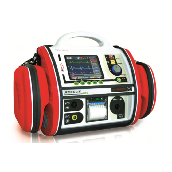
(BLS) and advanced life support (ALS) patient management protocols. RESCUE LIFE is designed to monitor the patient ECG signals and to deliver defibrillation shocks in MANUAL, ADVISORY or AED mode. This Operator’s Manual contains all the information that a user needs to operate the RESCUE LIFE properly. -
Page 8: Safety Instructions
GENERAL Assure yourself prior and after the use of the RESCUE LIFE that the unit is in safe and usable condition (cables integrity, pads, battery status). Assure that the battery charge , ECG trace, selected energy value, SYNC mode and status battery are well functioning. -
Page 9: Defibrillator
Rescue Life User Manual vers. 3.0 Feb. 2015 DEFIBRILLATOR EVER PUT IN CONTACT THE DEFIBRILLATOR PADDLES SHORT CIRCUIT EFIBRILLATION IN MANUAL MODE MUST BE PERFORMED ONLY BY HIGHLY TRAINED MEDICAL PERSONNEL E SURE THAT BOTH SURFACES OF THE SHOCK PADDLES ARE COMPLETELY MOISTENED WITH GEL... -
Page 10: Shock Or Fire Hazards
Rescue Life User Manual vers. 3.0 Feb. 2015 SHOCK OR FIRE HAZARDS The defibrillator delivers up to 230 joules of electrical energy. Unless properly used as described in these operating instructions, this electrical energy may cause serious injury or death. -
Page 11: Possible Device Shutdown Or Not Switching On
Rescue Life User Manual vers. 3.0 Feb. 2015 POSSIBLE DEVICE SHUTDOWN OR NOT SWITCHING ON Always check that the battery is fully charged. HEN OPERATING ON BATTERY POWER THE LARGE CURRENT DRAW REQUIRED FOR DEFIBRILLATOR CHANGING MAY CAUSE THE DEFIBRILLATOR TO REACH SHUTDOWN VOLTAGE LEVELS WITH NO LOW... -
Page 12: Symbols Used
Rescue Life User Manual vers. 3.0 Feb. 2015 SYMBOLS USED The symbols below may be found in this manual or rear sticker or accessories of Rescue Life defibrillator. Symbol Description Power ON/OFF button Charge button Status Led SHOCK button BF type, defibrillation proof equipment Attention: Refer to the User Manual. -
Page 13: Introduction
Be sure that you have all the required supplies and accessories including cables and ECG paper, when you remove the RESCUE LIFE defibrillator/monitor from the container used for the shipment. Verify the defibrillator and all accessories for any sign of damage that may have occurred during shipping. -
Page 14: Cleaning And Maintenance
Rescue Life User Manual vers. 3.0 Feb. 2015 CLEANING AND MAINTENANCE After each use, clean the defibrillator and the reusable pads using a soft, damp cloth moistened with any of the following solvents: Water and soap Clorexina and water mixture (30 ml clorexina/liter of water) -
Page 15: Connecting To Power
AC power cord. AC Operation The AC Mains LED illuminates, when the RESCUE LIFE defibrillator/monitor operates on AC power. When the defibrillator is not in use, maintain better the battery charge connecting the power cord to an AC outlet and turn off the defibrillator. -
Page 16: Battery Charge
When the message of the battery status displays a value under 70%, batteries should be charged. Insert the power supply cord in the RESCUE LIFE socket (located on the back side) and connect to the AC line. The battery status led will switch on. -
Page 17: Warranty
If unauthorized personnel render repairing service during the warranty period, this warranty becomes null and void. PROGETTI has no information regarding the performance or effectiveness of its RESCUE LIFE defibrillators if they are used with defibrillation electrodes or other parts and supplies from other sources. -
Page 18: Service
Rescue Life User Manual vers. 3.0 Feb. 2015 SERVICE We remind that only PROGETTI S.r.l. or its authorized representatives should service the device. If unauthorized personnel service the device during the warranty period, the warranty will become null and void. -
Page 19: Operational
ECG 'R' peak. The RESCUE LIFE in the basic configuration has only the manual mode available and the ECG monitoring can be done by defibrillation pads (1 trace) or by 5 leads ECG monitoring cable assembly from PROGETTI S.r.l. -
Page 20: Intended Use
Rescue Life User Manual vers. 3.0 Feb. 2015 INTENDED USE In manual mode the RESCUE LIFE is intended for use by health care professionals and emergency rescue personnel who have been trained in advanced cardiac life support. The user must know how to interpret ECG's, decide the energy level required and when the defibrillation is necessary. -
Page 21: Front Panel Description
Rescue Life User Manual vers. 3.0 Feb. 2015 FRONT PANEL DESCRIPTION SHOCK BUTTON CHARGE BUTTON SPEED DIAL STATUS BATTERY CHARGE LED FUNCTION ON / OFF KEYS SWITCH SHOCK BUTTON: Used to deliver the shock when using disposable pads. CHARGE BUTTON: Used to charge the energy selected when using disposable pads. -
Page 22: Front Panel Keys
To switch off the RESCUE LIFE press once the ON/OFF button. To power- off the device press the On-Off key only once. When the red light inside this key is on it means that RESCUE LIFE is SHOCK KEY ready to defibrillate. Pressing this key will release the defibrillation (DEFIBRILLATION) shock.(This key is active only when disposable pads are used). -
Page 23: Function Keys (F1-F5)
Rescue Life User Manual vers. 3.0 Feb. 2015 FUNCTION KEYS (F1-F5) START SCREEN OPERATIONAL SCREEN PACEMAKER MENU Select the pace maker rhythm. To set START DISARM the requested rhythm use the Speed operation internal discharge dial. PRINT Select pace maker current. Set the start/stop printing current intensity using the Speed Dial. -
Page 24: Start Screen Interface
DATE AND TIME SETUP To set-up the real time clock, switch on the RESCUE LIFE with at least one pad disconnected. On the screen will be displayed the battery status, the date and time. The F5 key enables the clock set-up. -
Page 25: Operational Screen
Rescue Life User Manual vers. 3.0 Feb. 2015 OPERATIONAL SCREEN At power ON, if the pads are connected the RESCUE LIFE will start the operation. If the pads are not connected the start screen will be displayed. ALARM BATTERY HEART... -
Page 26: Set-Up Menu
Rescue Life User Manual vers. 3.0 Feb. 2015 SET-UP MENU The START-UP menu is accessible pressing the F5 key (MENU) on the operational screen and all the values can be changed using the Speed Dial. Pressing the Speed Dial will select the field to change and rotating the Speed dial will change the field value. -
Page 27: Speed Dial Use
Rescue Life User Manual vers. 3.0 Feb. 2015 SPEED DIAL USE The Speed Dial allows to set the main parameters displayed in the right side of the screen. Press the Speed Dial in order to highlight them. When a parameter has been selected, rotate the Speed Dial for changing its value. -
Page 28: Connections
DEFIBRILLATION PADS It connects the defibrillation pads lead (APEX,STERNUM) to DEFIBRILLATION RESCUE LIFE. For connecting the lead, push in the connector and PADS INPUT turn it right. For disconnecting the lead, pull the lead lever and turn left the connector. -
Page 29: Device And Patient Preparation
Rescue Life User Manual vers. 3.0 Feb. 2015 DEVICE AND PATIENT PREPARATION PRODUCT CHECK Check carefully the content of the packing for any damage that might have been occured during shipping. Check carefully all the accessories to ensure that the unit comes with the complete accessories necessary for a proper use of the device. -
Page 30: How To Use The Ecg Patient Cable Connection And Electrodes Placement
Rescue Life User Manual vers. 3.0 Feb. 2015 HOW TO USE THE ECG PATIENT CABLE CONNECTION AND ELECTRODES PLACEMENT The ECG (electrocardiogram) is a recording of the electrical activity of the heart. The ECG is obtained by placing either electrodes or paddles on the patient and allows the heart’s electrical activity to be monitored and recorded. - Page 31 Rescue Life User Manual vers. 3.0 Feb. 2015 Precordial lead electrodes sites for the 10 wires ECG cable:...
-
Page 32: Defibrillation Therapy
A direct current defibrillator applies a brief, intense pulse of electricity to the heart muscle. The Rescue Life defibrillator/monitor delivers this energy through disposable pads, standard paddles or internal paddles applied to the patient’s chest. Successful resuscitation is associated to the length of time between the onset of a heart rhythm that does not circulate blood (ventricular fibrillation, pulseless ventricular tachycardia) and defibrillation. -
Page 33: How To Prepare The Patient
Rescue Life User Manual vers. 3.0 Feb. 2015 HOW TO PREPARE THE PATIENT Evaluate the patient condition; he must exhibit the symptoms for which the defibrillation is indicated and these symptoms are: Unconsciousness Absence of normal breathing Lack of detectable pulse. -
Page 34: How To Prepare The Pediatric Patient
Rescue Life User Manual vers. 3.0 Feb. 2015 HOW TO PREPARE THE PEDIATRIC PATIENT Open the package by tearing along the dotted line near the end of the pack. Remove the pads from the package and follow the directions and the schema for the correct placement of defibrillation electrodes placed on the packaging of the defibrillation electrodes and on the electrodes. -
Page 35: Defibrillation
Rescue Life User Manual vers. 3.0 Feb. 2015 DEFIBRILLATION DEFIBRILLATION PROCEDURE IN MANUAL OR ADVISORY (ADV) MODE 1. Switch on the device pressing the ON/OFF button. Connect and lock the pads plug to start the operation. The ECG signal will be displayed and by default the energy is set to 150 J. - Page 36 Rescue Life User Manual vers. 3.0 Feb. 2015 SYNC HEN USING MODE MAKE SURE THAT THE TRACE HAS A STABLE BASE LINE AND THE HEART SYNC RATE IS STABLE EFIBRILLATING IN MODE WITH A DISTURBED SIGNAL IS DANGEROUS ‘R’ BECAUSE THE MACHINE WILL NOT BE ABLE TO IDENTIFY CORRECTLY THE...
-
Page 37: Automated External Defibrillation (Optional)
INDICATIONS FOR USE The RESCUE LIFE with the semiautomatic option is intended to be used by personnel who have been trained in its operation. The operator should be qualified by training in basic life support, CPR/AED. The device is indicated for emergency treatment of victims exhibiting the following symptoms of a sudden cardiac arrest: un-consciousness, absence of normal breathing and lack of detectable pulse. -
Page 38: Ecg Analysis Algorithm
Resuscitation and Emergency Cardiovascular Care with Treatment Recommendations (CoSTR). Upon detecting a shockable cardiac rhythm, the RESCUE LIFE charges automatically at a 200J energy level and advises the operator to press the SHOCK button to deliver a shock; then advises the operator to check the patient pulse and start CPR for 120 seconds with a chest compression to ventilation ratio of 30:2. -
Page 39: Audio And Text Prompts
Rescue Life User Manual vers. 3.0 Feb. 2015 AUDIO AND TEXT PROMPTS PROMPTS MEANING Indicates that you have to connect the pads to the CONNECT PADS defibrillator. Indicates that the user have to attach the defibrillator ATTACH PADS electrode pads to the bare chest of the patient... -
Page 40: Semiautomatic (Aed) Mode Flow Chart
Rescue Life User Manual vers. 3.0 Feb. 2015 SEMIAUTOMATIC (AED) MODE FLOW CHART CONNECT PADS ATTACH PADS ANALYZING HEART RHYTHM NO SHOCK SHOCK ADVISED ADVISED NO SHOCK SHOCK DO CPR CHECK PULSE CPR 120 sec... -
Page 41: Pacemaker (Optional)
Non-invasive pacing is indicated for symptomatic bradycardia in patients with a pulse. Contraindications Non-invasive pacing is contraindicated for the treatment of ventricular fibrillation and asystole. On the operational screen, pressing the F3 key (PACER) the RESCUE LIFE will open the pacemaker mode and will display the pacemaker menu. IMPORTANT If the paddles are not attached to the patient the machine will not enter the pacemaker mode. - Page 42 Rescue Life User Manual vers. 3.0 Feb. 2015 For setting the pacing rhythm press the F1 key and use the Speed Dial to change the value. For setting the pacing current press the F2 key and use the Speed Dial to change the value.
-
Page 43: Spo2 Monitoring
Rescue Life User Manual vers. 3.0 Feb. 2015 SpO2 MONITORING The SPO2 Module measures functional oxygen saturation in the blood. The measurement determines the oxygenated hemoglobin as a percentage of the hemoglobin that can transport oxygen. Pulse oximetry works by having light emitting... -
Page 44: Pulse Oximetry Sensors
Rescue Life User Manual vers. 3.0 Feb. 2015 PULSE OXIMETRY SENSORS The RESCUE LIFE is equipped with an SpO2 sensor that is designed to be used with a finger of the patient. Other sensors from the manufacturer could also be used with the RESCUE LIFE. -
Page 45: Nibp (Non Invasive Blood Pressure)
NIBP (NON INVASIVE BLOOD PRESSURE) INTRODUCTION The Rescue Life NIBP option is based on the Advantage A+ module platform available in the series of oscillometric OEM NIBP technologies from SunTech Medical. The Advantage series of OEM NIBP technologies provides the simplicity of the oscillometric technique of acquiring... -
Page 46: Terminology For Nibp
Rescue Life User Manual vers. 3.0 Feb. 2015 TERMINOLOGY FOR NIBP Oscillometry The oscillometric method of blood pressure measurement is a non-invasive method that monitors the amplitude of cuff pressure changes during cuff deflation to determine arterial blood pressure. The cuff pressure is first elevated above the patient systolic blood pressure level and the cuff begins to deflate at a certain rate. -
Page 47: Warnings & Precautions During The Nibp Mesurament
Interpretation of blood pressure measurements should be made only by a physician or trained medical staff. The Rescue Life NIBP module is designed to work with SunTech cuffs and hoses. The use of cuffs and hoses not supplied by SunTech may compromise performance and accuracy. - Page 48 Rescue Life User Manual vers. 3.0 Feb. 2015 Adverse Reactions Allergic exanthema (symptomatic eruption) in the area of the cuff may result, including the formation of urticaria (allergic reaction including raised edematous patches of skin or mucous membranes and intense itching) caused by the fabric material of the cuff.
-
Page 49: Operation
Rescue Life User Manual vers. 3.0 Feb. 2015 OPERATION CUFF SELECTION & PLACEMENT It is important to select the cuff size that is appropriate to the diameter of the patient’s upper arm. Use the Range Lines on the inside of the cuff to determine the correct size cuff to use. -
Page 50: Activation And Operation Of The Nibp Mode
ACTIVATION AND OPERATION OF THE NIBP MODE To activate the NIBP mode, press the ‘MENU’ (F5) key form the operational Rescue Life screen. On the menu window the first selection is the NIBP option. -
Page 51: Nibp Set-Up Menu
Rescue Life User Manual vers. 3.0 Feb. 2015 SET (F4): to enter the NIBP set up menu. EXIT (F5): to exit the NIBP and return to the defibrillator functions. NIBP SET-UP MENU Pressing the ‘SET’ (F5) key the NIBP set-up menu is displayed. - Page 52 Rescue Life User Manual vers. 3.0 Feb. 2015 Appendix 1 Error Code List & Definitions If more than one error occurs during a single measurement, the higher numbered error code will be displayed. EC 1 Weak or no oscillometric signal Corrective Action: Check that the cuff is in the correct position.
- Page 53 Rescue Life User Manual vers. 3.0 Feb. 2015 C or r ect i ve A ct i on: C h eckt h e p a t i ent . C h eckt h a tt h e cu ff i s i n t h e cor r ectp osi t i on.
- Page 54 Rescue Life User Manual vers. 3.0 Feb. 2015 Appendix 2 Accessory Parts Part # Description Special Instructions 91-0032-02 3 meter Patient Hose w/CPC connectors 98-0080-01 APC Cuff, Infant Range: 8 – 13 cm 98-0080-02 APC Cuff, Child Range: 12 – 19 cm...
- Page 55 Rescue Life User Manual vers. 3.0 Feb. 2015 Appendix 3 Specifications Method of Measurement: Oscillometric. Diastolic values correspond to Phase 5 Korotkoff sounds. Blood Pressure Range: Systolic: ADULT 40 – 260mmHg PEDIATRIC 40 – 160mmHg NEONATE 40 – 130mmHg MAP: ADULT 26 –...
- Page 56 Rescue Life User Manual vers. 3.0 Feb. 2015 0C to 50C, 15% to 95% non-condensing humidity Storage Conditions: -20C to 65C, 15% to 90% non-condensing humidity Altitude: Measurement accuracy is not affected by altitude Auto Interval Periods: 1, 2, 3, 4, 5, 10, 15, 30, 60 and 90 minutes...
-
Page 57: Data Base
In AED mode the recording will start automatically each time the ANALISYS starts. When RESCUE LIFE is recording, on the top side of the graphic window (display) a red line advances together with the ECG graph (for 1 minute which is the Record length). - Page 58 Rescue Life User Manual vers. 3.0 Feb. 2015 if the PRINT key is pressed again. The EXIT (F5) key is used to go back from the graphic to record selection and to the files list. The DELETE (F4) key is used to cancel the content of the selected file. The file name is not canceled but only the records present in the file.
-
Page 59: Data Base Screen
Rescue Life User Manual vers. 3.0 Feb. 2015 DATA BASE SCREEN FILE NUMBER REGISTRATIO FILE DATE 0000001 0000001 01/01/00 0000002 01/01/00 0000003 01/01/00 0000004 01/01/00 FREE MEMORY: 166666 Min, 2777 hours PG DOWN TOP PG PRINT DELETE EXIT SCROLL PAGE... -
Page 60: Printing And Paper Change
To stop the printing, press again the PRINT (F2) key. IN AUTOMATIC MODE RESCUE LIFE will print an ECG frame of 6 seconds when the charge starts. When the shock is released the energy delivered, as well as the time stamp will be printed together with a 6 seconds after shock ECG frame. -
Page 61: Clinical Information
Rescue Life User Manual vers. 3.0 Feb. 2015 APPENDIX CLINICAL INFORMATION Sudden cardiac arrest (SCA) associated with ventricular fibrillation (VF) remains a leading cause of unexpected death in the Western world. It has been estimated that chances for survival from SCA decrease approximately 7% to 10% with each passing minute and that survival rates after 12 minutes are only 2% to 5%. -
Page 62: Ease In Compensation Of Patient Impedance
Rescue Life User Manual vers. 3.0 Feb. 2015 cause damage to the cells and result in an unsuccessful defibrillation. Too little current to the myocardial tissue cells will not depolarize the cells and result in an unsuccessful defibrillation. The waveform biphasic technology:... - Page 63 Rescue Life User Manual vers. 3.0 Feb. 2015...
- Page 64 Rescue Life User Manual vers. 3.0 Feb. 2015 Extensive animal and human data with implanted devices demonstrate that biphasic waveforms offer substantial reductions in defibrillation thresholds and produce less myocardial dysfunction than monophasic waveforms. [1], [2], [3], [4] The defibrillation efficacy of the 150-J biphasic waveform was superior to that of the 200-J to 360-J conventional escalating-energy monophasic waveforms for 115 patients who presented with VF.
- Page 65 Rescue Life User Manual vers. 3.0 Feb. 2015 The difference between monophasic and biphasic waveform is qualitatively similar but varies quantitatively for different parameter values. The fundamental difference is that first phase of the biphasic pulse acts as a pre-pulse to remove inactivation from the heart cell, accelerating its recovery, and thereby lowering the activation threshold for defibrillation prior to second phase of biphasic pulse which is reversed current flow.
-
Page 66: References
Rescue Life User Manual vers. 3.0 Feb. 2015 REFERENCES 1.Chapman PD, Vetter JW, Souza JJ, Wetherbee JN, Troup PJ. Comparison of monophasic with single and dual capacitor biphasic waveforms for nonthoracotomy canine internal defibrillation. J Am Coll Cardiol. 1989;14:242.5. 2. Kavanagh KM, Tang ASL, Rollins DL, Smith WM, Ideker RE. -
Page 67: Technical Specifications
Rescue Life User Manual vers. 3.0 Feb. 2015 APPENDIX C TECHNICAL SPECIFICATIONS Waveform time-impedance Following flow-charts show typical defibrillation impulses considering the impedance between the defibrillation electrodes for a maximum of 230 Joule: 150J, 25ohm 230J,50ohm 230J,75ohm 230J,100ohm 230J,125ohm 230J,150ohm... -
Page 68: Impendance Limits
For impedance of 50 ohm the accuracy is +/- 10%. IMPENDANCE LIMITS RESCUE LIFE does not release the shock if the patient impedance is less than 20 ohm or over 200 ohm. SYNC/NO SYNC MODE When the RESCUE LIFE is on it is automatically set on no-sync mode. -
Page 69: Technical Features
Rescue Life User Manual vers. 3.0 Feb. 2015 TECHNICAL FEATURES ECG Monitoring • Patient connection : Defibrillation pads • Bandwidth: 0.5 to 120 Hz (-3 dB) with filters off • ECG trace parameters: Velocity : 5,10,25, 50 mm/sec Gain: 2,5, 5, 10, 20, 40 mm/mV with patient cable. AUTO with pads. - Page 70 Rescue Life User Manual vers. 3.0 Feb. 2015 Manual mode • Energy range: 1 – 230 J (from 1 – 10 J in 1 J steps; from 10 – 230 J in 10 J steps) • Commands: Multifunction Trim Knob. Charge and shock button directly in the front panel for hands free defibrillation •...
- Page 71 Rescue Life User Manual vers. 3.0 Feb. 2015 Printer • Type: Integrated thermal printer for ECG traces and events documentation hardcopy including HR/SpO2 values • Paper Speed: 5, 10, 25 mm/sec • Paper width: 58 mm • Operating model: Manual, automatic (10” pre and post shock recording) External pacemaker (optional) •...
-
Page 72: Ce Declaration Of Conformity
LAW, THE PROVISIONS OF COUNCIL DIRECTIVE 93/42/EEC OF 14 JUNE 1993 CONCERNING MEDICAL DEVICES. SUPPORTING DOCUMENTATION RETAINED PREMISES MANUFACTURER. FOR DEDICATED DECLARATION OF CONFORMITY WITH YOUR DEVICE’S SERIAL NUMBER CONTACT PROGETTI OFFICE NOTIFIED BODY : ISTITUTO DI RICERCHE E COLLAUDI M. MASINI S.r.l. Via Moscova, 11 20017 Rho - MI, ITALY... -
Page 73: Warranty Certificate
PROGETTI S.r.l.. This warranty does not cover any accessories. PROGETTI S.r.l. will replace damaged parts and components, according to its option. PROGETTI S.r.l. will replace cost free those parts and components under guarantee in its laboratory. CLIENT:... - Page 76 Rescue Life User Manual vers. 3.0 Feb. 2015 www.progettimedical.com...
Need help?
Do you have a question about the Rescue Life and is the answer not in the manual?
Questions and answers