
Related Manuals for DANIEL 1200 Series


Summary of Contents for DANIEL 1200 Series
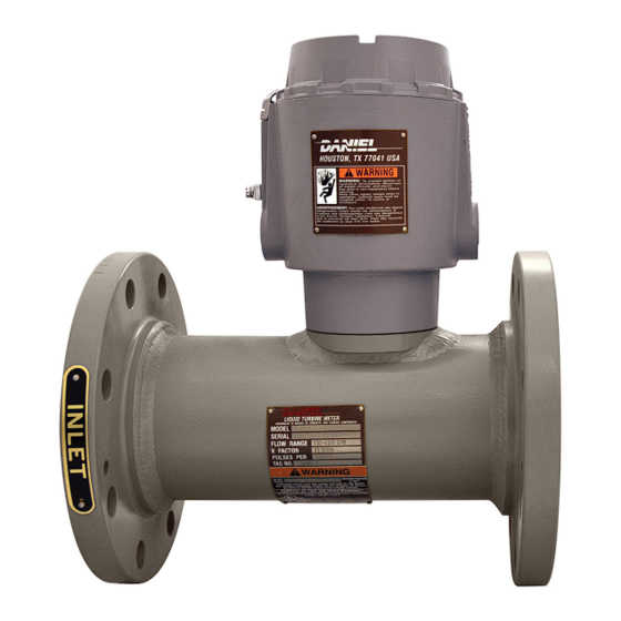
- Page 1 DANIEL ® LIQUID TURBINE METER USER MANUAL SERIES 1200 LIQUID TURBINE METER NPS 1 THROUGH 4 Decades Proven. Field Chosen. ™ OCTOBER 2022...
-
Page 2: Table Of Contents
5.2 Torque information........................53 5.3 Tools required for LME disassembly/assembly................53 Chapter 6 Installation procedure....................55 6.1 Cathodic protection........................55 6.2 Mechanical components assembly.................... 55 6.3 Assemble the electronic components..................56 Chapter 7 Testing........................59 7.1 Test the turbine meter....................... 59 Part III Operate www.Daniel.com User manual... - Page 3 10.2 Verify the return to operational condition................91 Chapter 11 Spare parts.......................93 11.1 Recommended spare parts...................... 93 Chapter 12 Decommission the turbine meter................95 12.1 Shut down the turbine meter....................95 12.2 Turbine meter disassembly/assembly..................95 12.3 Shipment of the meter......................96 www.Daniel.com Daniel Series 1200 Liquid Turbine Meter...
-
Page 4: Part I Plan
User manual Plan SERIES 1200 LIQUID TURBINE METER P/N 3-9008-513 September 2020 Part I Plan www.Daniel.com User manual... -
Page 5: Chapter 1 Introduction
Introduction Purpose of this manual Daniel designed this manual to guide owners and personnel in the installation, operation and maintenance of the Daniel Series 1200 Liquid Turbine Meter Manual, 3-9008-513. It is imperative that product owners and operation personnel read and follow the information contained in this manual to ensure that the turbine meter is installed correctly and is operating according to the design, certifications and safety considerations. - Page 6 Failure to comply may result in personnel injury. WARNING RISK TO PERSONNEL AND EQUIPMENT Failure to follow the installation, operation or maintenance instructions for a Daniel product could lead to serious injury or death from explosion or exposure to dangerous substances. To reduce the risk: •...
-
Page 7: Warranty Restrictions
Daniel assumes no responsibility for incidents, or consequences of incidents, occurring as a result of the use of this product by others than Daniel or its designated personnel, and have no liability whatsoever for any such work. -
Page 8: Description Of The Series 1200 Liquid Turbine Meter (Ltm)
1.6.1 General features of the turbine meter The Daniel Series 1200 Liquid Turbine Meter (LTM) is a volumetric flow metering and transmitting device used extensively in the petroleum industry for the accurate measurement of liquid hydrocarbons. The turbine meter's simple configuration ensures higher flow rates, extended flow range and sustained performance capability. - Page 9 • All Daniel Series 1200 Liquid Turbine Meters have, as standard, the LME which is fitted with two pickoffs and a dual channel preamplifier. •...
- Page 10 SERIES 1200 LIQUID TURBINE METER Introduction User manual September 2020 P/N 3-9008-513 LME assembly - Standard enclosure Figure 1-1: Part identification for a standard enclosure www.Daniel.com...
- Page 11 The joint between the LME cover and housing is a threaded joint. The joint between the LME housing and Sensor housing is a spigot joint with a minimum axial length of 26.16 mm (1.030 in), radial length of 3.18 mm (0.125 in), and a clearance of 0.07 mm (0.0028 in). www.Daniel.com...
- Page 12 SERIES 1200 LIQUID TURBINE METER Introduction User manual September 2020 P/N 3-9008-513 LME assembly - Internal Totalizer Figure 1-2: Part identification for the LME with Internal Totalizer www.Daniel.com...
- Page 13 The joint between the LME cover and housing is a threaded joint. The joint between the LME housing and sensor housing is a cylindrical joint which has an axial length of 25.4 mm (1 in) and a clearance of 0.038 mm (0.0015 in). www.Daniel.com...
- Page 14 SERIES 1200 LIQUID TURBINE METER Introduction User manual September 2020 P/N 3-9008-513 Meter housing internal components - NPS 1 The information below identifies and describes the NPS 1 meter housing components. Figure 1-3: Part identification for an NPS 1 LTM www.Daniel.com...
- Page 15 Hanger blade 798-10-080-00 Hanger hub 798-10-008-00 Shaft 798-10-018-00 Bearing 1505024 Spacer 798-10-073-00 Pickoff 899-00-201-00 Meter housing Class 150 799-10-311-61M 1 Class 300 799-10-331-61M 1 Anti-rotation bracket clamp 899-10-230-66 Note For alternative materials and NACE, contact Daniel Sales and Service. www.Daniel.com...
- Page 16 User manual September 2020 P/N 3-9008-513 Meter housing internal components - NPS 1.5 through 2 The information below identifies and describes the NPS 1.5 through 2 meter housing components. Figure 1-4: Part identification for an NPS 1.5 through 2 LTM www.Daniel.com...
- Page 17 Washer 151891 Flow conditioning plate 798-16-301-01 Hanger blade 798-16-070-00 Hanger hub 798-16-308-00 Bearing 155195 Spacer 798-14-073-00 Rotor 798-16-019-00 Downstream cone 798-16-013-00 O-ring 1500093-022 Pickoff 899-00-201-00 Meter housing Class 150 798-16-312-61M 1 Class 300 798-16-332-61M 1 Anti-rotation bracket clamp 899-10-230-66 www.Daniel.com...
- Page 18 SERIES 1200 LIQUID TURBINE METER Introduction User manual September 2020 P/N 3-9008-513 Note For alternative materials and NACE, contact Daniel Sales and Service. www.Daniel.com...
- Page 19 Meter housing internal components - NPS 3 through 4 - Stainless steel bearing internals The information below identifies and describes the NPS 3 through 4 stainless steel meter housing components. Figure 1-5: Part identification for an NPS 3 through 4 LTM - Stainless steel bearing internals www.Daniel.com...
- Page 20 Table 1-7: Part description for an NPS 4 LTM - Stainless steel bearing internals Item Description Part number Quantity number required 151685 Flow Conditioning 798-22-301-01 Plate - Thermoplastic Flow Conditioning 788-22-301-02 Plate - Aluminum Rotor assembly 798-22-319-00 www.Daniel.com Daniel Series 1200 Liquid Turbine Meter...
- Page 21 (External, Bowed) Shaft 798-22-010-00 Roll pin 153505-419 Retaining ring 1500617 Retaining Ring 1500734 (External) Meter housing Class 150 798-22-312-61M 1 Class 300 798-22-332-61M 1 Anti-rotation bracket clamp 899-10-230-66 Note For alternative materials and NACE, contact Daniel Sales and Service. www.Daniel.com...
- Page 22 Meter housing internal components - NPS 3 through 4 - Tungsten carbide bearing internals The information below identifies and describes the NPS 3 through 4 tungsten carbide meter housing components. Figure 1-6: Part identification for an NPS 3 through 4 LTM -Tungsten carbide bearing internals www.Daniel.com...
- Page 23 Table 1-9: Part description for an NPS 4 LTM -Tungsten carbide bearing internals Item Description Part number Quantity number required 151685 Flow Conditioning 798-22-301-01 Plate - Thermoplastic Flow Conditioning 788-22-301-02 Plate - Aluminum Rotor assembly 798-22-319-01 O-ring 1500093-022 Washer 151891 Diffuser 798-22-390-00 Support fin 798-22-070-00 www.Daniel.com User manual...
- Page 24 Thrust washer 894-22-062-00 Outlet diffuser cap 798-22-013-00 Belleville washer 1500422 151650 Cotter pin 153930 Meter housing Class 150 798-22-312-61M 1 Class 300 798-22-332-61M 1 Anti-rotation bracket clamp 899-10-230-66 Note For alternative materials and NACE, contact Daniel Sales and Service. www.Daniel.com...
-
Page 25: Agency Certifications For The Series 1200 Ltm
Introduction USER MANUAL P/N 3-9008-513 September 2020 Agency certifications for the Series 1200 LTM The following are product agency certifications applicable to the Daniel Series 1200 LTM. Table 1-10: Agency certifications for the Series 1200 LTM Certification type Description Certificate Electrical UL and CUL: Class I, Div. -
Page 26: Operating Conditions And Specifications
-40 ºC to 60 ºC (-40 ºF to 140 ºF) (Stainless steel flanges) Fluid static pressure The maximum working pressure for the Daniel Series 1200 Liquid Turbine Meter is based on the temperature/ pressure rating of the ANSI B16.5 flanges. For maximum working pressures at intermediate temperatures refer to ANSI B16.5. - Page 27 Install the turbine meter in a well ventilated area, not less than and combustion sources one meter (approximately 3 feet) from source of ignition or source of heat which might damage the unit. Elevation No limit. Humidity No limit. www.Daniel.com Daniel Series 1200 Liquid Turbine Meter...
- Page 28 The ideal accuracy curve of a volumetric meter, such as the turbine, is a straight line denoting a constant meter factor. Cavitation is the formation and collapse of vapor-filled cavities that result from a sudden decrease and increase in pressure. Refer to Back pressure calculation for more information. www.Daniel.com User manual...
- Page 29 The metering system should have a flow rate control valve located at a convenient distance downstream of all measurement equipment. The function of the control valve is to limit and maintain system pressure on the meter. This avoids cavitation. www.Daniel.com Daniel Series 1200 Liquid Turbine Meter...
-
Page 30: Specifications For The Ltm
Table 2-3: 2818 Dual channel preamplifier performance Parameter type Description Inputs Supply voltage: 10-30 VDC Sensor type: Reluctance Signal: Sine wave Preamplifier sensitivity: 40 mV peak to peak minimum Temperature range: -40 ºC to 85 ºC (-40 ºF to 185 ºF) www.Daniel.com User manual... - Page 31 The LME housing should be at earth ground. Table 2-4: 2818 Dual channel preamplifier configuration Plug component designator Terminal connections Description TB1 - Customer connection +10 to 30 Vdc Common Common Channel A output Channel B output www.Daniel.com Daniel Series 1200 Liquid Turbine Meter...
- Page 32 It is important that the correct service manual be referenced before attempting to use accessories or instrumentation with the Series 1200 LTM. Contact the factory or nearest Daniel service office if service manuals were not received at the time of purchase or delivery.
- Page 33 Important A spool piece installed in place of the turbine meter is recommended for this procedure. NOTICE Comply with local government regulations and company requirements. www.Daniel.com...
- Page 34 Table 2-5: Flow meter and flow straightening section dimensions for the Series 1200 LTM NPS 1-4 Size Inches Inches Inches Table 2-6: Flow meter and flow straightening section dimensions for the Series 1200 LTM NPS 1-4 Size Inches Inches Inches 1397 www.Daniel.com User manual...
- Page 35 Table 2-6: Flow meter and flow straightening section dimensions for the Series 1200 LTM NPS 1-4 (continued) Size Inches Inches Inches 1016 1829 Table 2-7: Weight table for the stainless steel LME Size ANSI class 150 ANSI class 300 www.Daniel.com Daniel Series 1200 Liquid Turbine Meter...
-
Page 36: Turbine Meter Handling
1. Use stretch wrap (not adhesive) to attach the correct size flange cover to the turbine meter end flanges. This protects the unpainted surfaces of the flange sealing. 2. A flush contact between the flange cover and the flange sealing face is important. www.Daniel.com User manual... - Page 37 Do not remove nameplates or labels. Doing so will void the turbine meter warranty. Stacking When stacking equipment, follow all safety standards, taking into account the type of box used, the maximum height of the equipment, the maximum number of boxes stacked, etc. www.Daniel.com Daniel Series 1200 Liquid Turbine Meter...
-
Page 38: Prepare The Turbine Meter For Use
WARNING LIFTING HAZARD The lifting instructions are for installation and removal of the Daniel Liquid Turbine Meter only and do not address lifting the turbine meter while it is attached or bolted to piping. Failure to comply with these instructions may result in death, serious injury, or equipment damage. -
Page 39: Lifting Requirements For Personnel
Best lifting practices WARNING LIFTING HAZARD The lifting instructions are for installation and removal of the Daniel Liquid Turbine Meter only and do not address lifting the turbine meter while it is attached or bolted to piping. Failure to comply with these instructions may result in death, serious injury, or equipment damage. - Page 40 SERIES 1200 LIQUID TURBINE METER P/N 3-9008-513 September 2020 Safety precautions using appropriately rated lifting slings When lifting a liquid turbine meter by itself, Daniel recommends using lifting slings appropriately positioned at designated areas of the turbine meter. WARNING LIFTING HAZARD...
- Page 41 Doing this may cause injury and/or damage the equipment. • Never apply shock loads to the turbine meter. Always lift the turbine meter gradually. If shock loading occurs, inspect the slings per manufacturer's recommendations prior to further use. www.Daniel.com Daniel Series 1200 Liquid Turbine Meter...
-
Page 42: Configuration Of The Turbine Meter
Prepare the turbine meter for use SERIES 1200 LIQUID TURBINE METER P/N 3-9008-513 September 2020 Configuration of the turbine meter The Daniel factory configures the turbine meter internal components. Inspect the internal components before installation. 4.3.1 Orientation and position of the turbine meter Flow direction Turbine meters can be used for uni-directional flows. - Page 43 Provide fire prevention measures and equipment per local regulations. 4.3.3 Calibration options for the turbine meter Daniel offers a standard six-point calibration (from 10% to 100%); or can provide other customer requested calibration data. Table 4-2: Standard calibration for a Daniel Liquid Turbine Meter...
- Page 44 LME as the primary ground. A secondary ground is located outside of the LME. Refer to Figure 4-4 Figure 4-5. Digital grounds should never be connected to chassis ground. Figure 4-4: External ground lug A. External ground lug www.Daniel.com...
- Page 45 Security seals protect the integrity of the turbine meter metrology and prevent tampering with the preamplifier and pickoffs. The section below details how to properly seal the Daniel 1200 LTM after commissioning. The security seal wires are commercially available. www.Daniel.com...
- Page 46 (maximum wire diameter 2.0 mm, .078 inch). 3. Adjust the security wire, removing all slack and thread into the lead seal. 4. Cut the ends of the wire to remove any excess wire. www.Daniel.com...
-
Page 47: Part Ii Install
User manual USER MANUAL Install P/N 3-9008-513 September 2020 Part II Install www.Daniel.com User manual... -
Page 48: Chapter 5 Installation Prerequisites
• 6 mm Allen key • 3 mm Allen key • 2.5 mm Allen key • 3/32 Allen key • 10 mm Allen key • Phillips screwdriver • 3.5 mm Flathead screwdriver • 10 mm Flathead screwdriver www.Daniel.com User manual... -
Page 49: Chapter 6 Installation Procedure
Property class of the fastener is in accordance with ASME B16.5. Stud bolt and nut types All fasteners (nuts and studs) used in assembling Daniel turbine meters are made of one of the materials listed in the table below. Table 6-2: Bolt material selection... -
Page 50: Assemble The Electronic Components
Remove each nut and bolt as a pair. Thread the matching nut back onto the bolt. Stack them in a fashion that will not cause thread damage. Reuse of flange stud bolts and nuts Daniel Quality Control permits the reuse of threaded fasteners under the following conditions: •... - Page 51 5. Install the electronics according to Wiring and cable connections. Consult with Daniel if the preamplifier acquired is other than a dual channel preamplifier. WARNING SHOCK AND EXPLOSION HAZARD Verify that the LME and/or RME is grounded.
-
Page 52: Chapter 7 Testing
3. Evaluate the system setup to ensure that all components are in the correct sequence for accurate product measurement: isolation valve, strainer, flow straightener, turbine meter, downstream section, control valve, etc. 4. Ensure that the supply voltage to the preamplifier is within the 10-30 VDC range. www.Daniel.com User manual... - Page 53 USER MANUAL User manual Operate P/N 3-9008-513 September 2020 Part III Operate www.Daniel.com User manual...
-
Page 54: Chapter 8 Operation Parameters
Operation parameters Operation overview The Daniel Series 1200 LTM is a volumetric flow measuring and transmitting device that produces an output signal proportional to the rate-of-flow of the liquid being measured. The primary output is a single or dual high resolution signal that is amplified and shaped by an integral preamplifier mounted within an explosion proof housing. - Page 55 Note temperature limitations when selecting turbine meter location. Important Always use a flushing medium that is compatible with the metallurgy of the meter, internal components. Using water as a flushing medium may result in damage to the internal components of the turbine meter. www.Daniel.com...
-
Page 56: Part Iv Maintain
SERIES 1200 LIQUID TURBINE METER User manual Maintain P/N 3-9008-513 September 2020 Part IV Maintain www.Daniel.com User manual... -
Page 57: Chapter 9 Planned Maintenance
Use the following tools for turbine meter disassembly: • Needle nose pliers • Torque wrench (dependant on size) • Ratchet with correspondent hex socket (dependant on size), or screwdriver with hexagonal tip • 3 mm Allen key • 3.5 mm flathead screwdriver • Mallet www.Daniel.com User manual... -
Page 58: Prepare For Mechanical Disassembly
6. Disconnect conduit connections to the turbine meter. 7. Remove turbine meter from line. Refer to Lifting equipment Lifting conditions, Lifting requirements for personnel, and Safety precautions using appropriately rated lifting slings for instructions on lifting the turbine meter. www.Daniel.com Daniel Series 1200 Liquid Turbine Meter... - Page 59 2. Remove the sleeve. You may need to GENTLY tap the internals from the downstream end using a soft punch to start the process. Figure 9-2: Sleeve removal 3. Carefully remove the upstream sleeve. This is one piece. www.Daniel.com User manual...
- Page 60 Figure 9-4: Internals of the meter 9.3.2 Disassemble internal meter housing components - NPS 1.5 through 2 Procedure 1. Remove the nut, washer and flow conditioning plate by pulling the parts from the center bolt. www.Daniel.com Daniel Series 1200 Liquid Turbine Meter...
- Page 61 3. Gently remove the internals from the flow tube. Figure 9-6: Internals removal 4. Remove the nut from the downstream (rotor) end of the internal bullet after laying the support fins aside. www.Daniel.com...
- Page 62 The ball races are a loose fit in recesses on the rotor hub and may fall out. Be careful not to lose any small parts. Figure 9-8: Downstream stator and rotor removal 6. Disassemble all the internals. Figure 9-9: Internals disassembly www.Daniel.com Daniel Series 1200 Liquid Turbine Meter...
- Page 63 Push the shaft flush with the support fins and lift the fins slightly to remove them from the groove inside the flow tube. 3. Gently remove the internals from the flow tube. www.Daniel.com User manual...
- Page 64 There is an etched “U” on the upstream side of the rotor. Important Handle the rotor with care. Improper handling of the rotor assembly may cause distortion to the rotor blades thereby affecting meter performance. www.Daniel.com Daniel Series 1200 Liquid Turbine Meter...
- Page 65 Figure 9-14: Internal retaining ring removal 4. Remove the bearing assembly from the diffuser. Disassembly is complete. Figure 9-15: Bearing assembly removal 5. Remove the bearing assembly retaining rings to inspect and/or replace the individual ball bearing units if necessary. www.Daniel.com...
- Page 66 Figure 9-17: Cotter pin removal 2. Remove the castle nut from the shaft. Figure 9-18: Castle nut removal 3. Remove the outlet diffuser cap and Belleville washers. www.Daniel.com Daniel Series 1200 Liquid Turbine Meter...
- Page 67 Figure 9-21: Rotor removal 6. Remove the shaft sleeve from the bearing shaft. Figure 9-22: Shaft sleeve removal 7. Remove the upstream thrust washer. Note that the slot faces the rotor. Disassembly is complete. www.Daniel.com...
-
Page 68: Mechanical Assembly
Handle the rotor with care. Improper handling of the rotor assembly may cause distortion to the rotor blades thereby affecting meter performance. Figure 9-24: Internals assembly 2. Install the sleeve. www.Daniel.com Daniel Series 1200 Liquid Turbine Meter... - Page 69 The ball races are a loose fit in recesses on the rotor hub and may fall out. Be careful not to lose any small parts. Install the downstream stator and rotor into the bolt. www.Daniel.com User manual...
- Page 70 Figure 9-27: Internals assembly 2. Install the support fins and nut from the downstream (rotor) end into the internal bullet. Figure 9-28: Support fins and nut installation 3. Gently install the internals into the flow tube. Figure 9-29: Internals installation www.Daniel.com...
- Page 71 Stainless steel bearing internals assembly Procedure 1. Remove the bearing assembly retaining rings to inspect and/or replace the individual ball bearing units if necessary. Figure 9-31: Bearing assembly retaining rings removal 2. Install the bearing assembly into the diffuser. www.Daniel.com...
- Page 72 Handle the rotor with care. Improper handling of the rotor assembly may cause distortion to the rotor blades, affecting meter performance. Figure 9-34: Rotor installation 5. Install the retaining ring and support fins to the end of the bearing supporting the rotor. www.Daniel.com...
- Page 73 6. Gently install the internals into the flow tube. Figure 9-36: Internals installation 7. Lightly tap the center bolt from the downstream rotor end with a soft-faced mallet to tighten the compression on the support fins. 8. Install the nut, washer and flow conditioning plate if necessary. www.Daniel.com...
- Page 74 Tungsten carbide bearing internals assembly Procedure 1. Install the upstream thrust washer. Note that the slot faces the rotor. Figure 9-38: Upstream thrust washer installation 2. Install the shaft sleeve from the bearing shaft. Figure 9-39: Shaft sleeve installation www.Daniel.com...
- Page 75 4. Install the downstream thrust washer from the shaft. Note that the slot faces the rotor. Figure 9-41: Downstream thrust washer installation 5. Install the outlet diffuser cap and Belleville washers. Figure 9-42: Diffuser cap and Belleville washers installation 6. Install and tighten the castle nut into shaft. www.Daniel.com...
- Page 76 7. Install the support fins and cotter pin into the castle nut. Note Do not turn the nut counterclockwise to align the cotter pin hole. The nut must be tight on the shaft. Figure 9-44: Cotter pin and support fins installation 8. Gently install the internals into the flow tube. www.Daniel.com...
- Page 77 9. Lightly tap the center bolt from the downstream rotor end with a soft-faced mallet to tighten the compression on the support fins. 10. Install the nut, washer and flow conditioning plate if necessary. Figure 9-46: Nut, washer and flow conditioning plate installation www.Daniel.com...
-
Page 78: Electronics Enclosure Disassembly
LME housing and Sensor housing is a spigot joint with a minimum axial length of 26.16 mm (1.030 in), radial length of 3.18 mm (0.125 in), and a clearance of 0.07 mm (0.0028 in). www.Daniel.com Daniel Series 1200 Liquid Turbine Meter... -
Page 79: Replace The Preamplifier
8. Attach electrical output wiring from electrical accessories (conduit wiring) to terminal connection TB1, number 3 for channel A, and number 5 for channel B. 9. Secure all electrical wiring. 10. Secure screws of preamplifier bracket in to the enclosure. 11. Return cover and secure. www.Daniel.com... -
Page 80: Planned Maintenance Tasks
A careful review of turbine meter proving history, such as turbine meter factor control charts, can reveal potential problems with turbine meter measurements. Examples include bearing drag due to wear or an increased internal cross-sectional area due to erosion. www.Daniel.com Daniel Series 1200 Liquid Turbine Meter... -
Page 81: Chapter 10 Corrective Maintenance
September 2020 Corrective maintenance 10.1 Turbine meter troubleshooting Use the table below to troubleshoot the turbine meter. Contact the nearest Daniel service office for repairs. It is important that servicing be performed by trained and qualified service personnel. Table 10-1: Troubleshooting... - Page 82 3. Evaluate the system setup to ensure that all components are in the correct sequence for accurate product measurement: isolation valve, strainer, flow straightener, turbine meter, downstream section, control valve, etc. 4. Ensure that the supply voltage to the preamplifier is within the 10-30 VDC range. www.Daniel.com...
-
Page 83: Chapter 11 Spare Parts
USER MANUAL User manual Spare parts P/N 3-9008-513 September 2020 Spare parts 11.1 Recommended spare parts The figure below identifies the spare parts for an LME assembly. Figure 11-1: Part identification for a standard enclosure www.Daniel.com User manual... - Page 84 Refer to Interface parameters for detailed preamplifier information. Refer toLME assembly - Standard enclosure Order spare parts Contact Daniel Flow customer service and provide the following information when ordering spare parts: • Turbine meter serial number • Part number •...
-
Page 85: Decommission The Turbine Meter
Thoroughly clean the turbine meter inside the housing components and store or ship as it was received. Refer to Pack the turbine meter. After the meter is shut down, refer to Electronics enclosure disassembly Electronics enclosure assembly for the detailed disassembly/assembly procedures. www.Daniel.com User manual... -
Page 86: Shipment Of The Meter
SERIES 1200 LIQUID TURBINE METER Decommission the turbine meter User manual September 2020 P/N 3-9008-513 12.3 Shipment of the meter Refer to the Daniel Flow customer service information in the preface of this document. www.Daniel.com... - Page 87 Contact Us Email: Sales@Daniel.com Phone: +1 (346)-509-3700 Decades Proven. Field Chosen. ™ www.Daniel.com Copyright © 2022 Daniel Measurement and Control. All Rights Reserved. P/N 1-3-9008-513, Rev AH...
Need help?
Do you have a question about the 1200 Series and is the answer not in the manual?
Questions and answers