
Related Manuals for DANIEL 1500 Series


Summary of Contents for DANIEL 1500 Series
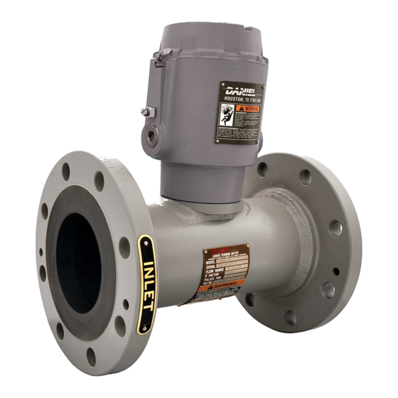
- Page 1 DANIEL ® LIQUID TURBINE METER USER MANUAL SERIES 1500 LIQUID TURBINE METER NPS 3 THROUGH 24 Decades Proven. Field Chosen. ™ OCTOBER 2022...
- Page 2 Notice is used to address safety messages or practices not related to personal injury. Important Important is a statement the user needs to know and consider. Tip provides information or suggestions for improved efficiency or best results. Note Note is “general by-the-way” content not essential to the main flow of information. www.Daniel.com...
- Page 3 To ensure safe and proper performance, only informed and trained personnel should install, operate, repair and maintain this product. • Verify that this is the correct instruction manual for your Daniel product. If this is not the correct documentation, contact Daniel at 1-713-827-6314. You may also download the correct manual from: https://www.Daniel.com/en-us/automation/ daniel.
- Page 4 Follow all warnings, cautions, and notices marked on, and supplied with, this product. • Verify that this is the correct instruction manual for your Daniel product. If this is not the correct documentation, contact • Daniel. You may also download the manual on www.Daniel.com.
- Page 5 WARRANTIES, EXPRESSED OR IMPLIED, INCLUDING THE IMPLIED WARRANTIES OF MERCHANTABILITY AND FITNESS FOR A PARTICULAR PURPOSE WITH RESPECT TO THIS MANUAL AND, IN NO EVENT, SHALL DANIEL BE LIABLE FOR ANY INCIDENTAL, PUNITIVE, SPECIAL OR CONSEQUENTIAL DAMAGES INCLUDING, BUT NOT LIMITED TO, LOSS OF PRODUCTION, LOSS OF PROFITS, LOSS OF REVENUE OR USE AND COSTS INCURRED INCLUDING WITHOUT LIMITATION FOR CAPITAL, FUEL AND POWER, AND CLAIMS OF THIRD PARTIES.
- Page 6 Daniel are not covered by this limited warranty, and shall be at Buyer's expense. Daniel shall not be obligated to pay any costs or charges incurred by Buyer or any other party except as may be agreed upon in writing in advance by Daniel. All costs of dismantling, reinstallation and freight and the time and expenses of Daniel's personnel and representatives for site travel and diagnosis under this warranty clause shall be borne by Buyer unless accepted in writing by Daniel.
-
Page 7: Table Of Contents
6.3 Assemble the electronic components.....................74 Chapter 7 Testing.........................77 7.1 Test the turbine meter........................77 Part III Operate Chapter 8 Operation parameters....................81 8.1 Operation overview........................81 8.2 Turbine meter normal operation....................81 8.3 Back pressure calculation for the LTM..................... 81 www.Daniel.com User manual... - Page 8 Chapter 11 Spare parts.........................101 11.1 Recommended spare parts......................101 Chapter 12 Decommission the turbine meter................103 12.1 Shut down the turbine meter..................... 103 12.2 Turbine meter disassembly/assembly..................103 12.3 Shipment of the meter....................... 104 www.Daniel.com Daniel Series 1500 Liquid Turbine Meter, NPS 3-24...
-
Page 9: Part I Plan
User manual Plan USER MANUAL P/N 3-9008-515 March 2019 Part I Plan www.Daniel.com User manual... -
Page 10: Chapter 1 Introduction
1.2.1 General features of the turbine meter The Daniel Series 1500 Liquid Turbine Meter (LTM) is a volumetric flow metering and transmitting device used for accurate measurement of crude oil hydrocarbons and other related process fluids. The design allows high operational flow rates, extended flow ranges and sustained performance capability. - Page 11 The results may be displayed as pulse-counts or standard engineering units, such as gallons, liters, barrels, etc. www.Daniel.com Daniel Series 1500 Liquid Turbine Meter, NPS 3-24...
- Page 12 P/N 3-9008-515 March 2019 • All Daniel Series 1500 Liquid Turbine Meters have, as standard, the LME which is fitted with two pickoffs and a dual channel preamplifier. • The pickoff mountings are oriented so that the outputs from the pickups are 90º...
- Page 13 USER MANUAL Introduction User manual March 2019 P/N 3-9008-515 LME assembly - Standard enclosure Figure 1-1: Part identification for a standard enclosure www.Daniel.com...
- Page 14 The joint between the LME cover and housing is a threaded joint. The joint between the LME housing and Sensor housing is a spigot joint with a minimum axial length of 26.16 mm (1.030 in), radial length of 3.18 mm (0.125 in), and a clearance of 0.07 mm (0.0028 in). www.Daniel.com...
- Page 15 USER MANUAL Introduction User manual March 2019 P/N 3-9008-515 LME assembly - Internal Totalizer Figure 1-2: Part identification for the LME with Internal Totalizer www.Daniel.com...
- Page 16 The joint between the LME cover and housing is a threaded joint. The joint between the LME housing and sensor housing is a cylindrical joint which has an axial length of 25.4 mm (1 in) and a clearance of 0.038 mm (0.0015 in). www.Daniel.com...
- Page 17 USER MANUAL Introduction User manual March 2019 P/N 3-9008-515 LME assembly - with Two Preamps Figure 1-3: Part identification Two preamps configuration www.Daniel.com...
- Page 18 The joint between the LME cover and housing is a threaded joint. The joint between the LME housing and sensor housing is a cylindrical joint which has an axial length of 25.4 mm (1 in) and a clearance of 0.038 mm (0.0015 in). www.Daniel.com...
- Page 19 USER MANUAL Introduction User manual March 2019 P/N 3-9008-515 LME assembly - High temperature Figure 1-4: Part identification for a high temperature enclosure www.Daniel.com...
- Page 20 The joint between the LME cover and housing is a threaded joint. The joint between the LME housing and Sensor housing is a spigot joint with a minimum axial length of 26.16 mm (1.030 in), radial length of 3.18 mm (0.125 in), and a clearance of 0.07 mm (0.0028 in). www.Daniel.com...
- Page 21 USER MANUAL Introduction User manual March 2019 P/N 3-9008-515 RME assembly - Pipe mount Figure 1-5: Part identification for an RME assembly - Pipe mount www.Daniel.com...
- Page 22 The joint between the RME cover and housing is a threaded joint. The joint between the RME housing and Sensor housing is a spigot joint with a minimum axial length of 26.16 mm (1.030 in), radial length of 3.18 mm (0.125 in), and a clearance of 0.07 mm (0.0028 in). www.Daniel.com...
- Page 23 USER MANUAL Introduction User manual March 2019 P/N 3-9008-515 RME assembly - Wall mount Figure 1-6: Part identification for an RME assembly - Wall mount www.Daniel.com...
- Page 24 The joint between the RME cover and housing is a threaded joint. The joint between the RME housing and Sensor housing is a spigot joint with a minimum axial length of 26.16 mm (1.030 in), radial length of 3.18 mm (0.125 in), and a clearance of 0.07 mm (0.0028 in). www.Daniel.com...
- Page 25 Meter housing internal components - NPS 3 through 8 - Unidirectional The figure below identifies and describes the NPS 3 through 8 unidirectional meter housing components. Figure 1-7: Part identification for an NPS 3 through 8 unidirectional (blade or rimmed) LTM www.Daniel.com...
- Page 26 899-00-201-00 899-00-201-00 Anti-rotation bracket clamp 899-10-230-66 899-10-230-66 Thrust washer 1-504-05-115 1-504-05-115 Shaft 1-504-05-627 1-504-05-627 Shaft for FCP 1-504-05-628 1-504-05-628 Bladed rotor 1-307-11-300 1-307-11-301 1-561-76-155 1-561-76-155 Upstream cone-rimmed 1-307-10-440 1-307-10-444 Upstream cone-bladed 1-307-10-442 1-307-10-443 Downstream cone 1-307-10-540 1-307-10-541 www.Daniel.com User manual...
- Page 27 Table 1-10: Part description for an NPS 8 unidirectional LTM Item Description Part number for Part number for Quantity number material 304 SS material 316 SS required O-ring 15000093-022 15000093-022 Meter housing Consult factory Consult factory Pickoff 899-00-201-00 899-00-201-00 www.Daniel.com Daniel Series 1500 Liquid Turbine Meter, NPS 3-24...
- Page 28 Anti-rotation bracket clamp 899-10-230-66 899-10-230-66 Thrust washer 1-504-05-118 1-504-05-118 Shaft 1-504-05-637 1-504-05-637 1-561-76-171 1-561-76-171 Upstream cone-rimmed 1-307-10-450 1-307-10-451 Downstream cone 1-307-10-550 1-307-10-551 Housing insert 1-307-03-004 1-307-03-024 Hanger blades 1-307-10-750 1-307-10-751 Hanger hub 1-307-10-650 1-307-10-651 Rimmed rotor 1-307-11-404 1-307-11-405 www.Daniel.com User manual...
- Page 29 Meter housing internal components - NPS 10 through 24 - Unidirectional The figure below identifies and describes the NPS 10 through 24 unidirectional meter housing components. Figure 1-8: Part identification for an NPS 10 through 24 unidirectional (rimmed) LTM www.Daniel.com...
- Page 30 899-00-201-00 Anti-rotation bracket clamp 899-10-230-66 899-10-230-66 Thrust washer 1-504-05-120 1-504-05-120 Shaft 1-504-05-647 1-504-05-647 1-561-76-200 1-561-76-200 Upstream cone 1-307-10-460 1-307-10-461 Downstream cone 1-307-10-560 1-307-10-561 Housing insert 1-307-03-006 1-307-03-007 Hanger blades 1-307-10-760 1-307-10-761 Hanger hub 1-307-10-660 1-307-10-661 Rotor assembly 1-307-11-656 1-307-11-655 www.Daniel.com...
- Page 31 1-504-05-657 1-561-76-088 1-561-76-088 Upstream cone 1-307-10-491 1-307-10-494 Downstream cone 1-307-10-591 1-307-10-594 Housing insert 1-307-03-009 1-307-03-029 Hanger blades 1-307-10-770 1-307-10-771 Cotter pin 1-562-05-656 1-562-05-656 Hanger hub 1-307-10-696 1-307-10-697 Rotor assembly 1-307-11-686 1-307-11-687 www.Daniel.com Daniel Series 1500 Liquid Turbine Meter, NPS 3-24...
- Page 32 O-ring 1500093-022 Meter housing Consult factory Pickoff 899-00-201-00 Anti-rotation bracket clamp 899-10-230-66 Thrust washer 1-504-05-125 Shaft 1-504-05-667 1-561-76-090 Upstream cone 1-307-10-493 Downstream cone 1-307-10-593 Housing insert 1-307-03-111 Hanger blades 1-307-10-780 Cotter pin 1-562-05-665 Hanger hub 1-307-10-700 www.Daniel.com User manual...
- Page 33 March 2019 P/N 3-9008-515 Table 1-16: Part description for an NPS 24 unidirectional LTM (continued) Item Description Part number for Quantity number material 304 SS required Rotor assembly 1-307-11-701 Note For 316 SS material part numbers, consult the factory. www.Daniel.com...
- Page 34 Meter housing internal components - NPS 3 through 8 - Bidirectional The figure below identifies and describes the NPS 3 through 8 bidirectional meter housing components. Figure 1-9: Part identification for an NPS 3 through 8 bidirectional (blade or rimmed) www.Daniel.com...
- Page 35 1-504-05-627 Bladed rotor 1-307-11-300 1-307-11-301 1-561-76-155 1-561-76-155 Upstream cone-rimmed 1-307-10-440 1-307-10-444 Upstream cone-bladed 1-307-10-442 1-307-10-443 Housing insert 1-307-03-001 1-307-03-021 Hanger blades 1-307-10-740 1-307-10-741 Hanger hub 1-307-10-640 1-307-10-641 Rimmed rotor 1-307-11-302 1-307-11-303 www.Daniel.com Daniel Series 1500 Liquid Turbine Meter, NPS 3-24...
- Page 36 Pickoff 899-00-201-00 899-00-201-00 Anti-rotation bracket clamp 899-10-230-66 899-10-230-66 Thrust washer 1-504-05-118 1-504-05-118 Shaft 1-504-05-637 1-504-05-637 1-561-76-171 1-561-76-171 Upstream cone-rimmed 1-307-10-450 1-307-10-451 Housing insert 1-307-03-004 1-307-03-024 Hanger blades 1-307-10-750 1-307-10-751 Hanger hub 1-307-10-650 1-307-10-651 Rimmed rotor 1-307-11-404 1-307-11-405 www.Daniel.com User manual...
-
Page 37: Agency Certifications For The Series 1500 Ltm
Pressure equipment CE 60685 (2014/68/EU Module H1) Metrology NMi TC7573 TC7573 Rev. 4 INMETRO (Brazil) UL-BR 16.0354X Rev. 2016 Ambient temperature -40 ºC to 60 ºC (-40 ºF to 140 ºF) www.Daniel.com Daniel Series 1500 Liquid Turbine Meter, NPS 3-24... -
Page 38: Operating Conditions And Specifications
-40 ºC to 204 ºC (-40 ºF to 400 ºF) (Stainless steel flanges) Fluid static pressure The maximum working pressure for the Daniel Series 1500 Liquid Turbine Meter is based on the temperature/ pressure rating of the ANSI B16.5 flanges. For maximum working pressures at intermediate temperatures refer to ANSI B16.5. - Page 39 Corrosive service Select the material compatible with specific processes and atmospheric environments. Implement a periodic inspection and maintenance program to ensure that pressure-retaining components are free from corrosion and erosion. www.Daniel.com Daniel Series 1500 Liquid Turbine Meter, NPS 3-24...
- Page 40 The ideal accuracy curve of a volumetric meter, such as the turbine, is a straight line denoting a constant meter factor. Cavitation is the formation and collapse of vapor-filled cavities that result from a sudden decrease and increase in pressure. Refer to Back pressure calculation for more information. www.Daniel.com User manual...
- Page 41 (psia), gauge pressure plus atmospheric pressure. illustrates the effects of back pressure. Insufficient back pressure leads to measurement inaccuracy. The resulting flashing and cavitation is extremely damaging to the flow meter and pipe work. www.Daniel.com Daniel Series 1500 Liquid Turbine Meter, NPS 3-24...
- Page 42 • When used for intermittent flow, valves should be fast-acting and shock-free. • Bypass lines should be equipped with blind or positive shutoff devices. • Shut-off or control valves should be located downstream of the turbine meter. www.Daniel.com User manual...
-
Page 43: Specifications For The Ltm
Temperature range: -40 ºC to 85 ºC (-40 ºF to 185 ºF) Outputs Powered pulse output: • Type: Square wave • Frequency range: 0 to 5 kHz • Amplitude: 0 to 5 V • 1000 Ohm internal pull-ups, 20 mA, max. www.Daniel.com Daniel Series 1500 Liquid Turbine Meter, NPS 3-24... - Page 44 Table 2-5: 1815B Zero crossing preamplifier performance Parameter type Description Inputs Supply voltage: 14-30 VDC Sensor type: Reluctance Signal: Sine wave Preamplifier sensitivity: 40 mVpp Temperature range: -40 ºC to 85 ºC (-40 ºF to 185 ºF) www.Daniel.com User manual...
- Page 45 (18AWG), or equivalent. • Connect both shields to earth ground at one end of the cables and insulate the shields at the other end. • The LME housing should be at earth ground. www.Daniel.com Daniel Series 1500 Liquid Turbine Meter, NPS 3-24...
- Page 46 Table 2-9: 1815B Zero crossing preamplifier configuration Designator Terminal connections Description Customer connection Supply voltage Common Output signal (x1) Output signal (x2) Pickoff (1) White Table 2-10: 1817X Bi-directional preamplifier configuration Designator Terminal connections Description Customer connection Supply voltage Common www.Daniel.com User manual...
- Page 47 150, 300, 600 and 900 ANSI S.O. R.F. flanges, which are available in stainless steel and carbon. For class ratings 1500 and 2500 Daniel offers weld neck RTJ Daniel type flanges as standard. Other types of flange connections are available per customer request. For other ANSI ratings or flanges consult the factory engineers.
- Page 48 Important A spool piece installed in place of the turbine meter is recommended for this procedure. NOTICE Comply with local government regulations and company requirements. www.Daniel.com User manual...
- Page 49 457.2 469.1 1016 494.5 1219 545.3 Table 2-12: Flow meter and flow straightening section dimensions for the Series 1500 LTM NPS 3-24 Size Inches Inches Inches 1397.0 1016 1828.8 1524 2641.6 www.Daniel.com Daniel Series 1500 Liquid Turbine Meter, NPS 3-24...
- Page 50 ANSI class 300 ANSI class 600 19.1 23.6 25.6 25.6 35.6 44.1 40.6 55.6 81.6 59.6 86.6 129.6 98.6 131.6 212.6 150.6 201.6 271.6 334.6 384.6 1264 574.6 1104 501.6 1165 529.6 1662 755.6 CF: Consult factory www.Daniel.com User manual...
-
Page 51: Turbine Meter Handling
1. Use stretch wrap (not adhesive) to attach the correct size flange cover to the turbine meter end flanges. This protects the unpainted surfaces of the flange sealing. 2. A flush contact between the flange cover and the flange sealing face is important. www.Daniel.com User manual... - Page 52 Stacking When stacking equipment, follow all safety standards, taking into account the type of box used, the maximum height of the equipment, the maximum number of boxes stacked, etc. www.Daniel.com Daniel Series 1500 Liquid Turbine Meter, NPS 3-24...
-
Page 53: Prepare The Turbine Meter For Use
WARNING LIFTING HAZARD The lifting instructions are for installation and removal of the Daniel Liquid Turbine Meter only and do not address lifting the turbine meter while it is attached or bolted to piping. Failure to comply with these instructions may result in death, serious injury, or equipment damage. -
Page 54: Lifting Requirements For Personnel
Best lifting practices WARNING LIFTING HAZARD The lifting instructions are for installation and removal of the Daniel Liquid Turbine Meter only and do not address lifting the turbine meter while it is attached or bolted to piping. Failure to comply with these instructions may result in death, serious injury, or equipment damage. - Page 55 USER MANUAL P/N 3-9008-515 March 2019 Safety precautions using appropriately rated lifting slings When lifting a liquid turbine meter by itself, Daniel recommends using lifting slings appropriately positioned at designated areas of the turbine meter. WARNING LIFTING HAZARD The lifting instructions are for installation and removal of the Daniel Liquid Turbine Meter only and do not address lifting the turbine meter while it is attached or bolted to piping.
- Page 56 Doing this may cause injury and/or damage the equipment. • Never apply shock loads to the turbine meter. Always lift the turbine meter gradually. If shock loading occurs, inspect the slings per manufacturer's recommendations prior to further use. www.Daniel.com Daniel Series 1500 Liquid Turbine Meter, NPS 3-24...
-
Page 57: Configuration Of The Turbine Meter
Prepare the turbine meter for use USER MANUAL P/N 3-9008-515 March 2019 Configuration of the turbine meter The Daniel factory configures the turbine meter internal components. Inspect the internal components before installation. 4.3.1 Orientation and position of the turbine meter Flow direction Turbine meters can be used for uni-directional or bi-directional flows. - Page 58 Comply with local government regulations and company requirements. Important Ensure that piping or other attachments connected to the turbine meter are not under stress. Important Provide fire prevention measures and equipment per local regulations. www.Daniel.com Daniel Series 1500 Liquid Turbine Meter, NPS 3-24...
- Page 59 P/N 3-9008-515 March 2019 4.3.3 Calibration options for the turbine meter Daniel offers a standard six-point calibration (from 10% to 100%); or can provide other customer requested calibration data. Table 4-2: Standard calibration for a Daniel Liquid Turbine Meter Calibration type...
- Page 60 LME as the primary ground. A secondary ground is located outside of the LME. Refer to Figure 4-4 Figure 4-5. Digital grounds should never be connected to chassis ground. www.Daniel.com Daniel Series 1500 Liquid Turbine Meter, NPS 3-24...
- Page 61 Figure 4-5: Internal ground lug A. Internal ground lug Important Use the internal grounding terminal as the primary equipment ground. The external terminal is only a supplemental bonding connection where local authorities permit or require such a connection. www.Daniel.com User manual...
- Page 62 4-4. Table 4-4: Installation dimensions for the RME Device Transmission distance Pickoff to RME 6.1 meters (20 ft.) maximum from RME dual channel Preamplifier to receiver 1525 meters (5,000 ft.) maximum www.Daniel.com Daniel Series 1500 Liquid Turbine Meter, NPS 3-24...
- Page 63 Security seals protect the integrity of the turbine meter metrology and prevent preamplifier and pickoff tampering. Follow the steps below to seal the electronics enclosure of the Daniel 1500 LTM after commissioning. The security seal wires are commercially available. CAUTION CUTTING HAZARD Sharp edges may be present on the band shrouds.
- Page 64 (maximum wire diameter 2.0 mm, .078 inch). 3. Adjust the security wire, removing all slack and thread into the lead seal. 4. Cut the ends of the wire to remove any excess wire. www.Daniel.com Daniel Series 1500 Liquid Turbine Meter, NPS 3-24...
-
Page 65: Part Ii Install
USER MANUAL User manual Install P/N 3-9008-515 March 2019 Part II Install www.Daniel.com User manual... -
Page 66: Chapter 5 Installation Prerequisites
• 6 mm Allen key • 3 mm Allen key • 2.5 mm Allen key • 3/32 Allen key • 10 mm Allen key • Phillips screwdriver • 3.5 mm Flathead screwdriver • 10 mm Flathead screwdriver www.Daniel.com User manual... -
Page 67: Chapter 6 Installation Procedure
Property class of the fastener is in accordance with ASME B16.5. Stud bolt and nut types All fasteners (nuts and studs) used in assembling Daniel turbine meters are made of one of the materials listed in the table below. Table 6-2: Bolt material selection... -
Page 68: Assemble The Electronic Components
Remove each nut and bolt as a pair. Thread the matching nut back onto the bolt. Stack them in a fashion that will not cause thread damage. Reuse of flange stud bolts and nuts Daniel Quality Control permits the reuse of threaded fasteners under the following conditions: •... - Page 69 5. Install the electronics according to Wiring and cable connections. Consult with Daniel if the preamplifier acquired is other than a dual channel preamplifier. WARNING SHOCK AND EXPLOSION HAZARD Verify that the LME and/or RME is grounded.
-
Page 70: Chapter 7 Testing
3. Evaluate the system setup to ensure that all components are in the correct sequence for accurate product measurement: isolation valve, strainer, flow straightener, turbine meter, downstream section, control valve, etc. 4. Ensure that the supply voltage to the preamplifier is within the 10-30 VDC range. www.Daniel.com User manual... -
Page 71: Part Iii Operate
User manual Operate USER MANUAL P/N 3-9008-515 March 2019 Part III Operate www.Daniel.com User manual... -
Page 72: Chapter 8 Operation Parameters
Operation parameters Operation overview The Daniel Series 1500 LTM is a volumetric flow measuring and transmitting device that produces an output signal proportional to the rate-of-flow of the liquid being measured. The primary output is a single or dual high resolution signal that is amplified and shaped by an integral preamplifier mounted within an explosion-proof housing. -
Page 73: Lme Remote Operation
This wave pulse can be fed directly to remote totalizing counters, digital readout devices, presets, or control instrumentation. NOTICE Inspect all electrical connections to ensure compliance to electrical codes and safety regulations. www.Daniel.com Daniel Series 1500 Liquid Turbine Meter, NPS 3-24... -
Page 74: Part Iv Maintain
User manual Maintain SERIES 1500 LIQUID TURBINE METER P/N 3-9008-515 March 2019 Part IV Maintain www.Daniel.com User manual... -
Page 75: Chapter 9 Planned Maintenance
Use the following tools for turbine meter disassembly: • Needle nose pliers • Torque wrench (dependant on size) • Ratchet with correspondent hex socket (dependant on size), or screwdriver with hexagonal tip • 3 mm Allen key • 3.5 mm flathead screwdriver • Mallet www.Daniel.com User manual... -
Page 76: Prepare For Mechanical Disassembly
7. Remove turbine meter from line. Refer to Lifting equipment Lifting conditions, Lifting requirements for personnel, and Safety precautions using appropriately rated lifting slings for instructions on lifting the turbine meter. www.Daniel.com Daniel Series 1500 Liquid Turbine Meter, NPS 3-24... - Page 77 Remove the shaft in the upstream direction to allow the insertion of a pin into the hole in the downstream hanger hub. b) Push the shaft back against the pin and tap the shaft lightly to free the downstream hanger assembly. www.Daniel.com...
- Page 78 Figure 9-3: Downstream cone removal 4. Remove the rotor from the shaft. Depending on the turbine meter option, the rotor could be just a blade type or a rim type. The rim is not removable from the rotor assembly. www.Daniel.com...
- Page 79 Planned maintenance USER MANUAL P/N 3-9008-515 March 2019 Figure 9-4: Rotor removal 5. Remove the journal bearing. Figure 9-5: Journal bearing removal 6. Remove the upstream cone from the shaft. The thrust washer should remain in the cone. www.Daniel.com User manual...
- Page 80 Insert the shaft from the downstream end and push the shaft against the pin. c) Tap the shaft lightly to free the downstream hanger assembly. Figure 9-7: Upstream hanger assembly removal www.Daniel.com Daniel Series 1500 Liquid Turbine Meter, NPS 3-24...
-
Page 81: Mechanical Assembly
108-135 n-m (80-100 ft-lbs) 9.4.1 Assemble internal meter housing components -NPS 3 through 24 Procedure 1. Install the upstream hanger assembly in the inlet side. Secure the upstream hanger by tapping the hanger assembly with a plastic hammer. www.Daniel.com User manual... - Page 82 3. Insert the upstream cone to the shaft. The thrust washer should remain in the cone. Figure 9-9: Upstream cone installation 4. Insert the journal bearing in to the rotor assembly. www.Daniel.com Daniel Series 1500 Liquid Turbine Meter, NPS 3-24...
- Page 83 USER MANUAL P/N 3-9008-515 March 2019 Figure 9-10: Journal bearing installation 5. Install the rotor to the shaft. Figure 9-11: Rotor installation 6. Install the downstream cone to the shaft. The thrust washer should remain in the cone. www.Daniel.com User manual...
- Page 84 7. Install the downstream hanger assembly to the shaft. Figure 9-13: Downstream hanger assembly installation 8. Install the downstream shaft nut, simultaneously holding the upstream shaft nut to prevent the shaft from turning. www.Daniel.com Daniel Series 1500 Liquid Turbine Meter, NPS 3-24...
-
Page 85: Electronics Enclosure Disassembly
6. Loosen and remove the socket screws from the plate bracket to the housing. 7. Loosen and remove the preamplifier socket screw to the bracket plate. 8. Loosen the grounding lugs and remove the cable. 9. Uninstall the conduit. www.Daniel.com User manual... -
Page 86: Electronics Enclosure Assembly
(1.030 in), radial length of 3.18 mm (0.125 in), and a clearance of 0.07 mm (0.0028 in). 9.6.1 Assemble the LME/RME - Standard enclosure Procedure 1. Install the O-ring on the pad. www.Daniel.com Daniel Series 1500 Liquid Turbine Meter, NPS 3-24... -
Page 87: Replace The Preamplifier
3. Loosen screws of preamplifier bracket and lift out of the enclosure. 4. Disconnect terminal connects at TB1, TB2, and TB3. 5. Loosen screws of preamplifier and lift out. 6. Mount the replacement preamplifier board in its original position and secure using screws. www.Daniel.com User manual... -
Page 88: Planned Maintenance Tasks
A careful review of turbine meter proving history, such as turbine meter factor control charts, can reveal potential problems with turbine meter measurements. Examples include bearing drag due to wear or an increased internal cross-sectional area due to erosion. www.Daniel.com Daniel Series 1500 Liquid Turbine Meter, NPS 3-24... -
Page 89: Chapter 10 Corrective Maintenance
Corrective maintenance 10.1 Turbine meter troubleshooting Use the table below to troubleshoot the turbine meter. Contact the nearest Daniel Measurement and Control Sales or Service office for repairs. It is important that servicing be performed by trained and qualified service personnel. - Page 90 Corrective maintenance User manual SERIES 1500 LIQUID TURBINE METER March 2019 P/N 3-9008-515 4. Ensure that the supply voltage to the preamplifier is within the 10-30 VDC range. www.Daniel.com Daniel Series 1500 Liquid Turbine Meter, NPS 3-24...
-
Page 91: Chapter 11 Spare Parts
The figure below identifies the spare parts for an LME assembly. Figure 11-1: Part identification for a standard enclosure Table 11-1: Recommended spare parts for an LME assembly (standard) Item number Description Part number Quantity required 2818 Dual channel preamplifier 1-504-05-550 www.Daniel.com User manual... - Page 92 LME assembly - High temperature for other part numbers, RME assembly - Pipe mount RME assembly - Wall mount. Order spare parts Contact Daniel Customer Service and provide the following information when ordering spare parts: • Turbine meter serial number • Part number •...
-
Page 93: Decommission The Turbine Meter
Thoroughly clean the turbine meter inside the housing components and store or ship as it was received. Refer to Pack the turbine meter. After the meter is shut down, refer to Electronics enclosure disassembly Electronics enclosure assembly for the detailed disassembly/assembly procedures. www.Daniel.com User manual... -
Page 94: Shipment Of The Meter
Decommission the turbine meter User manual SERIES 1500 LIQUID TURBINE METER March 2019 P/N 3-9008-515 12.3 Shipment of the meter Refer to the Daniel Customer Service information in the preface of this document. www.Daniel.com Daniel Series 1500 Liquid Turbine Meter, NPS 3-24... - Page 95 Contact Us Email: Sales@Daniel.com Phone: +1 (346)-509-3700 Decades Proven. Field Chosen. ™ www.Daniel.com Copyright © 2022 Daniel Measurement and Control. All Rights Reserved. P/N 1-3-9008-515, Rev AH...
Need help?
Do you have a question about the 1500 Series and is the answer not in the manual?
Questions and answers