Advertisement
Available languages
Available languages
Quick Links
Advertisement

Related Manuals for Nakayama MB9005


Summary of Contents for Nakayama MB9005
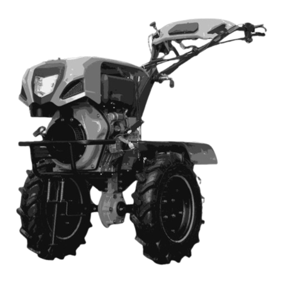
- Page 1 MB9005 ART NO: 033288 WWW.NAKAYAMATOOLS.COM...
- Page 2 Οδηγίες ασφαλείας Η ασφάλεια είναι πολύ σημαντική για εκείνον που λειτουργεί το μηχάνημα όπως επίσης και για τα άτομα που μπορεί να βρίσκονται στο περιβάλλοντα χώρο. Διαβάστε προσεκτικά τις παρακάτω οδηγίες χρήσης και ασφάλειας πριν να χρησιμοποιήσετε το μηχάνημα. Δώστε ιδιαίτερη σημασία στους παρακάτω συμβολισμούς.
- Page 3 1. Λαβή 2.Προστατευτικό κάλυμμα 3.Κιβώτιο ταχυτήτων 4.Προφυλακτήρας 5.Ρυθμιστής βάθους 6.Αξονάς ρυθμιστή βάθους 7.Αξονάς περιστροφής 8.Μαχαίρια 9.Σασμάν 10.Κινητήρας Γενικές λειτουργίες σκαπτικού 1. Τα μαχαίρια τοποθετούνται στις δύο πλευρές του κινητήριου άξονα του σκαπτικού. Σιγουρευτείτε ότι έχετε σφίξει καλά τον άξονα άλλα και τα μαχαίρια με τις κατάλληλες βίδες. Το σκαπτικό είναι τώρα έτοιμο για χρήση. Μαχαίρια...
- Page 4 Λειτουργίες και χρήσεις σκαπτικού Συναρμολόγηση 1. Κρατήστε το σώμα του σκαπτικού οριζόντια και τοποθετήστε τους κινητήριους τροχούς, στον εξάγωνο άξονα του μηχανήματος, προσέχοντας τις οπές του άξονα να είναι στην ίδια πλευρά του εξαγώνου, με τις οπές του άξονα του κινητήριου τροχού. Στην συνέχεια τοποθετήστε τους κοχλίες Μ8 Χ 55 στις οπές και με τα περικόχλια Μ8 κάντε...
- Page 5 Σιγουρευτείτε ότι έχετε παρεμβάλει την φλάντζα ανάμεσα σε κεφαλή και σωλήνα εισαγωγής. Τοποθετούμε την φλάντζα της εικόνας για στεγανοποίηση μεταξύ του φίλτρου αέρος και του σωλήνα εισαγωγής. Εικόνα 3 Γεμίζουμε το κάτω μέρος του φίλτρου αέρος με λάδι με την τρύπα που φαίνεται στην φωτογραφία. - Χρησιμοποιούμε...
- Page 6 5. Τοποθέτηση μπαταρίας ΕΞΑΡΤΗΜΑΤΑ ΤΟΠΟΘΕΤΗΣΕΙΣ ΜΠΑΤΑΡΙΑΣ Α) Μαύρο ελαστικό πέλμα 70mmx140mm B) Βίδες Μ6x125mm (2τεμαχια) με παξιμάδια Γ) Βάση συγκράτησης μπαταρίας Τοποθετούμε το ελαστικό πέλμα στην θήκη της μπαταρίας και έπειτα την μπαταρία . Πάνω από την μπαταρία τοποθετούμε την βάση (Γ) και σφίγγουμε με τις βίδες (Β). Βλέπετε την τελική εικόνα της μπαταρίας μονταρισμένη.
- Page 7 Εικόνα 9 Καλώδια μίζας 1. Μπλε στο βαρελάκι της μίζας 2. Κίτρινο στο (+) της μίζας 3. Κόκκινο στο φις του ανορθωτή Εικόνα 10 Θετικός και αρνητικός μπαταρίας α) Τοποθετούμε το (-) στην μπαταρία και την άλλη άκρη του την τοποθετείτε στην βίδα του καπακιού βαλβίδων Εικόνα...
- Page 8 7. Τοποθέτηση φτερών : τοποθετήστε πρώτα τα πλαίσια στήριξης των προφυλακτήρων στο σκαπτικό μηχάνημα. Οι δύο μικρές βάσεις τοποθετούνται στο εμπρόσθιο μέρος του σώματος του σκαπτικού, εκεί που στηρίζεται ο κινητήρας. Η μια και μεγαλύτερη βάση τοποθετείται στο οπίσθιο μέρος του σκαπτικού, επάνω από τον αυλακωτήρα.
- Page 9 Ξεβιδώστε το ρεγουλατόρο του συμπλέκτη, μέχρι ο τζόγος της ντίζας να περιοριστεί σε λιγότερο από δύο χιλιοστά και στην συνέχεια σφίξτε το περικόχλιο. 2. Ντίζα οπισθοπορείας : Χαλαρώστε το περικόχλιο που βρίσκεται στην βίδα ρεγουλατόρο. Βιδώστε την βίδα ρεγουλατόρο μέχρι το τέλος της περιστροφής της. ...
- Page 10 4. Τοποθέτηση καυσίμων: Σας προτείνουμε την χρήση λαδιού τύπου SAE20-50 ή SAE 30 για κινητήρες πετρελαίου. Τοποθετήστε την μηχανή σε επίπεδη επιφάνεια, και τοποθετήστε το λάδι στην οπή του κινητήρα. (τάπα (1) στην φωτογραφία). Η ποσότητα πρέπει να 1750ml. Ελέγξτε...
- Page 11 Επιλέξτε το λάδι της μηχανής ανάλογα με το περιβάλλον και την θερμοκρασία. Προσοχή! Το επίπεδο του λαδιού θα πρέπει να είναι πάντα στο ανώτατο όριο. Εκκίνηση (Προσοχή! Η λαβή των ταχυτήτων θα πρέπει να είναι στην θέση νεκρά) 1. Ξεκινήστε τον κινητήρα...
- Page 12 Όταν είναι ανάγκη να σταματήσετε την εργασία θα πρέπει να ακολουθείτε τις οδηγίες παύσης του κινητήρα. Σύνδεση με εξαρτήματα 1. Όταν θέλετε να πραγματοποιήσετε κάποια εκσκαφή αφαιρέστε τις ρόδες και τοποθετήστε τα μαχαίρια πάνω στον άξονα. Προσέξτε ότι έχετε τοποθετήσει σωστά τα μαχαίρι και από τις δύο μεριές του άξονα. Αφού τοποθετήσετε...
- Page 13 σκαπτικού σας θα πρέπει να γίνονται συχνά έλεγχοι των μερών του σκαπτικού και να πραγματοποιείται η σωστή διατήρηση του μηχανήματος. Έτσι το σκαπτικό θα έχει καλύτερη λειτουργία και μεγαλύτερο χρόνο ζωής. Όταν ένα σκαπτικό είναι καινούριο ή έχει δεχτεί μεγάλη επισκευή δεν θα πρέπει να δουλεύει για παραπάνω από μία...
- Page 14 Καθαρίστε βρωμιές και λάσπες Ελέγξτε για ελαττώματα Ρυθμίστε τα λειτουργικά μέρη Δίσκος συμπλέκτη Ταχύτητες και άλλα μέρη Αποθήκευση του σκαπτικού για μεγάλη χρονική περίοδο Όταν θέλετε να αποθηκεύσετε το σκαπτικό για μεγάλο χρονικό διάστημα ακολουθήστε τα παρακάτω βήματα: 1. Καθαρίστε καλά το σκαπτικό από σκόνες και λάδια. 2.
- Page 15 Φαινόμενο Αιτία Λύση Η μέγιστη, ελάχιστη και η νεκρά Οι βίδες πίσω από τον άξονα θα είναι Σφίξτε τις βίδες και τα παξιμάδια ταχύτητα δεν κουμπώνουν χαλαρές Το συνεμπλόκ είναι φθαρμένο change auxiliary brick Το ελατήριο στο κεντρικό άξονα είναι Αλλάξτε...
- Page 16 Προβλήματα στην τροφοδοσία Φαινόμενο Αιτία Λύση Η τροφοδοσία κάνει υπερβολικό Έχει μεγάλο φορτίο ή δεν έχει Ρυθμίστε την τροφοδοσία ξανά θόρυβο επισκευαστεί σωστά Η ντίζα της τροφοδοσίας έχει Η εγκατάσταση της τροφοδοσίας δεν Κάντε ξανά την εγκατάσταση μεγάλα κενά έχει γίνει σωστά Δεν...
- Page 17 Precautions When starting the machine, set shifting bar to the neutral position. When the machine is working, pay attention to the safety! Be careful not to be hurt by the rotary blades! When grasp the reverse handle, the shifting bar must be set to the neutral position. ...
- Page 18 II. General View 1. Handle Bar 10. Bumper 2. Gear-box Assy. 11. Throttle Switch 3. Adjustment Screw 12. Battery base 4. Fender 13. Safety Device ( Dead-man Handle) 5. Deep Furrowing Resistance Stick 14. Locked handle (up & low) 6. Rotary Blade 15.
- Page 19 Chapter Two Main Applications of Power tiller Ⅰ. Cultivating Fix the cultivating device onto the left and right side of the transmission shaft of the running part of the power tiller, then use two M8×55 screw bolts for axial positioning. After that, the machine can start cultivating finally.
- Page 20 Chapter Three Operation & Use Method of Power tiller Ⅰ. Assembly After Unpacking (see Figure 4) Figure 1. Fix the main machine, insert the hexagonal output shaft into stepped box’s output casing’s hexagonal hole. 2.Fix the hexagonal stop casing onto the hexagonal output shaft with M6×6 socket head screws, and make the hexagonal shaft not move axially.
- Page 21 handle bar support base, and insert it into the hole of the shift casing, then fix it with split pin 3.2 ×16. ¢ set the shifting bar in neutral position. 7. Assembly drawing of safety protection guard install. 1. BRACKET OF COLLISION BUMPER(LEFT) 2.
- Page 22 After maintenance the safety protection guard installment must fix it on the power ATTENTION: tiller wholly Ⅱ. Installation and Adjustment for cable 1. Adjustment of the clutch cable. (See Figure 5 and 6) ① Unscrew the locknut of the tie rod ②...
- Page 23 the fork arm of the clutch, and put the joint of cable into the wire socket. ⑤ Unscrew the tie rod, grasp and loosen the clutch handle until the spring force in the clutch can reset the handle, then screw the locknut. 2.
- Page 24 Ⅲ Check and Refueling 1. Check whether all the connection bolts are loose or not, and fix the connection bolts according to the moment of force listed in table 3. (Refer to the instruction manual for diesel engine for the screwing moment of force bolt and nut respectively) Name of parts Moment of force (N.M)
- Page 25 engine oil into the air cleaner. Select the appropriate lubricant for the diesel engine according to the ② environmental temperature. (See figure 9) 4. Refill 0# or -10# or -20# light diesel into the diesel engine.(See the instruction manual of the diesel engine for details) Note: do not exceed the mark when refilling.
- Page 26 the fast shift position, and observe whether it reaches the right position or not. Then the right hand grasps the right handle. (Note: do not grasp the reversing bar) ③ Loosen the clutch handle gradually, the clutch will combine, and the power tiller can run at a fast speed.
- Page 27 ④ Fasten upon the handle bar(Grasp the emergency stop handle and the handle bar with your left hand), and buckle the trigger of emergency stop lock come out from the clutch handle gently by your middle finger, the clutch handle restoration adown, then the clutch switch on, and the machine start to work.
- Page 28 Width scope of ditching : 14cm-40cm Depth scope of ditching: 11cm-25cm 4. Short distance transport Fix forearm of the wagon box on the trailer and wheels on the transmission shaft of the running part, the machine can do a transportation job. The rated load is 250kg, under normal rotated speed of the diesel engine, speed of the fast shift is about 10 km/h and that of the slow shift is about 5km/h.
- Page 29 occuring to other people or their property. Ⅷ. Preparation 1. The safety protection guard must be attached to the machine before using. 2. Check that the blade and fender are correctly assend and securely fastened. 3. While working, always wear substantial footwear and long trousers. Do not operate the equipment when barefoot or wearing open sandals.
- Page 30 away from the tool(s). 10. Do not put hands or feet near or under rotating parts. 11. Never pick up or carry a machine while the engine is running 12. Stop the engine ----whenever you leave the machine ----before refueling 13.
- Page 31 2. When the power tiller is working, keep an eye on the rotary parts, do not be too close to the machine to avoid being hurt by the rotary blades. 3. Keep the components of oil box away from fire and smoke. 4 .
- Page 32 6. Please pay attention to warning signs Chapter Four Maintenance & Service Method of power tiller During the working period of the power tiller, due to the change of running, abrasion and loading, phenomena of bolts loosening and parts wearing are inevitable, these phenomena lead to the malfunction of the system, abnormalities of clearances, declination of engine power, more oil consumption, malfunction of each part, more failures of the machine, and the problems affect the normal use of the power tiller.
- Page 33 4. To reduce the fire hazard, keep the engine, muffler, battery compartment and diesel storage area free of vegetative material and excessive grease. 5. Replace worn or damaged parts for safety. 6. If the fuel tank has to be drained, this shall be done outdoors 7.
- Page 34 Ⅳ Technical Service List of Power tiller (The mark O means the required service) Work Interval Every hours The 1 month The 3 month or Every year or Every two years Items to service under half after after 150 hours after 1000 after...
- Page 35 Chapter Five Debugging Method of Power tiller Ⅰ. Debugging Method of Mesh of Bevel Gear When the abnormal transmission of mesh of bevel gear of sound is confirmed, stop the machine and check as stipulated below: 1. Clearance adjustment of mesh of angel gear in gear-box ( See Figure 10) ①...
- Page 36 piece of the clutch can be confirmed. The machine should be sent to special service centre for replacing with a new fork of friction piece of the clutch. 3. Dismount the clutch by unspecialized person, which may cause damage to the clutch and the machine is forbidden.
- Page 37 Chapter Six Troubleshooting of Power Tiller Ⅰ. Troubleshooting of Diesel Engine. Refer to the instruction manual of diesel engine. Ⅱ. Troubleshooting of Clutch (Note: do not dismount the clutch assembly by yourself. Contact our company or our dealers to shoot the troubles marked with ※ Symptom Cause Terms of settlement...
- Page 38 position Driving angle gear is loose Tighten the round nuts Excess abrasion of the upper hole in the Replace the support arm assembly connection piece of support arm Positioning spring inside the main shaft does Replace not function Main shaft is moving ,the bolts for tightening Screw the bolts tight the cover for the rear of the gear-box body are loose...
- Page 39 Oil leakage of the fork shaft Malfunction of O-shaped ring Replace with O-shaped ring ∮1.2×1.8 of the clutch Malfunction of O-shaped ring Oil leakage of the shift shaft Replace with O-shaped ring ∮1.2×1.8 The bolts are loose there Screw the bolts tight Oil leakage of the flange connection The vulcanized paper board is damaged there Replace...
- Page 40 Ⅴ Other Troubleshooting Symptom Cause Terms of settlement The cultivating blade is Collide with the hard things Replace it. Avoid colliding with broken like stones when working hard things like stones in the earth when working The manipulation cable Long-time abrasion in work Replace is broken Closing...
Need help?
Do you have a question about the MB9005 and is the answer not in the manual?
Questions and answers