
Subscribe to Our Youtube Channel
Related Manuals for Nakayama MB6000


Summary of Contents for Nakayama MB6000
- Page 1 MB6000 | Σκαπτικό Μετάφραση του πρωτοτύπου των Owner’s manual οδηγιών χρήσης Art Nr: 000495 AKAYAMA OOLS...
- Page 2 ΠΕΡΙΕΧΟΜΕΝΑ 1. Πρόλογος 2. Οδηγίες ασφάλειας 3. Σύμβολα 4. Μέρη του εργαλείου 5. Συναρμολόγηση 6. Έλεγχος προ λειτουργίας 7. Προετοιμασία λειτουργίας 8. Εκκίνηση μηχανής 9. Λειτουργία 10. Παύση μηχανής 11. Διατήρηση 12. Μεταφορά/ αποθήκευση 13. Προβλήματα Χαρακτηριστικά AKAYAMA OOLS...
- Page 3 1. Πρόλογος Αυτό το μηχάνημα είναι κατάλληλο για σκάβει ελαφρύ χώμα, να δημιουργεί βαθουλώματα ποτίσματος με βάθος μέχρι 10% και σε υγρό έδαφος όπου το βάθος του νερού δεν θα πρέπει να είναι μεγαλύτερο από 250mm. Εάν θέλετε να χρησιμοποιήσετε το μηχάνημα σε σημείο όπου υπάρχουν χόρτα θα πρέπει να καθαρίσετε...
- Page 4 Κρατήστε όλες της βίδες και τα παξιμάδια σφιχτά για να εξασφαλίσετε την καλύτερη και ασφαλέστερη λειτουργία του εργαλείου. ii) Μην αποθηκεύσετε ποτέ το εργαλείο με καύσιμα μέσα στην δεξαμενή. iii) Αφήστε το μηχάνημα να κρυώσει καλά πριν το αποθηκεύσετε κάπου. iv) Για...
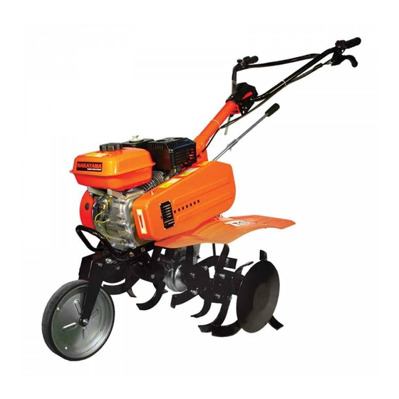
- Page 5 (1) Αριθμός πλαισίου (2) Δεξαμενή καυσίμου (3) Τάπα λαδιού (4) Προφυλακτήρας (5) Ρόδα (6) Ρυθμιστής βάθους (7) Άξονας σύνδεσης (8) Λαβή (9) Διακόπτης ταχύτητας (10) Ρυθμιστής ύψους λαβής (11) Άξονας ασφάλειας (12) Διακόπτης μηχανής (13) Συμπλέκτης (14) Μοχλός ταχυτήτων (15) Προστατευτικό κάλυμμα λουριού (16) Μαχαίρια...
- Page 6 Αφαιρέστε όλα τα τεμάχια από το κουτί και αφαιρέστε μετά την πλαστική σακούλα και το μηχάνημα είναι έτοιμο για συναρμολόγηση. Κάθε ένα από τους παρακάτω αριθμούς αντιστοιχεί με την ανάλογη εικόνα που βρίσκεται παρακάτω. 1) Εγκαταστήστε τις ρόδες για να κρατηθεί το σώμα του εργαλείου. 2) Συναρμολογήστε...
- Page 7 AKAYAMA OOLS...
- Page 8 AKAYAMA OOLS...
- Page 9 AKAYAMA OOLS...
- Page 10 AKAYAMA OOLS...
- Page 11 AKAYAMA OOLS...
- Page 12 AKAYAMA OOLS...
- Page 13 AKAYAMA OOLS...
- Page 14 6. Έλεγχος προ λειτουργίας Προσοχή! Μην ξεκινήσετε ποτέ την μηχανή πριν να ολοκληρώσετε όλα τα παραπάνω βήματα συναρμολόγησης. Κάποια μηχανήματα παραδίδονται χωρίς λάδια στην μηχανή. Γεμίστε λάδια στην μηχανή πριν να χρησιμοποιήσετε το εργαλείο. 6.1 Τοποθέτηση λάδι μηχανής 6.1.1 Τοποθετήστε το εργαλείο σε επίπεδη επιφάνεια. 6.1.2 Χαλαρώστε...
- Page 15 6.1.3 Προτείνουμε να χρησιμοποιήσετε λάδι τύπου SAE20-50 για βενζινοκινητήρες. 6.1 Τοποθέτηση λάδι ταχυτήτων Τοποθετήστε το μηχάνημα σε μια επίπεδη επιφάνεια και αφαιρέστε την τάπα. Το επίπεδο του λαδιού θα πρέπει να είναι στο ίδιο επίπεδο με την κάτω εσοχή της τρύπας γεμίσματος λαδιού.
- Page 16 (1) Χάρτινο στοιχείο (2) Στοιχείο αφρολέξ 7. Προετοιμασία λειτουργίας 7.1 Ρυθμιστής ύψους λαβής Προσοχή! Πριν να ρυθμίσετε την λαβή τοποθετήστε το μηχάνημα σε μία επίπεδη επιφάνεια για να αποφύγετε την κατά λάθος διάλυση ης λαβής. Για να ρυθμίσετε το ύψος της λαβής, χαλαρώστε...
- Page 17 8.2 Κλείστε το μοχλό του τσοκ Σημείωση: Μην χρησιμοποιήσετε το μοχλό του τσοκ εάν η μηχανή είναι ζεστή ή εάν η θερμοκρασία του αέρα είναι υψηλή. (1) Μοχλός τσοκ (2) Κλειστή θέση 8.3 Γυρίστε το διακόπτη της μηχανής στην θέση On (1) Θέση...
- Page 18 Το μηχάνημα μπορεί να αλλάξει από την προς τα μπροστά λειτουργία ( θέση F) στην λειτουργία όπισθεν (θέση R). (N) είναι η θέση νεκρά. Γυρίστε το διακόπτη ταχύτητας στην χαμηλή ταχύτητα. Απελευθερώστε το μοχλό του συμπλέκτη για να απενεργοποιήσετε τον ...
- Page 19 4. Γυρίστε την βαλβίδα καυσίμου στη θέση Off. (1) Βαλβίδα καυσίμου (2) Θέση Off 11. Διατήρηση Ο σκοπός του σχεδιαγράμματος διατήρησης είναι να κρατήσει το μηχάνημα στην καλύτερη δυνατόν κατάσταση. Ελέγξτε ή πραγματοποιήστε σέρβις όπως αναγράφετε παρακάτω. Περίοδος πραγματοποίησης σέρβις. Πραγματοποιήστε...
- Page 20 Να πλύνετε τα χέρια σας με άφθονο σαπούνι και νερό όταν έχετε έρθει σε επαφή με λάδι. Σημείωση: Παρακαλώ πετάξτε το χρησιμοποιημένο λάδι μηχανής με τρόπο φιλικό προς το περιβάλλον. Μην το πετάξετε στα σκουπίδια και μην το χύσετε στο έδαφος αλλά μεταφέρετέ το μέσα...
- Page 21 11.6 Ρύθμιση καλωδίου ταχύτητας Μετρήστε το κενό που υπάρχει στο μοχλό. Κενό: 5-10mm Εάν το κενό είναι λάθος, χαλαρώστε το παξιμάδι και γυρίστε το παξιμάδι ρύθμισης προς τα μέσα ή προς τα έξω ανάλογα με το τι χρειάζεται. (1) Μοχλός ταχύτητας (2) Παξιμάδι...
- Page 22 Εάν όλα είναι εντάξει προσπαθήστε να ξεκινήσετε ξανά το μηχάνημα ακολουθώντας τις οδηγίες. Εάν και πάλι δεν ξεκινά στείλτε το μηχάνημα για σέρβις σε εξουσιοδοτημένο τεχνικό προσωπικό ή πίσω στο προμηθευτή σας. Ποσότητα Είδος MB6000 Διαστάσεις (Μ*Π*Υ) 1380*650*970 Βάρος(kg) 45/60 Σύστημα...
- Page 23 FORWORD Thank you for purchasing a tiller. This manual covers operation and maintenance of the tiller. All information in this publication is based on the latest product, information available at the time of approval for printing. We reserves the right to make changes at any time without notice and without incurring any obligation. This manual should be considered a permanent part of the tiller and remain with it if it is resold.
- Page 24 WARNING 1) Training a) read the instructions carefully. Be familiar with the controls and the proper use of the equipment; b) never allow children or people unfamiliar with these instructions to use the machine. Local regulations can restrict the age of the operator; c) never work while people, especially children, or pets are nearby;...
- Page 25 SAFETY LABEL LOCATIONS These labels warn you of potential hazards that can cause serious injury. Read the labels and safety notes and precautions described in this manual carefully. If a label comes off or becomes hard to read, contact your dealer for a replacement. APPLICABLE SCOPE The micro-tiller is suitable for cultivating the sandy soil and clayey soil of canopied vegetables base and dry land, slopes with gradient less than 10%, paddy field with the depth of water surface to hard...
- Page 26 (1) frame serial number (2)fuel tank (3)transmission oil filler cap (4) mud fender (5) wheel (6) drag bar (7) connecting bar (8) handle bar (9) throttle control (10) handle height adjuster (11) safety bar (12) engine switch (13)clutch (14) shift level (15) belt cover (16) blade PRE-OPERATION CHECK...
- Page 27 3.AIR CLEANER Check cleaner for dirt or obstruction of elements (1) elements 4.FUEL Use automotive gasoline (Unleaded or lowleaded is preferred to minimize combustion chamber deposits.) Never use an oil/gasoline mixture or dirty gasoline. Avoid getting dirt, dust or water in the fuel tank. CAUTION: Do not fill over the red level line.
- Page 28 NOTE: ·Fuel system damage or engine performance problems resulting from the use of fuels that contain alcohol is not covered under the warranty. The tiller can not endorse the use of fuels containing methanol since evidence of their suitability is as yet in complete. ·Before buying fuel from an unfamiliar station, try to find out if the fuel contains alcohol, if it does confirm the type and percentage of alcohol used.
- Page 29 3. Turn the engine switch to ON. (1) ON (2) ENGINE SWITCH 4. Move the throttle lever slightly to the right. (1) THROTTLE LEVER 5. Pull the starter grip lightly until resistance is felt then pull briskly. CAUTION: Do not allow the starter grip to snap back against the engine. Return it gently to prevent damage to the starter.
- Page 30 TILLER OPERATION 1. Handlebar height adjustment CANTION: Before adjusting the handlebar, place the tiller on firm level ground to prevent the handle from collapsing accidentally. To adjust the handlebar height, loosen the adjuster, select the appropriateplace and tighten the adjuster. (1) ADJUSTER 2.
- Page 31 Gear shifting : ·Return the throttle lever to the extreme right. ·Release the clutch lever to disengage the clutch. ·Move the shift lever to the desired gear position., NOTE: If the shift lever will not engage the desired gear, squeeze the clutch lever and move the tiller slightly to reposition the gears.
- Page 32 8. Handling Tips Adjust the handlebar height to a comfortable position (waist height for normal tilling) Should the machine jerk forward while tilling, press down the handlebars, if the machine will not move forward, move the handlebars from side to side. Turn: The proper method of negotiating a turn during a tilling operation is to lower the handlebars to bring the gravity centre toward the rear and then make the turn.
- Page 33 STOPPING THE ENGINE In an emergency Turn the engine switch to OFF. (1) OFF (2) ENGINE SWITCH In normal use ·Release the clutch lever to DISENGAGED position and shift lever is in neutral position. (1) CLUTCH LEVER (2) DISENGGAGED 1. Move the throttle lever fully to the right. (1) THROTTLE LEVER 2.
- Page 34 MAINTENANCE The purpose of the maintenance schedule is to keep the tiller in the best operating condition, inspect or service as scheduled in the table below. WARNING Shut off the engine before performing any maintenance. If the engine must be run, make sure the area is good ventilated.
- Page 35 Wash your hands with soap and water after handling used oil. NOTE: Please dispose of used motor oil in a manner that is compatible with the environment. We suggest you take it in a sealed container to your local service for reclamation. Do not throw it in the trash or pour it on the ground.
- Page 36 removed parts in solvent, dry them thoroughly and reinstall them securely. Turn the fuel valve ON and check for leaks. (1) O-RING (2) FUEL STRAINER CUP 4. Spark plug service Recommended spark plug: BPR5ES (NGK) W16EPR-U (NIPPONDENSO) To ensure proper engine operation, the spark plug must be properly gapped and free of deposits. ·Remove the spark plug cap.
- Page 37 ·Tighten a new spark plug 1/2 turn with the wrench to compress the washer if you are reuse a plug, it should only take 1/4-1/2 turn after the plug seats. CAUTION: The spark plug must be securely tightened. An improperly tightened plug can become very hot and possibly damage the engine.
- Page 38 the outside face of the driven pulley by using a straight gauge. (1) ENGINE MOUNTING BOLTS (2) ENGINE STAY TIGHTENING BOLE Loosen the belt stopper attaching bolts. Adjust the clearance between the belt stopper and the belt as illustrated with the clutch lever squeezed.
- Page 39 4. Change engine oil. 5. Cover tiller with plastic sheet. Do not place the tiller with the handlebars on the ground. It will cause the oil entering the cylinder or the fuel spillage. TROUBLESHOOTING When the engine will not start: ·Is there enough fuel? ·Is the fuel valve on? ·Is the engine switch ON?
- Page 40 SPECIFICATIONS MB6000 ITEM Dimension (L*W*H) 1380*800*1070 N.W/G.W(kg) Transmission system Belt TILLER Tilling scope(mm) 900-1080 Tilling depth(mm) 150-250 FORWARD NEUTRAL REVERSE Gear shifting SWIFT NEUTRAL TARDY Model 168FB/A(GX160) Type 1-cylindor, 4stroke,OHV25, forced air cooled φ68*54 Bore*stroke(mm) Displacement(ml) Compression ratio 8.5:1 Max. power (kw/rpm) 3.8/3600...
- Page 41 AKAYAMA OOLS...
Need help?
Do you have a question about the MB6000 and is the answer not in the manual?
Questions and answers