Endress+Hauser Dosimag Operating Instructions Manual
Electromagnetic flowmeter
Hide thumbs
Also See for Dosimag:
- Operating instructions manual (84 pages) ,
- Brief operating instructions (40 pages) ,
- Operating instructions manual (76 pages)
Table of Contents
Advertisement
Quick Links
KA01175D/06/EN/01.14
71255175
Products
Brief Operating Instructions
Dosimag
Electromagnetic flowmeter
These Instructions are Brief Operating Instructions; they are
not a substitute for the Operating Instructions pertaining to
the device.
Detailed information about the device can be found in the
Operating Instructions and the other documentation:
• On the CD-ROM supplied (is not included in the delivery for
all device versions).
• Available for all device versions via:
– Internet:
www.endress.com/deviceviewer
– Smart phone/tablet: Endress+Hauser Operations App
Description of the procedure (→ 9)
Solutions
Services
Advertisement
Table of Contents

Related Manuals for Endress+Hauser Dosimag


Summary of Contents for Endress+Hauser Dosimag
- Page 1 Operating Instructions and the other documentation: • On the CD-ROM supplied (is not included in the delivery for all device versions). • Available for all device versions via: – Internet: www.endress.com/deviceviewer – Smart phone/tablet: Endress+Hauser Operations App Description of the procedure (→ 9)
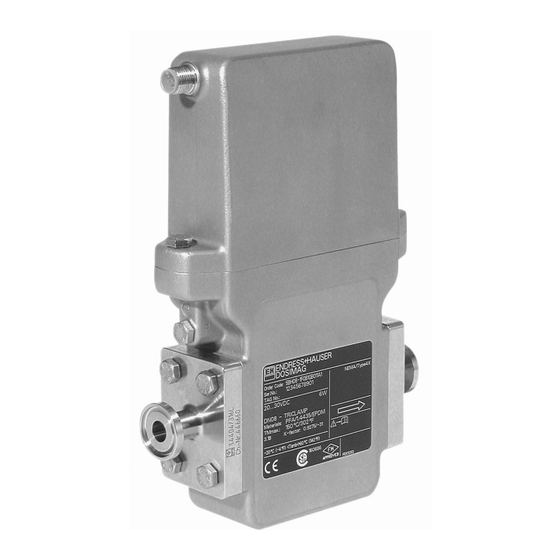
- Page 2 Dosimag Order code 00X00-XXXX0XX0XXX Ser. No.: X000X000000 TAG No.: XXX000 Serial number www.endress.com/deviceviewer Endress+Hauser Operations App A0023555 Endress+Hauser...
-
Page 3: Table Of Contents
Dosimag Table of contents Table of contents Document information ............4 Symbols used . -
Page 4: Document Information
Document information Dosimag Document information Symbols used 1.1.1 Safety symbols Symbol Meaning DANGER! DANGER This symbol alerts you to a dangerous situation. Failure to avoid this situation will result in serious or fatal injury. WARNING! This symbol alerts you to a dangerous situation. Failure to avoid this situation can result in WARNING serious or fatal injury. - Page 5 Dosimag Document information 1.1.3 Symbols for certain types of information Symbol Meaning Permitted Indicates procedures, processes or actions that are permitted. Preferred Indicates procedures, processes or actions that are preferred. Forbidden Indicates procedures, processes or actions that are forbidden. Indicates additional information.
-
Page 6: Basic Safety Instructions
Verification for borderline cases: ‣ For special fluids and fluids for cleaning, Endress+Hauser is glad to provide assistance in verifying the corrosion resistance of fluid-wetted materials, but does not accept any warranty or liability as minute changes in the temperature, concentration or level of contamination in the process can alter the corrosion resistance properties. -
Page 7: Workplace Safety
It meets general safety standards and legal requirements. It also complies with the EC directives listed in the device-specific EC Declaration of Conformity. Endress+Hauser confirms this by affixing the CE mark to the device. IT security We only provide a warranty if the device is installed and used as described in the Operating Instructions. -
Page 8: Incoming Acceptance And Product Identification
(depends on device version) and documents present? • If one of the conditions is not satisfied, contact your Endress+Hauser Sales Center. • Depending on the device version, the CD-ROM might not be part of the delivery! In such cases, the technical documentation is available via the Internet or via the Endress +Hauser Operations App, see the "Device documentation"... -
Page 9: Product Identification
• Enter serial numbers from nameplates in W@M Device Viewer (www.endress.com/deviceviewer): All information about the measuring device is displayed. • Enter the serial number from the nameplates into the Endress+Hauser Operations App or scan the 2-D matrix code (QR code) on the nameplate with the Endress+Hauser Operations App: all the information for the measuring device is displayed. -
Page 10: Storage And Transport
Enter the serial number (Ser. no.) of the device: see nameplate (→ 1, 9). All the associated documentation is displayed. Endress+Hauser Operations App The Endress+Hauser Operations App is available for Android (Google play) and iOS (App Store). Via the serial number: Launch the Endress+Hauser Operations App. - Page 11 Dosimag Storage and transport A0015604 Do not remove protective covers or caps installed on process connections. They prevent mechanical damage to the sealing surfaces and contamination in the measuring tube. 4.2.1 Measuring devices without lifting lugs WARNING Center of gravity of the measuring device is higher than the suspension points of the webbing slings.
- Page 12 Storage and transport Dosimag CAUTION Risk of damaging the magnetic coil ‣ If transporting by forklift, do not lift the sensor by the metal casing. ‣ This would buckle the casing and damage the internal magnetic coils. A0023726 Endress+Hauser...
-
Page 13: Installation
Dosimag Installation Installation Installation conditions 5.1.1 Mounting position Mounting location A0023343 h ≥ 2 × DN Installation in down pipes Install a siphon with a vent valve downstream of the sensor in down pipes whose length h ≥ 5 m (16.4 ft). This precaution is to avoid low pressure and the consequent risk of damage to the measuring tube. - Page 14 Installation Dosimag Installation in partially filled pipes A partially filled pipe with a gradient necessitates a drain-type configuration. A0017063 Orientation The direction of the arrow on the sensor nameplate helps you to install the sensor according to the flow direction.
- Page 15 Dosimag Installation A0003829 4 Horizontal installation Measuring electrodes Liner In the event of extreme heating (e.g. for CIP or SIP cleaning processes), we recommend you install the measuring device in such a way that the transmitter part is pointing downwards.
- Page 16 Installation Dosimag For the dimensions and installation lengths of the device, see the "Technical Information" document, "Mechanical construction" section 5.1.2 Requirements from environment and process Ambient temperature range For detailed information on the ambient temperature range, see the Operating Instructions for the device (→ 9)
- Page 17 Dosimag Installation Vibrations A0016266 6 Measures to avoid device vibrations (L > 10 m (33 ft)) Adapters [mbar] 8 m/s 7 m/s 6 m/s 5 m/s 4 m/s max. 8° 3 m/s 2 m/s 1 m/s d / D...
-
Page 18: Mounting The Measuring Device
Installation Dosimag Mounting the measuring device WARNING Danger due to improper process sealing! ‣ Ensure that the inside diameters of the gaskets are greater than or equal to that of the process connections and piping. ‣ Ensure that the gaskets are clean and undamaged. -
Page 19: Post-Installation Check
Dosimag Installation • The screws must be firmly tightened. The process connection forms a metal connection with the sensor, which ensures a defined compression of the seal. • Depending on the application the seals should be replaced periodically, particularly if... -
Page 20: Electrical Connection
Electrical connection Dosimag Electrical connection Connection conditions WARNING Risk of electric shock. ‣ Have electrical connection work carried out by correspondingly trained specialists only. ‣ Observe applicable federal/national installation codes and regulations. ‣ Comply with local workplace safety regulations. ‣... - Page 21 Dosimag Electrical connection 6.2.1 Pin and socket assignment Pulse/frequency/status output (option 3) A0023685 7 Connection (option 3) Option 3: Pulse/frequency/status output Assignment RSE8 M12 × 1 L+ Supply voltage: 24 V nominal voltage (20 to 30 V ), 4.5 W...
- Page 22 Electrical connection Dosimag Modbus RS485/batching option (option 4 and 5) A0023687 8 Connections for Modbus RS485/batching option (option 4 and 5) Option 4 and 5: Modbus RS485/batching option Assignment RSE8 M12 × 1 Supply voltage: 24 V nominal voltage (20 to 30 V ), 4.5 W (+500 mA per batch...
- Page 23 Dosimag Electrical connection Coding Plug/socket C: Socket D: Plug Option 5: Modbus RS485/2 batch outputs RSE5 M12 × 1 Assignment Batch output 2 – Batch / AUX Batch output 1 N.C. Coding Plug/socket C: Socket D: Plug 6.2.2 Electrical connection M12 socket ×...
- Page 24 Electrical connection Dosimag Connection option 3 A0023237 9 8-pin device connection Socket, input Connector, input Supply voltage + Service interface Service interface Supply voltage – (+) pulse/frequency/status output (–) pulse/frequency/status output (–) pulse/frequency/status output Service interface PELV or SELV power supply...
- Page 25 Dosimag Electrical connection Connection option 4 A0023238 10 Batch option with 1 valve Socket, input Connector, input B.1 Supply voltage + B.2 Service interface B.3 Service interface B.4 Supply voltage – B.5 N.C. B.6 Modbus A B.7 Modbus B B.8 Service interface...
- Page 26 Electrical connection Dosimag Connection option 5 A0023239 11 Batch option with 2 valves Socket, input Connector, input B.1 Supply voltage + B.2 Service interface B.3 Service interface B.4 Supply voltage – B.5 N.C. B.6 Modbus A B.7 Modbus B B.8 Service interface...
-
Page 27: Ensuring The Degree Of Protection
Dosimag Electrical connection Ground connection The ground connection is via a cable lug that must be mechanically connected to the ground connection of the measuring device. A0003838 12 Ground connection 6.2.3 Cable specifications Use connecting cables with a cross-section of at least 0.25 mm (0.0004 in... -
Page 28: Post-Connection Check
Customer-specific configuration with DeviceCare and FieldCare The device is operated via the DeviceCare and FieldCare operating programs. DeviceCare and FieldCare are universal service and configuration programs from Endress+Hauser. Connection is by means of the service adapter with an FXA291 service interface. -
Page 29: System Integration
• DVD (contact Endress+Hauser) To ensure the correct operation of the DeviceCare and FieldCare programs, the computer running the programs must meet certain minimum requirements with regard to hardware and software. The minimum requirements are listed on the Endress+Hauser website www.endress.com. System integration For information on system integration, see the Operating Instructions for the device (→... -
Page 30: Commissioning
Commissioning Dosimag Commissioning Function check Before commissioning the device, make sure that the post-installation and post-connection checks have been performed. • "Post-installation check" checklist (→ 19) • "Post-connection check" checklist (→ 28) Switching on the measuring device If the post-installation checks have been performed successfully, switch on the supply voltage. - Page 31 Dosimag Commissioning ‣ Low flow cut off (→ 38) ‣ Advanced setup (→ 39) 9.3.1 Defining the tag name To enable fast identification of the measuring point within the system, you can enter a unique designation using the Device tag parameter and thus change the factory setting.
- Page 32 Commissioning Dosimag Parameter overview with brief description Parameter Description Selection Factory setting Volume flow unit Select volume flow unit. Unit choose list Country-specific: • 138 = l/h Result • 16 = gal/min (us) The selected unit applies for: • Output •...
- Page 33 Dosimag Commissioning Parameter overview with brief description Parameter Description User entry / Selection Factory setting Bus address Enter device address. 1 to 247 Baudrate Define data transfer speed. • 0 = 1200 BAUD 4 = 19200 BAUD • 1 = 2400 BAUD •...
- Page 34 Commissioning Dosimag 9.3.4 Configuring the status input (option 4 and 5) The Status input submenu guides you systematically through all the parameters that have to be set for configuring the input. Navigation "Setup" menu → Status input Status input Assign status input...
- Page 35 Dosimag Commissioning Parameter overview with brief description Parameter Description Selection Factory setting Batch profile Select suitable profile for • 0 = Profile 1 0 = Profile 1 fluid configured by • 1 = Profile 2 customer. • 2 = Profile 3 •...
- Page 36 Commissioning Dosimag 9.3.6 Configuring the pulse/frequency/switch output (option 3) The Pulse/frequency/switch output 1 submenu contains all the parameters that must be configured for the configuration of the selected output type. Navigation "Setup" menu → PFS output 1 to 2 Pulse/frequency/switch output 1 to 2...
- Page 37 Dosimag Commissioning Failure mode Failure frequency Switch-on value Switch-off value Failure mode Invert output signal Parameter overview with brief description Parameter Description Selection / User entry Factory setting Operating mode Define the output as a • 0 = Off 2 = Pulse pulse, frequency or switch •...
- Page 38 Commissioning Dosimag Parameter Description Selection / User entry Factory setting Value per pulse Enter measured value at Signed floating-point which a pulse is output. number Pulse width Define time width of the 0.05 to 3.75 ms 0.05 ms output pulse. Failure mode Define output behavior in •...
-
Page 39: Advanced Settings
Dosimag Commissioning Off value low flow cutoff Pressure shock suppression Parameter overview with brief description Parameter Description Selection / User entry Factory setting Assign process variable Select process variable for • 0 = Off 1 = Volume flow low flow cut off. - Page 40 Commissioning Dosimag Parameter overview with brief description Parameter Description User entry Factory setting Enter access code Enter access code to disable 0 to 9 999 write protection of parameters. 9.4.2 Sensor adjustment The Sensor adjustment submenu contains parameters that pertain to the functionality of the sensor.
-
Page 41: Simulation
Dosimag Commissioning Parameter overview with brief description Parameter Description Selection Factory setting Assign process variable Select process variable for • 0 = Off 1 = Volume flow totalizer. • 1 = Volume flow Volume unit Select volume unit. Unit choose list 2 = m³... -
Page 42: Diagnostic Information
Diagnostic information Dosimag Value process variable Simulation device alarm Simulation diagnostic event Parameter overview with brief description Parameter Prerequsite Description Selection / User Factory setting entry Assign simulation – Select a process • 0 = Off 0 = Off process variable variable for the •... - Page 44 www.addresses.endress.com...
Need help?
Do you have a question about the Dosimag and is the answer not in the manual?
Questions and answers