
Related Manuals for Endress+Hauser Dosimass IO-Link


Summary of Contents for Endress+Hauser Dosimass IO-Link
- Page 1 Products Solutions Services BA02330D/06/EN/01.24-00 71658073 2024-08-15 Valid as of version 01.00.zz (Device firmware) Operating Instructions Dosimass IO-Link Coriolis flowmeter...
- Page 2 • The manufacturer reserves the right to modify technical data without prior notice. Your Endress+Hauser sales organization will supply you with current information and updates to this manual. Endress+Hauser...
-
Page 3: Table Of Contents
Dosimass IO-Link Table of contents Table of contents 7.2.3 Available device plugs ... . 26 About this document ....5 7.2.4... - Page 4 13.2 Measuring and test equipment ... . 46 13.3 Endress+Hauser services ....46 Repair ......47 14.1 General information .
-
Page 5: About This Document
Dosimass IO-Link About this document About this document Document function These Operating Instructions contain all the information required in the various life cycle phases of the device: from product identification, incoming acceptance and storage, to installation, connection, operation and commissioning, through to troubleshooting, maintenance and disposal. -
Page 6: Symbols In Graphics
• Device Viewer (www.endress.com/deviceviewer): Enter the serial number from the nameplate • Endress+Hauser Operations app: Enter serial number from nameplate or scan matrix code on nameplate. The following documentation may be available depending on the device version ordered: Document type... -
Page 7: Registered Trademarks
Dosimass IO-Link About this document Document type Purpose and content of the document Operating Instructions (BA) Your reference document These Operating Instructions contain all the information that is required in the various life cycle phases of the device: from product identification,... -
Page 8: Safety Instructions
Safety instructions Dosimass IO-Link Safety instructions Requirements for the personnel The personnel for installation, commissioning, diagnostics and maintenance must fulfill the following requirements: ‣ Trained, qualified specialists must have a relevant qualification for this specific function and task. ‣ Are authorized by the plant owner/operator. -
Page 9: Workplace Safety
Verification for borderline cases: ‣ For special fluids and fluids for cleaning, Endress+Hauser is glad to provide assistance in verifying the corrosion resistance of fluid-wetted materials, but does not accept any warranty or liability as minute changes in the temperature, concentration or level of contamination in the process can alter the corrosion resistance properties. -
Page 10: Product Description
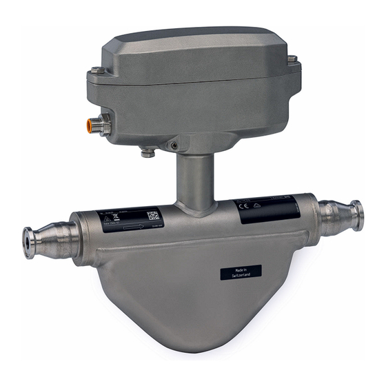
Product description Dosimass IO-Link Product description The device consists of a transmitter and a sensor. Product design A0055042 1 Important measuring instrument components DN 1 to 4 (¹⁄₂₄ to ¹⁄₈") Transmitter Sensor A0055044 2 Important measuring instrument components DN 8 to 40 (³⁄₈ to ⁄1 ½") -
Page 11: Incoming Acceptance And Product
• Enter the serial numbers from the nameplates in the Device Viewer (www.endress.com/deviceviewer): all the information about the device is displayed. • Enter the serial numbers from the nameplates into the Endress+Hauser Operations app or scan the DataMatrix code on the nameplate with the Endress+Hauser Operations app: all the information about the device is displayed. -
Page 12: Measuring Instrument Nameplate
Incoming acceptance and product identification Dosimass IO-Link 4.2.1 Measuring instrument nameplate A0054878 3 Example of a measuring instrument nameplate DN 1 to 4 (¹⁄₂₄ to ¹⁄₈") Manufacturer address/certificate holder Order code Serial number (Ser. no.) Extended order code (Ext. ord. cd.): See the specifications on the order confirmation for the meanings of the individual letters and digits Supply voltage;... - Page 13 Dosimass IO-Link Incoming acceptance and product identification A0054877 4 Example of a measuring instrument nameplate DN 8 to 40 (³⁄₈ to 1½") Manufacturer address/certificate holder Order code Serial number (Ser. no.) Extended order code (Ext. ord. cd.): See the specifications on the order confirmation for the meanings of the individual letters and digits Supply voltage;...
-
Page 14: Symbols On The Device
Incoming acceptance and product identification Dosimass IO-Link 4.2.2 Symbols on the device Symbol Meaning WARNING! This symbol alerts you to a dangerous situation. Failure to avoid this situation can result in serious or fatal injury. Please consult the documentation for the measuring instrument to discover the type of potential danger and measures to avoid it. -
Page 15: Storage And Transport
Dosimass IO-Link Storage and transport Storage and transport Storage conditions Observe the following notes for storage: ‣ Store in the original packaging to ensure protection from shock. ‣ Do not remove protective covers or protective caps installed on process connections. -
Page 16: Mounting
Mounting Dosimass IO-Link Mounting Mounting requirements 6.1.1 Mounting position Installation point A0028772 To prevent measuring errors arising from accumulation of gas bubbles in the measuring pipe, avoid the following mounting locations in the piping: • Highest point of a pipeline. - Page 17 Dosimass IO-Link Mounting Ø orifice plate, pipe restriction [mm] [in] [mm] [in] ¹⁄₂₄ 0.03 ¹⁄₁₂ 0.06 ¹⁄₈ 0.12 ³⁄₈ 0.24 ½ 0.40 0.55 1 ½ 0.87 Orientation The direction of the arrow on the sensor nameplate helps you to install the sensor according to the flow direction (direction of medium flow through the piping).
- Page 18 Mounting Dosimass IO-Link Orientation Recommendation Horizontal orientation, transmitter at bottom A0015590 Horizontal orientation, transmitter at side A0015592 This orientation is recommended to ensure self-draining. Applications with low process temperatures may reduce the ambient temperature. To maintain the minimum ambient temperature for the transmitter, this orientation is recommended.
-
Page 19: Environmental And Process Requirements
Dosimass IO-Link Mounting Filling systems The pipe system must be completely full to ensure optimum measurement. A0003795 7 Filling system Measuring device Filling valve Vessel Inlet and outlet runs No special precautions need to be taken for fittings that create turbulence, such as valves, elbows or T-pieces, as long as no cavitation occurs →... - Page 20 Mounting Dosimass IO-Link For this reason, the following mounting locations are recommended: • At the lowest point in a vertical pipe • Downstream from pumps (no danger of vacuum) Thermal insulation In the case of some fluids, it is important to keep the heat radiated from the sensor to the transmitter to a low level.
-
Page 21: Special Mounting Instructions
Dosimass IO-Link Mounting Vibrations The high oscillation frequency of the measuring tubes ensures that the correct operation of the measuring system is not influenced by plant vibrations. 6.1.3 Special mounting instructions Information for filling systems Correct measurement is only possible if the pipe is completely full. We therefore recommend that some test batches be carried out prior to production batching. - Page 22 • The appropriate sensor holder must be used for all applications with increased safety or load requirements and for sensors with clamp process connections. • The Endress+Hauser sensor holder is generally recommended for mounting for all applications → 49.
- Page 23 Dosimass IO-Link Mounting The following mounting versions are recommended for the installation: Lubricate all threaded joints prior to mounting. The screws for wall, tabletop or pipe mounting are not supplied with the device and must be chosen to suit the individual installation position.
-
Page 24: Mounting The Measuring Instrument
Mounting Dosimass IO-Link A0008558 9 Performing the zero adjustment 1. Let the system run until normal operating conditions are present. 2. Stop the flow (v = 0 m/s (0 ft/s)). 3. Check the shutoff valves for leaks. 4. Perform adjustment using the Zero point adjustment control function. -
Page 25: Post-Mounting Check
Dosimass IO-Link Mounting Post-mounting check Is the measuring instrument undamaged (visual inspection)? Does the measuring instrument conform to the measuring point specifications? For example: • Process temperature → 59 • Pressure (see the "Pressure-temperature ratings" section of the "Technical Information"... -
Page 26: Electrical Connection
Electrical connection Dosimass IO-Link Electrical connection WARNING Live parts! Incorrect work performed on the electrical connections can result in an electric shock. ‣ Set up a disconnecting device (switch or power-circuit breaker) to easily disconnect the device from the supply voltage. -
Page 27: Requirements For The Supply Unit
Dosimass IO-Link Electrical connection RSE 8 M12x1 A0053318 10 Connection to device Coupling: Supply voltage, pulse/freq./switch output Connector: Supply voltage, pulse/freq./switch output PELV or SELV power supply 1 to Pin assignment Pin assignment Connection: Coupling (A) – Connector (B) -
Page 28: Connecting The Measuring Instrument
Electrical connection Dosimass IO-Link Connecting the measuring instrument NOTICE An incorrect connection compromises electrical safety! ‣ Only properly trained specialist staff may perform electrical connection work. ‣ Observe applicable federal/national installation codes and regulations. ‣ Comply with local workplace safety regulations. -
Page 29: Post-Connection Check
Dosimass IO-Link Electrical connection To guarantee IP67 degree of protection, Type 4X enclosure, carry out the following steps after the electrical connection: ‣ Tighten all device plugs. Post-connection check Is the measuring instrument undamaged (visual inspection)? Does the supply voltage in the system match the data on the nameplate of the measuring ... -
Page 30: Operation Options
Connecting the operating tool Using service adapter and Commubox FXA291 Operation and configuration can be performed using the Endress+Hauser FieldCare or DeviceCare service and configuration software. The device is connected to the USB port of the computer via the service adapter and Commubox FXA291. -
Page 31: Fieldcare
FieldCare Function range FDT-based (Field Device Technology) plant asset management tool from Endress+Hauser. It can configure all smart field units in a system and helps you manage them. By using the status information, it is also a simple but effective way of checking their status and condition. -
Page 32: User Interface
DeviceCare Function range Tool for connecting and configuring Endress+Hauser field devices. The fastest way to configure Endress+Hauser field devices is with the dedicated "DeviceCare" tool. Together with the device type managers (DTMs) it presents a convenient, comprehensive solution. Innovation brochure IN01047S Source for device description files →... -
Page 33: System Integration
The suitable device description file for the individual operating tools is listed in the table below, along with information on where the file can be acquired. FieldCare • www.endress.com → Downloads area • USB stick (contact Endress+Hauser) • DVD (contact Endress+Hauser) DeviceCare • www.endress.com → Downloads area •... -
Page 34: Commissioning
Commissioning Dosimass IO-Link Commissioning 10.1 Post-mounting and post-connection check Before commissioning the device: ‣ Make sure that the post-installation and post-connection checks have been performed successfully. • Checklist for "Post-mounting" check→ 25 • Checklist for "Post-connection check" → 29 10.2... -
Page 35: Operation
Dosimass IO-Link Operation Operation 11.1 Reading the device locking status Navigation "System" menu → Device management → Locking status Parameter overview with brief description Parameter Description User interface Locking status Indicates the write protection with the highest priority that is Temporarily locked currently active. -
Page 36: Adapting The Measuring Instrument To The Process Conditions
Operation Dosimass IO-Link 11.4 Adapting the measuring instrument to the process conditions The following menus are available for this purpose: • Guidance • Application Detailed information on "Guidance menu" and "Application menu": Device parameters → 66 11.5 Performing a totalizer reset Navigation "Application"... -
Page 37: Diagnostics And Troubleshooting
Dosimass IO-Link Diagnostics and troubleshooting Diagnostics and troubleshooting 12.1 General troubleshooting For access Error Possible causes Remedial action Write access to parameter not possible. Current user role has limited access Check the access authorization status → 35. authorization. Connection via the service adapter is not •... -
Page 38: Calling Up Remedy Information
Diagnostics and troubleshooting Dosimass IO-Link Symbol Meaning Failure A device error has occurred. The measured value is no longer valid. Function check The device is in service mode (e.g. during a simulation). Out of specification The device is being operated: Outside its technical specification limits (e.g. -
Page 39: Overview Of Diagnostic Information
Dosimass IO-Link Diagnostics and troubleshooting You can assign the following options to the diagnostic number as the diagnostic behavior: Options Description Alarm The device stops measurement. The signal outputs and totalizers assume the defined alarm condition. A diagnostic message is generated. - Page 40 Diagnostics and troubleshooting Dosimass IO-Link Diagnostic Short text Remedy instructions Status Diagnostic number signal behavior [from the [from the factory] factory] Electronic module faulty Maintenance required! Warning Do not reset device Firmware update failed in 1. Update firmware of device...
-
Page 41: Pending Diagnostic Events
Dosimass IO-Link Diagnostics and troubleshooting Diagnostic Short text Remedy instructions Status Diagnostic number signal behavior [from the [from the factory] factory] Medium inhomogeneous 1. Check process cond. Warning 2. Increase system pressure Medium unsuitable 1. Check process conditions Warning 2. Check electronic modules or... -
Page 42: Actual Diagnostics
Diagnostics and troubleshooting Dosimass IO-Link Parameter Description User interface Operating time from restart Indicates how long the device has been in operation since the Days (d), hours (h), minutes (m), seconds (s) last time the device was restarted. Operating time Indicates how long the device has been in operation. -
Page 43: Resetting The Measuring Device
Dosimass IO-Link Diagnostics and troubleshooting Info number Info name I1514 Upload started I1515 Upload finished I1622 Calibration changed I1624 All totalizers reset I1629 CDI: login successful I1635 Reset to delivery settings 12.8 Resetting the measuring device The entire device configuration or some of the configuration can be reset to a defined state with the Device reset parameter (→... - Page 44 The serial number can also be used to retrieve further device- related information and documentation via the Operations app or the Device Viewer on the Endress+Hauser website. Order code Displays the device order code. Character string comprising numbers, letters...
-
Page 45: 12.10 Firmware History
01.24-00 FieldCare and DeviceCare The manufacturer' s information is available: • In the Download Area of the Endress+Hauser web site: www.endress.com → Downloads • Specify the following details: • Product root: e.g. D8AB The product root is the first part of the order code: see the nameplate on the device. -
Page 46: Maintenance
→ 59. 13.2 Measuring and test equipment Endress+Hauser offers a variety of measuring and testing equipment, such as Netilion or device tests. Your Endress+Hauser Sales Center can provide detailed information on the services. List of some of the measuring and testing equipment: → 49 13.3... -
Page 47: Repair
• It is possible to replace seals. 14.2 Endress+Hauser services Endress+Hauser offers a wide range of services. Your Endress+Hauser Sales Center can provide detailed information on the services. 14.3 Return The requirements for safe device return can vary depending on the device type and national legislation. -
Page 48: Disposing Of The Measuring Device
Repair Dosimass IO-Link 14.4.2 Disposing of the measuring device WARNING Danger to personnel and environment from fluids that are hazardous to health. ‣ Ensure that the measuring device and all cavities are free of fluid residues that are hazardous to health or the environment, e.g. substances that have permeated into crevices or diffused through plastic. -
Page 49: Accessories
Various accessories, which can be ordered with the device or subsequently from Endress +Hauser, are available for the device. Detailed information on the order code in question is available from your local Endress+Hauser sales center or on the product page of the Endress+Hauser website: www.endress.com. -
Page 50: Technical Data
Technical data Dosimass IO-Link Technical data 16.1 Application The measuring device is intended only for the flow measurement of liquids and gases. Depending on the version ordered, the measuring device can also measure potentially explosive, flammable, poisonous and oxidizing media. -
Page 51: Output
Dosimass IO-Link Technical data Flow values in US units Measuring range full scale values to min(F) max(F) [in] [lb/min] ¹⁄₂₄ 0 to 0.735 ¹⁄₁₂ 0 to 3.675 ¹⁄₈ 0 to 16.54 ³⁄₈ 0 to 73.50 ½ 0 to 238.9 0 to 661.5... - Page 52 Technical data Dosimass IO-Link Damping Configurable: 0 to 999.9 s Pulse/pause ratio Assignable measured • Mass flow variables • Volume flow • Density • Temperature • Exciter current • Oscillation frequency • Oscillation amplitude • Frequency fluctuation • Oscillation damping •...
- Page 53 Dosimass IO-Link Technical data Failure mode Choose from: • Actual value • 0 Hz • Definable value between: 0 to 10 000 Hz Switch output Failure mode Choose from: • Current status • Open • Closed IO-Link Operating mode Digital transmission of all failure information...
-
Page 54: Power Supply
Technical data Dosimass IO-Link Device operational The device is operational 3 seconds after the supply voltage is applied System integration Input cyclic process data • Mass flow [kg/s] • Density [kg/m³] • Totalizer 1 [kg] • Temperature [°C] Output cyclic process data •... -
Page 55: Performance Characteristics
Dosimass IO-Link Technical data Electrical connection → 28 Potential equalization → 28 Cable specification → 26 16.6 Performance characteristics Reference operating • Error limits based on ISO 11631 conditions • Water • +15 to +45 °C (+59 to +113 °F) •... - Page 56 Technical data Dosimass IO-Link Zero point stability [mm] [in] [kg/h] [lb/min] 1.80 0.066 1 ½ 4.50 0.165 Flow values Flow values as turndown parameters depending on nominal diameter. SI units 1:10 1:20 1:50 1:100 1:500 [mm] [kg/h] [kg/h] [kg/h] [kg/h]...
- Page 57 Dosimass IO-Link Technical data Influence of ambient Pulse/frequency output temperature Temperature coefficient No additional effect. Included in accuracy. Influence of medium Mass flow temperature If there is a differential between the temperature during zero adjustment and the process temperature, the typical measurement error of the sensor is ±0.0002 % of the full scale value/°C (±0.0001 % of the full scale value/°F).
-
Page 58: Mounting
Technical data Dosimass IO-Link 16.7 Mounting Mounting requirements → 16 16.8 Environment Ambient temperature → 19 range Temperature tables Observe the interdependencies between the permitted ambient and fluid temperatures when operating the device in hazardous areas. For detailed information on the temperature tables, see the separate document entitled "Safety Instructions"... -
Page 59: Process
Dosimass IO-Link Technical data 16.9 Process Medium temperature range Sensor –40 to +130 °C (–40 to +266 °F) Cleaning +150 °C (+302 °F) for a maximum of 60 min for CIP and SIP processes Seals No internal seals Medium pressure range Max. - Page 60 Technical data Dosimass IO-Link Vibrations → 21 Endress+Hauser...
-
Page 61: 16.10 Mechanical Construction
Dosimass IO-Link Technical data 16.10 Mechanical construction Design, dimensions For the dimensions and installation lengths of the device, see the "Technical Information" document, "Mechanical construction" section Weight Weight in SI units DN [mm] Weight [kg] Weight in US units DN [in] Weight [lbs] ¹⁄₂₄... -
Page 62: 16.11 Operability
Technical data Dosimass IO-Link Measuring tubes DN 1 to 4 mm (¹⁄₂₄ to ¹⁄₈") Stainless steel, 1.4435 (316/316L) DN 8 to 40 mm (³⁄₈ to 1 ½") Stainless steel, 1.4539 (904L) Process connections DN 1 to 4 mm (¹⁄₂₄ to ¹⁄₈") ½"... -
Page 63: 16.12 Certificates And Approvals
The device meets the legal requirements of the applicable EU Directives. These are listed in the corresponding EU Declaration of Conformity along with the standards applied. Endress+Hauser confirms successful testing of the device by affixing to it the CE mark. UKCA marking The device meets the legal requirements of the applicable UK regulations (Statutory Instruments). -
Page 64: Pharmaceutical Compatibility
Technical data Dosimass IO-Link Contact address Endress+Hauser UK: Endress+Hauser Ltd. Floats Road Manchester M23 9NF United Kingdom www.uk.endress.com RCM marking The measuring system meets the EMC requirements of the "Australian Communications and Media Authority (ACMA)". Ex-approval • Only measuring instruments with the order code for "Approval", option "BT", "FC" and "US"... -
Page 65: 16.13 Accessories
For an overview of the scope of the associated Technical Documentation, refer to the following: • Device Viewer (www.endress.com/deviceviewer): Enter the serial number from the nameplate • Endress+Hauser Operations app: Enter serial number from nameplate or scan matrix code on nameplate. Standard documentation Brief Operating Instructions... -
Page 66: Technical Information
Technical data Dosimass IO-Link Description of Device Parameters Measuring instrument Documentation code Dosimass GP01216D Technical Information Measuring instrument Documentation code Dosimass TI01785D Supplementary device- Safety instructions dependent documentation Contents Documentation code ATEX Ex ec XA03257D UL Class I, Division 2... -
Page 67: Index
Dosimass IO-Link Index Index 0 … 9 DeviceCare ....... . 32 Device description file . - Page 68 Index Dosimass IO-Link Food Contact Materials Regulation ....64 Medium temperature Functions Influence ....... 57...
- Page 69 Dosimass IO-Link Index Pressure range Supply unit Medium pressure ......59 Requirements ......27 Pressure-temperature ratings .
- Page 72 *71658073* 71658073 www.addresses.endress.com...
Need help?
Do you have a question about the Dosimass IO-Link and is the answer not in the manual?
Questions and answers