
Related Manuals for Ice MTECH 70 D


Summary of Contents for Ice MTECH 70 D
- Page 1 MTECH 70 D PROFESSIONAL SCRUBBING MACHINES USE AND MAINTENANCE MANUAL ORIGINAL INSTRUCTIONS DOC. 10082685 - Ver. AA - 09-2018...
- Page 3 The descriptions contained in this document are not binding. The company therefore reserves the right to make any modifications at any time to elements, details, or accessory supply, as considered necessary for reasons of improvement or manufacturing/commercial requirements. The reproduction, even partial, of the text and drawings contained in this document is prohibited by law.
-
Page 4: Table Of Contents
CONTENTS CONTENTS ............................4 ON CONSIGNMENT OF THE MACHINE .................... 7 INTENDED USE ..........................7 INTRODUCTORY COMMENT ......................7 SERIAL NUMBER PLATE ........................7 SYMBOLS USED ON THE MACHINE ....................8 GENERAL SAFETY REGULATIONS ....................11 MACHINE PREPARATION ....................... 13 1. - Page 5 22. ASSEMBLING THE SQUEEGEE ..................... 24 23. ASSEMBLING THE BRUSH (B-BT VERSIONS) ..............25 24. ASSEMBLING THE BRUSH (BB VERSIONS) ................. 25 25. TRANSPORTATION MODE ..................... 25 WORK ..............................26 26. PREPARING TO WORK (B-BT VERSIONS) ................26 27. PREPARING TO WORK (BB VERSIONS) ................28 28.
- Page 6 EMERGENCY MAINTENANCE ......................45 48. ADJUSTING THE PARKING BRAKE (ONLY FOR BT VERSIONS) ........45 49. BRUSH REPLACEMENT (B-BT VERSIONS) ................45 50. BRUSH REPLACEMENT (BB VERSIONS) ................45 51. REGULATING MACHINE DIRECTION ..................46 52. REPLACING SQUEEGEE BODY RUBBERS ................46 53.
-
Page 7: On Consignment Of The Machine
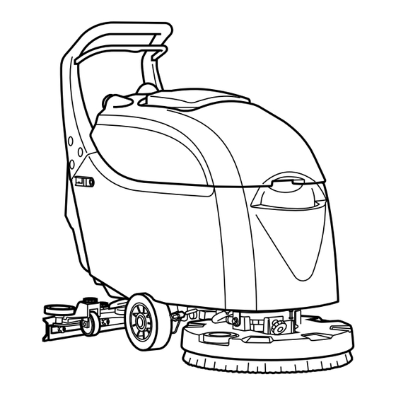
Introductory comment Serial number plate The MTECH 70 D is a floor scrubbing machine which, by means of the mechanical action of the rotating brush and the chemical action of a water/detergent solution, can clean any type of flooring. As it advances, it also collects any removed dirt as well as the detergent solution not absorbed by the floor. -
Page 8: Symbols Used On The Machine
SYMBOLS USED ON THE MACHINE Symbol for main switch or key switch (only for B-BT version). Used on the control panel, to indicate the key switch for machine operation on (I) or off (0). ECO mode symbol (only for B-BT version). Used on the control panel to indicate the button that activates the ECO mode of the machine. - Page 9 SYMBOLS USED ON THE MACHINE Traction motor potentiometer symbol (only for BT version). Used on the control panel to indicate the knob that commands the potentiometer that controls the traction motor. Main switch position "ON- SOLENOID VALVE" symbol (Only for BB version). Used on the control panel to indicate the button that commands the activation of the brush motor and the solenoid valve.
- Page 10 SYMBOLS USED ON THE MACHINE Symbol indicating the position of the solution tank drain cap. Symbol indicating the position of the solution tank filter. Symbol indicating the position of the recovery tank drainage tube Detergent flow control symbol. Used on the machine to indicate the position of the lever used to control the flow of the detergent solution present in the water system.
-
Page 11: General Safety Regulations
GENERAL SAFETY REGULATIONS The regulations below must be carefully followed in order to avoid harm to the operator and damage to the machine. WARNING: Read the labels on the machine carefully. Do not cover them for any reason and replace them immediately if they become damaged. - Page 12 Do not use the device to collect dangerous powders. Do not mix different types of detergent as this may produce harmful gases. The machine is not suitable for cleaning carpets. Do not place any liquid containers on the machine. ...
-
Page 13: Machine Preparation
Gross weight of machine with packaging: iMx version B: 94 kg MTECH 70 D: 101 kg iMx version BB: 94 kg The dimensions of the packaging are as follows: A= 1170mm... -
Page 14: How To Move The Machine
MACHINE PREPARATION 2. HOW TO MOVE THE MACHINE 1. Using a chute, mount the machine on the pallet. Carry out this operation with the rear squeegee and the brush detached from the machine. 2. Check the solution tank and recovery tank are empty; if necessary, empty them 3. -
Page 15: Control Panel Components (Version B)
MACHINE PREPARATION 5. Squeegee vacuum hose 6. Battery charger connector cable cap. 7. Recovery tank drainage tube 8. Control handlebar, with dead man's lever beneath. 9. Vacuum motor tube. 10. Recovery tank lifting handle. 11. Recovery tank cover 6. CONTROL PANEL COMPONENTS (VERSION B) The control panel components are identified as follows: 1. -
Page 16: Control Panel Components (Version Bb)
MACHINE PREPARATION 3. "ECO" function button. 4. Vacuum motor control button. 5. “AUTO” function button. 6. Reverse button 7. Proportional solenoid valve control button. 8. Brush coupling/uncoupling button. 8. CONTROL PANEL COMPONENTS (VERSION BB) The control panel components are identified as follows: 1. -
Page 17: Battery Maintenance And Disposal
MACHINE PREPARATION 10. BATTERY MAINTENANCE AND DISPOSAL For maintenance and recharging, respect the instructions provided by the battery manufacturer. Particular attention must be paid when choosing the battery charger, if not supplied, since there are different kinds according to the type and capacity of the battery. When the battery reaches the end of its working life, it must be disconnected by expert, trained personnel then removed from the battery compartment with the aid of suitable lifting devices. - Page 18 MACHINE PREPARATION 10.Remove the vacuum cover and attach to the support designed for this purpose, positioned at the rear of the machine. 11.Remove the recovery tank from the machine, taking care with the drainage hose, and rest on a raised surface in order to avoid accidental damage.
-
Page 19: Connecting The Batteries And Battery Connector
MACHINE PREPARATION 12. CONNECTING THE BATTERIES AND BATTERY CONNECTOR 1. Connect the batteries in series to the "+" and "-" poles using the supplied jumper cable (03). 2. Connect the battery connector cable (02) to the “+” and “-“ poles to obtain a voltage of 24V on the terminals. - Page 20 MACHINE PREPARATION 7. Remove the recovery tank drainage tube (01) and lay on the ground. 8. Remove the vacuum motor tube (05) from the connector present on the recovery tank. 9. Remove the squeegee vacuum hose (06) from the hole in the recovery tank. 10.
-
Page 21: Connecting The Battery Charger (Versions With Bc)
MACHINE PREPARATION 14. CONNECTING THE BATTERY CHARGER (VERSIONS WITH BC) In order not to cause permanent damage to the batteries, it is essential to avoid their complete discharge: arrange the recharge within a few minutes of the switching on of the "discharged batteries" blinking light. WARNING: Never leave the batteries completely discharged, even if the machine is not being used. -
Page 22: Battery Charge Level Indicator (B-Bt Versions)
MACHINE PREPARATION WARNING: Carefully read the use and maintenance manual of the charger that is delivered inside the bag containing this instruction booklet. WARNING: Before inserting the charger power cable into the socket, verify that there is no condensate or other forms of liquids. WARNING: If the machine's electric system is accidentally powered, the command display will show “BATTERY-CHARGER”... -
Page 23: Forward Work Speed (Bt Versions)
MACHINE PREPARATION 19. FORWARD WORK SPEED (BT VERSIONS) This machine is equipped with electronic traction control. To move the machine, after turning the key to position "I" simply push the dead man's lever, located under the grip of the handlebar. WARNING! The machine will not start to move (either forward or backward) if the potentiometer adjustment knob (01) is set to minimum. -
Page 24: Assembling The Squeegee
MACHINE PREPARATION WARNING: Always use detergents whose manufacturer's label indicates their suitability for scrubbing machines. Do not use acid or alkaline products or solvents without this indication. Acid or alkaline maintenance detergents can be used, as long as they have pH values between four and ten, and do not contain oxidising agents, chlorine or bromine, formaldehyde, mineral solvents. -
Page 25: Assembling The Brush (B-Bt Versions)
MACHINE PREPARATION 23. ASSEMBLING THE BRUSH (B-BT VERSIONS) To assemble the brushes of the brush head unit, proceed as follows: 1. Raise the brush head from the ground using the control handlebar. 2. Check that the squeegee is raised from the ground; if not, lift using the lever (01). 3. -
Page 26: Work
WORK 26. PREPARING TO WORK (B-BT VERSIONS) Before beginning to work, it is necessary to: 1. Make sure the recovery tank is empty, otherwise empty it completely. 2. Check that the quantity of detergent solution in the solution tank is correct for the type of work to be carried out;... - Page 27 WORK During the first few meters, check that the speed is appropriate to the work to be carried out; if not, adjust after reading the section "ADJUSTING WORKING SPEED" (valid only for BT versions). During the first few meters, check that the detergent solution is appropriate to the work to be carried out; if not, adjust after reading the section "REGULATING THE DETERGENT SOLUTION (B versions)”...
-
Page 28: Preparing To Work (Bb Versions)
WORK If only the drying function is needed, simply press the button (06) on the control panel and the brush motor, the vacuum motor and the solenoid valve will stop working immediately (the vacuum motor will effectively cease to function after approximately fifteen seconds). On pressing the button (08) the vacuum motor will start up again, and the machine can be used in drying mode. -
Page 29: Regulating The Detergent (B Version)
WORK If only the scrubbing function is needed, simply turn the button (04) on the control panel to "Pos.-02" and the vacuum motor will immediately cease to function. Once the scrubbing cycle is complete, turn the button (04) to "Pos.-01" to return to the scrub and dry function. -
Page 30: Regulating The Detergent (Bt Version)
WORK 29. REGULATING THE DETERGENT (BT VERSION) To regulate the detergent, proceed as follows: 1. Ensure that the tap flow is at maximum capacity by turning the lever (01) on the right-hand rear part of the machine anticlockwise. 2. Check that the quantity of detergent solution in the solution tank is correct for the type of work to be carried out;... -
Page 31: Adjusting The Forward Working Speed (Bt Versions)
WORK 31. ADJUSTING THE FORWARD WORKING SPEED (BT VERSIONS) Proceed as follows to adjust the forward speed with the potentiometer: 1. Check that the speed regulation knob (1) is set to minimum. 2. Check that the brush head and squeegee are lifted off the ground 3. -
Page 32: Overflow Device (B-Bt Versions)
WORK If during the scrubbing operation the dead man's lever is released, the traction motor (BT version), the brush motor and the solenoid valve will cease to function. On the control display, the "O" symbol will remain visible. WARNING: In order to recommence work, simply press the dead man's lever and the traction motor (BT version), brush motor and solenoid valve will restart. -
Page 33: Overflow Device (Bb Versions)
WORK 2. Raise the squeegee body from the ground by means of the lever (02) on the back of the machine. 3. Take the machine to the designated place for draining off the dirty water and empty the recovery tank, read the paragraph "EMPTYING THE RECOVERY TANK (B-BT versions)“... -
Page 34: At The End Of Work
AT THE END OF WORK 38. AT THE END OF WORK (B-BT VERSIONS) At the end of work, and before carrying out any type of maintenance, perform the following operations: 1. Switch off "AUTO" mode by pressing the button (01) on the instrument control panel. This will switch off the brush motor and the solenoid valve, while the vacuum motor will remain active for approximately 15 seconds before switching off automatically. - Page 35 AT THE END OF WORK 12. Attach the squeegee body to the squeegee connector. 13. Insert the vacuum hose (07) into the sleeve (08) on the squeegee body. 14. If necessary to empty the solution tank, unscrew the tap-filter (10) on the left-hand side of the machine, and when finished, re tighten.
-
Page 36: At The End Of Work (Bb Versions)
AT THE END OF WORK 39. AT THE END OF WORK (BB VERSIONS) At the end of work, and before carrying out any type of maintenance, perform the following operations: 1. Switch off the vacuum motor using the switch (01) positioned on the rear of the machine. 2. - Page 37 AT THE END OF WORK 11. Attach the squeegee body to the squeegee connector. 12. Insert the vacuum hose (07) into the sleeve (08) on the squeegee body. 13. If necessary to empty the solution tank, unscrew the tap-filter (10) on the left-hand side of the machine, and when finished, re tighten.
-
Page 38: Daily Maintenance
DAILY MAINTENANCE PERFORM ALL MAINTENANCE OPERATIONS IN SEQUENCE 40. CLEANING THE SOLUTION TANK FILTER - CAP In order to ensure a proper flow of detergent solution into the water circuit, proper cleaning of the solution tank filter is necessary. In order to do this, proceed as follows: 1. -
Page 39: Cleaning The Brush (B-Bt Versions)
DAILY MAINTENANCE 2. Disconnect the electrical connector (02) from the battery connector. 3. Engage the parking brake by means of the lever (03) on the right side of the machine (only for BT versions). 4. Remove the vacuum cover (04) and position on the support (05) designed for this purpose, positioned at the rear of the machine. -
Page 40: Cleaning The Brush (Bb Versions)
DAILY MAINTENANCE 43. CLEANING THE BRUSH (BB VERSIONS) To ensure effective floor cleaning, proper cleaning of the brush is necessary. In order to do this, proceed as follows: 1. Make sure the recovery tank is empty, otherwise empty it completely. 2. - Page 41 DAILY MAINTENANCE 5. Remove the vacuum hose (05) from the vacuum nozzle (06) on the squeegee body. 6. Loosen the knobs (07) in the squeegee body pre-assembly. 7. Remove the squeegee body from the slits in the squeegee connector. 8. First with a jet of water and then with a damp cloth, thoroughly clean the vacuum chamber of the squeegee body.
-
Page 42: Weekly Maintenance
WEEKLY MAINTENANCE 45. CLEANING THE VACUUM HOSE Whenever vacuum seems to be unsatisfactory, check that the vacuum hose is not obstructed. If necessary clean with a jet of water as follows: 1. Switch off the power supply to the machine's electrical system using the main switch (01) located on the rear of the machine, turning the key to position “0”... - Page 43 WEEKLY MAINTENANCE 1. Switch off the power supply to the machine's electrical system using the main switch (01) located on the rear of the machine, turning the key to position “0” (valid for versions B-BT). 2. Make sure the recovery tank is empty, otherwise empty it completely. 3.
-
Page 44: Cleaning The Solution Tank
WEEKLY MAINTENANCE 9. Turn the cup (09) anticlockwise and remove from the machine. 10. Remove the recovery tank filter (10). 11. Remove the recovery tank from the machine, taking extra care with the drainage hose. 12. Open the recovery tank drainage tube cap (06). 13. -
Page 45: Emergency Maintenance
EMERGENCY MAINTENANCE 48. ADJUSTING THE PARKING BRAKE (ONLY FOR BT VERSIONS) To avoid damage to the machine or to persons or objects nearby when placing the machine in rest mode, users are advised to check the condition of the parking brake, proceeding as follows: 1. -
Page 46: Regulating Machine Direction
EMERGENCY MAINTENANCE 3. Make sure that the main switch (02) is in the "II" position; if not, position it to "II". 4. Put the machine in rest mode. Using the control handlebar (pushing downwards), lift the front part of the machine so that the rear wheel rests on the floor. 5. -
Page 47: Adjusting The Squeegee Inclination
EMERGENCY MAINTENANCE 5. Remove the vacuum hose (05) from the vacuum nozzle (06) on the squeegee body. 6. Loosen the knobs (07) in the squeegee body pre-assembly. 7. Remove the squeegee body from the slits in the squeegee connector. WARNING: This operation must be carried out using gloves to protect against contact with dangerous solutions. -
Page 48: Troubleshooting
TROUBLESHOOTING 55. THE MACHINE DOES NOT START 1. Check that batteries are charged 2. Make sure the electric system connector is connected to the battery connector 3. Check that the key switch is in position “I” (B-BT versions). 56. INSUFFICIENT WATER ON THE BRUSHES 1. -
Page 49: Disposal
DISPOSAL To dispose of the machine, take it to a demolition centre or an authorised collection centre. Before scrapping the machine it is necessary to remove and separate the following materials and send them to the appropriate collection centres in accordance with the environmental hygiene regulations currently in force: ... -
Page 50: Choosing And Using The Brushes
CHOOSING AND USING THE BRUSHES POLYPROPYLENE BRUSH (PPL) Used on all types of floor, it has good resistance to wear and tear and hot water (no greater than 60°C). PPL is non-hygroscopic and therefore retains its characteristics even when working in wet conditions. NYLON BRUSH Used on all types of floors. -
Page 51: Ec Declaration Of Conformity
Sauber House, Unit 3, Rushington Business Park Chapel Lane, Totton, Hampshire, SO40 9AH Declares under its sole responsibility that the products FLOOR SCRUBBING MACHINES mod. MTECH 70 D comply with the requirements of the following Directives: • 2006/42/EC: Machinery Directive. • 2014/35/EC: Low Voltage Directive. - Page 52 NOTES...
- Page 53 NOTES...
- Page 54 NOTES...
- Page 56 Industrial Cleaning Equipment Ltd. Sauber House, Unit 3, Rushington Business Park - Chapel Lane, Totton, Hampshire, SO40 9AH Service 0800 389 3869 - Facsmile 023 8042 8318 - Email info@ice-clean.com...
Need help?
Do you have a question about the MTECH 70 D and is the answer not in the manual?
Questions and answers