
Subscribe to Our Youtube Channel
Related Manuals for Ice R-SCRUB 75D


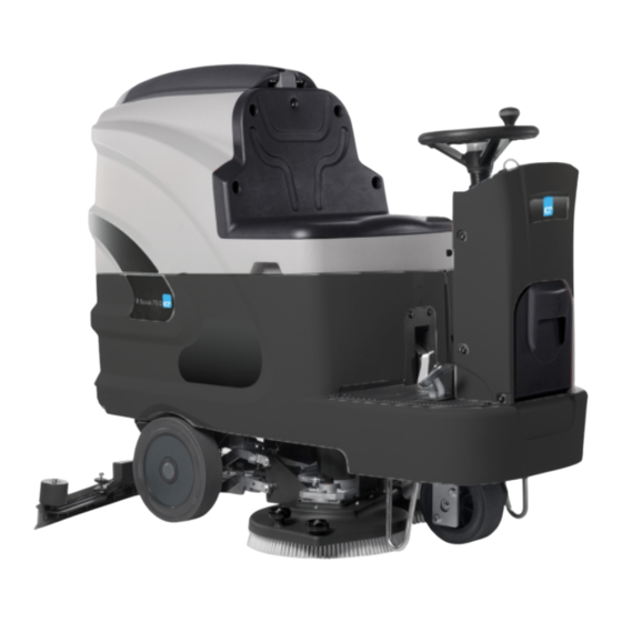
Summary of Contents for Ice R-SCRUB 75D
- Page 1 R-SCRUB 75-85 SCRUBBING MACHINES USE AND MAINTENANCE MANUAL ORIGINAL INSTRUCTION DOC. 10068677 - Ver. AA - 02-2017...
- Page 2 The descriptions contained in this document are not binding. The company therefore reserves the right to make any modifications at any time to elements, details, or accessory supply, as considered necessary for reasons of improvement or manufacturing/commercial requirements. The reproduction, even partial, of the text and drawings contained in this document is prohibited by law.
-
Page 3: Table Of Contents
CONTENTS ON CONSIGNMENT OF THE MACHINE................................5 INTENDED USE ........................................5 TECHNICAL DESCRIPTION....................................6 SYMBOLS USED ON THE MACHINE ................................7 MACHINE PREPARATION ....................................13 1. HANDLING THE PACKED MACHINE ....................................13 2. HOW TO UNPACK THE MACHINE ....................................13 ... - Page 4 73. THE MACHINE DOES NOT CLEAN WELL ..................................46 74. EXCESSIVE FOAM PRODUCTION ....................................46 75. THE VACUUM CLEANER DOES NOT FUNCTION ................................ 46 77. THE BRUSH MOTOR DOES NOT WORK ..................................46 78. IT IS IMPOSSIBLE TO RAISE OR LOWER THE BRUSH HEAD OR SQUEEGEE ......................46 ...
-
Page 5: On Consignment Of The Machine
On consignment of the machine Serial number plate The serial number plate is located at the rear of the steering column, When the machine is consigned to the customer, an immediate check and it contains the general characteristics of the machine, and in must be performed to ensure all the material mentioned in the shipping particular the machine's serial number. -
Page 6: Technical Description
R-SCRUB R-SCRUB TECHNICAL DESCRIPTION Working width Squeegee width 1085 Working capacity, up to 4500 5100 Disc brushes 2/390 2/430 Nr / mm Cylindrical brushes Nr / mm Brush rotations Revs/min. Brush motor 24/450 24/450 Maximum pressure on the brushes (min/max) 30/60 30/60 Traction motor... -
Page 7: Symbols Used On The Machine
SYMBOLS USED ON THE MACHINE Indicates the maximum gradient. Pedal labels that indicate the forward and reverse direction of the machine. Used to indicate the direction of the machine. Water quantity regulation symbol. Used on the steering column to indicate the knobs for adjusting the quantity of water distributed in the machine's water system. - Page 8 SYMBOLS USED ON THE MACHINE Main switch symbol (key switch). Used on the instrument panel, to indicate the key switch for machine operation on (ON/I) or off (OFF/0). Symbol that the brush head / squeegee are operating. Used to indicate the I-DRIVE program selector. Symbol for ECO mode.
- Page 9 SYMBOLS USED ON THE MACHINE Battery critical charge level symbol). Used on the control display to indicate the critical state of charge of the batteries and the need to recharge them. “DRYING” working program. Used in the control display to indicate that the “DRYING” working program is active, in this case only the vacuum motor is operating.
- Page 10 SYMBOLS USED ON THE MACHINE “ECO SCRUBBING-EXTRA PRESSURE” working program symbol. Used in the control display to indicate that the “ECO SCRUBBING-EXTRA PRESSURE” working program is active, in this case the brush motor and the solenoid valve are operating, but with the addition of more pressure on the brushes in economic mode.
- Page 11 GENERAL SAFETY REGULATIONS The regulations below must be carefully followed in order to avoid harm to the operator and damage to the machine. WARNING: Read the labels on the machine carefully. Do not cover them for any reason and replace them immediately if they become damaged.
- Page 12 Do not remove the guards that can only be removed with the aid of tools, except for maintenance work (see the relevant paragraphs) Do not wash the machine with direct water jets or with pressurised water, nor with corrosive substances. ...
-
Page 13: Machine Preparation
MACHINE PREPARATION 1. HANDLING THE PACKED MACHINE The machine is contained in specific packaging with a pallet for the handling with fork trucks. The packages cannot be placed on top of each other. Gross weight of machine with packaging is 268kg (without batteries) The dimensions of the packaging are as follows: A : 1635 mm B: 730 mm... -
Page 14: Instrument Panel Components
MACHINE PREPARATION 4. INSTRUMENT PANEL COMPONENTS The instrument panel components are identified as follows: Main key switch. Emergency switch. Working program adjustment switch, I-Drive device. Control display. Choose the desired working program with the I-Drive device: A. Transfer: movement of the machine without working. B. -
Page 15: Side Components Of The Machine
MACHINE PREPARATION Brake pedal. Parking brake lever. Brush head extra pressure pedal . Solution level pipe. 7. SIDE COMPONENTS OF THE MACHINE The side components of the machine are identified as follows: Water-detergent filler cap, water filler. Fast water filler cap. Optional kit for cleaning accessories. -
Page 16: Rear Components Of The Machine
MACHINE PREPARATION 8. REAR COMPONENTS OF THE MACHINE The rear components of the machine are identified as follows: Recovery tank drainage tube. Squeegee vacuum hose. 9. BATTERY TYPE To power the machine it is necessary to use: liquidelectrolyte lead traction batteries; ... -
Page 17: Connecting The Batteries And Battery Connector
MACHINE PREPARATION To insert the batteries into the compartment proceed as follows: Check that the recovery tank is empty; if not, empty it using the tube provided for this purpose (01) positioned at the rear of the machine (read the section "EMPTYING THE RECOVERY TANK"). Block the machine in place by engaging the parking brake, press the pedal (02) and block it with the lever (03) at the rear of the steering column (read the section “PARKING BRAKE AND SERVICE BRAKE”). - Page 18 MACHINE PREPARATION To connect the battery charger you must: Take the machine to the maintenance area. Check that the recovery tank is empty; if not, empty it using the tube provided for this purpose (01) positioned at the rear of the machine (read the section "EMPTYING THE RECOVERY TANK"). Block the machine in place buy engaging the parking brake, press the pedal (02) and block it with the lever (03) at the rear of the steering column (read the section “PARKING BRAKE AND SERVICE BRAKE”).
-
Page 19: Hour Meter
MACHINE PREPARATION 14. HOUR METER The control display is on the machine's instrument panel, the third screen after the machine has been started allows you to observe: In the first part of the display you can display the work voltage that has been set and the type of battery. - Page 20 MACHINE PREPARATION WARNING: The tanks should be emptied in the place used for draining dirty water. Block the machine in place buy engaging the parking brake, press the pedal (02) and block it with the lever (03) at the rear of the steering column (read the section “PARKING BRAKE AND SERVICE BRAKE”).
-
Page 21: Detergent Solution
MACHINE PREPARATION By using the rubber cap (03), which supports the water hose on its own, be sure to unscrew the cap (01) to allow the proper vent of air. By using the optional system (05) for automatically topping up with clean water, which has a float for controlling the overflow, be sure to unscrew the cap (01) to allow the proper vent of air. -
Page 22: Washing The Brush Head Casing Assembly
MACHINE PREPARATION Initially insert the right pin (04) of the squeegee into the right slot (05) of the squeegee attachment, making sure to keep the spring and the washer above the squeegee attachment plate. WARNING: This can be simplified by first loosening the handwheel (06) on the pin. Repeat the same operation also for the left pin. -
Page 23: Assembling The Brushes
MACHINE PREPARATION 21. ASSEMBLING THE BRUSHES To assemble the brushes, which for reasons of packaging are supplied dismantled from the machine, proceed as follows: 1. Block the machine in place by engaging the parking brake, press the pedal (01) and block it with the lever (02) at the rear of the steering column (read the section “PARKING BRAKE AND SERVICE BRAKE”). -
Page 24: Preparing To Work
PREPARING TO WORK 24. PREPARING TO WORK Before beginning to work, it is necessary to: 1. Make sure the recovery tank is empty, otherwise empty it completely. 2. Check that the quantity of detergent solution in the solution tank is correct for the type of work to be carried out;... -
Page 25: Work
WORK 25. STARTING TO WORK To start working, do as follows: Carry out all the checks in the chapter “PREPARING TO WORK”. Sit on the driver’s seat. Turn the main switch key (01) clockwise by a quarter of a turn to "I". The instrument panel display will immediately come on. - Page 26 WORK By selecting the "DRYING” program, the display screen shown on the side will appear. The brush head is raised from the floor and is not operating. The squeegee will position itself in contact with the floor as soon as the forward movement pedal is pressed, in that moment the vacuum motor will start working. WARNING: this program should only be used to collect the dirty solution after a pre- wash, and should never be used for the work of vacuuming liquids.
- Page 27 WORK By selecting the "SCRUBBING” program, the display screen will appear as in the adjacent figure. The squeegee is raised from the floor and is not operating. The brush head will position itself in contact with the floor as soon as the forward movement pedal is pressed, in that moment the vacuum motor will start working.
-
Page 28: Detergent Regulation
WORK Remove the parking brake, turn the lever (07) clockwise. The parking symbol “P” will disappear from the control panel display. WARNING: If you try to move forward with the parking brake engaged, the machine will not move because the motor wheel is disengaged electrically when the parking brake is active. -
Page 29: Eco" Device
WORK To display the speed level that has been set, just look at the symbol (02) on the display. 28. "ECO" DEVICE By activating “ECO MODE” mode using the relevant button (01) on the instrument panel, the energy used by the machine is reduced, decreasing the power of the brushes motor and the vacuum motor. Just press the button (01) on the instrument panel to deactivate the "ECO MODE"... -
Page 30: Overflow Device
WORK If, when working in "SCRUBBING - DRYING" mode, the extra pressure pedal is pressed, the control display will immediately undergo the change (02) shown in the image on the side. If, when working in "SCRUBBING" mode, the extra pressure pedal is pressed, the control display will immediately undergo the change (03) shown in the image on the side. - Page 31 AT THE END OF THE WORK At the end of work, and before carrying out any type of maintenance, perform the following operations: Take the machine to the designated place for draining off the dirty water. Bring the main machine switch to "0" by turning the key on the instrument panel a quarter rotation to the left.
- Page 32 AT THE END OF THE WORK Engage the parking brake, rotating the lever on the rear of the steering column clockwise. 10. Bring the main machine switch to "I" by turning the key on the instrument panel a quarter rotation to the right.
-
Page 33: Daily Maintenance
DAILY MAINTENANCE PERFORM ALL MAINTENANCE OPERATIONS IN SEQUENCE 31. EMPTYING THE RECOVERY TANK Proceed as follows to empty the recovery tank: Take the machine to the maintenance area, using the switch on the instrument panel select the program "TRANSPORT” (A). Block the machine in place by engaging the parking brake, press the pedal (01) and block it with the lever (02) at the rear of the steering column (read the section “PARKING BRAKE AND SERVICE BRAKE”). -
Page 34: Cleaning The Squeegee Body
DAILY MAINTENANCE Block the machine in place by engaging the parking brake, press the pedal (01) and block it with the lever (02) at the rear of the steering column (read the section “PARKING BRAKE AND SERVICE BRAKE”). Turn the main machine switch to "0" by turning the key (03) a quarter rotation to the left. Remove the key from the instrument panel. -
Page 35: Cleaning Disc Brushes
DAILY MAINTENANCE Remove the vacuum hose (04) from the vacuum nozzle (05) on the squeegee body. Loosen the knobs (06) in the squeegee body pre-assembly. Remove the squeegee body from the slits in the squeegee connector. First with a jet of water and then with a damp cloth, thoroughly clean the vacuum chamber (07) of the squeegee unit. -
Page 36: Cleaning The Recovery Tank Filter
DAILY MAINTENANCE Block the machine in place by engaging the parking brake, press the pedal (01) and block it with the lever (02) at the rear of the steering column (read the section “PARKING BRAKE AND SERVICE BRAKE”). WARNING: You are advised to always wear protective gloves, to avoid the risk of serious injury to your hands. - Page 37 DAILY MAINTENANCE Turn the main machine switch to "0" by turning the key (03) a quarter rotation to the left. Remove the key from the instrument panel. Raise the cap (04) until the hook (05) is secured to the prop (06) of the recovery tank. Remove the vacuum filter protection (07) by rotating it in a clockwise direction.
-
Page 38: Weekly Maintenance
WEEKLY MAINTENANCE 36. CLEANING THE RECOVERY TANK The careful cleaning of the recovery tank guarantees a longer machine life. Proceed as follows to clean the recovery tank: Take the machine to the maintenance area, using the switch on the instrument panel select the program "TRANSPORT”... -
Page 39: Cleaning The Water System Filter
WEEKLY MAINTENANCE Block the machine in place by engaging the parking brake, press the pedal (01) and block it with the lever (02) at the rear of the steering column (read the section “PARKING BRAKE AND SERVICE BRAKE”). Turn the main machine switch to "0" by turning the key (03) a quarter rotation to the left. Remove the key from the instrument panel. -
Page 40: Cleaning Of The Vacuum Hose
WEEKLY MAINTENANCE Block the machine in place by engaging the parking brake, press the pedal (01) and block it with the lever (02) at the rear of the steering column (read the section “PARKING BRAKE AND SERVICE BRAKE”). Turn the main machine switch to "0" by turning the key (03) a quarter rotation to the left. Remove the key from the instrument panel. - Page 41 WEEKLY MAINTENANCE Remove the vacuum hose (04) from the vacuum nozzle (05) on the squeegee body. Grip the handle on the right side of the recovery tank. Lift the recovery tank until it hooks to the end of the safety catch. Remove the vacuum hose (06) from the recovery tank.
-
Page 42: Extraordinary Maintenance
EXTRAORDINARY MAINTENANCE 40. REPLACING THE SQUEEGEE RUBBER Careful cleaning of the squeegee rubber guarantees better cleaning of the floor as well as a longer vacuum motor life. To charge the squeegee rubber proceed as follows: Take the machine to the maintenance area, using the switch on the control panel select the program "TRANSPORT”... -
Page 43: Regulating The Squeegee
EXTRAORDINARY MAINTENANCE 41. REGULATING THE SQUEEGEE Careful adjustment of the height between the squeegee rubber and the floor guarantees better drying and cleaning of the floor as well as a longer vacuum motor life. To regulate the squeegee rubber proceed as follows: Using the switch on the instrument panel, select the program “SCRUBBING - DRYING"... -
Page 44: Replacing The Brush Head Casing
EXTRAORDINARY MAINTENANCE Block the machine in place by engaging the parking brake, press the pedal (01) and block it with the lever (02) at the rear of the steering column (read the section “PARKING BRAKE AND SERVICE BRAKE”). WARNING: You are advised to always wear protective gloves, to avoid the risk of serious injury to your hands. - Page 45 EXTRAORDINARY MAINTENANCE 7. Remove the casing to be replaced (04) from the brush head unit, the casing is fixed to it by means of screws (05). The image on the side shows the left casing. 8. Secure the new casing to the brush head unit (read the section "ASSEMBLING THE BRUSH HEAD CASING").
-
Page 46: Troubleshooting
TROUBLESHOOTING 44. INSUFFICIENT WATER ON THE BRUSHES Check that there is water in the solution tank, the amount inside the tank can be seen by means of the level tube (01) on the front left of the seat. Make sure that the detergent solution tap is open, and check that the knob (02) on the back of the steering column is completely lowered. -
Page 47: The Machine Does Not Start
TROUBLESHOOTING 51. THE MACHINE DOES NOT START Check the connector is connected to the batteries. Check the key switch (01) is on "I". Check that the batteries are charged, control the symbol (02) on the control display. 52. ELECTRIC FUSES AND THERMAL CUT-OUTS In addition to general 80 A fuses, the machine is also fitted with self-restoring safety fuses located on the boards in the electric system that interrupt the power supply to the brush and vacuum motor when the machine exceeds the predetermined load. -
Page 48: Disposal
DISPOSAL To dispose of the machine, take it to a demolition centre or an authorised collection centre. Before scrapping the machine it is necessary to remove and separate the following materials and send them to the appropriate collection centres in accordance with the environmental hygiene regulations currently in force: ... -
Page 49: Choosing And Using The Brushes
TABLE FOR CHOOSING THE BRUSHES Machine No. of Code Type of bristles Length Notes Bristles Brush brushes 427715 427716 R-SCRUB 75D 427717 427719 ABRASIVE 427718 PAD HOLDER 430696 430697 R-SCRUB 85D 430698 430699 ABRASIVE... - Page 50 Chapel Lane, Totton, Hampshire, SO40 9AH Declares under its sole responsibility that the products FLOOR SCRUBBING MACHINES mod. R-SCRUB 75D - R-SCRUB 85D comply with the requirements of the following Directives: • 2006/42/EC: Machinery Directive. • 2014/35/EC: Low Voltage Directive.
- Page 52 Industrial Cleaning Equipment Ltd. Sauber House, Unit 3, Rushington Business Park - Chapel Lane, Totton, Hampshire, SO40 9AH Service 0800 389 3869 - Facsmile 023 8042 8318 - Email info@ice-clean.com...
Need help?
Do you have a question about the R-SCRUB 75D and is the answer not in the manual?
Questions and answers