Table of Contents
Advertisement
Quick Links
Operation and Maintenance Manual
Benchmark
Natural Gas, Propane Gas and Dual Fuel Fired
Modulating & Condensing Boilers
Models 5000 and 6000
Other documents for this product include:
OMM-0117, GF-202 Installation & Startup Manual
TAG-0019, GF-2070 Boiler Application Guide
TAG-0022, GF-2050 Vent-Combustion Air Guide
TAG-0047, GF-2030 Benchmark Gas Guide
TAG-0048, GF-2060 Benchmark Power Guide
Applies to serial numbers:
N-19-0001 and above
Disclaimer
The information contained in this manual is subject to change without notice
from AERCO International, Inc. AERCO makes no warranty of any kind with
respect to this material, including, but not limited to, implied warranties of
merchantability and fitness for a particular application. AERCO International is
not liable for errors appearing in this manual, not for incidental or consequential
damages occurring in connection with the furnishing, performance, or use of
these materials
OMM-0118_B • GF-203 • 5/9/2019
Boilers
®
Advertisement
Table of Contents
Troubleshooting

Subscribe to Our Youtube Channel
Related Manuals for Watts Aerco Benchmark OMM-0117


Summary of Contents for Watts Aerco Benchmark OMM-0117
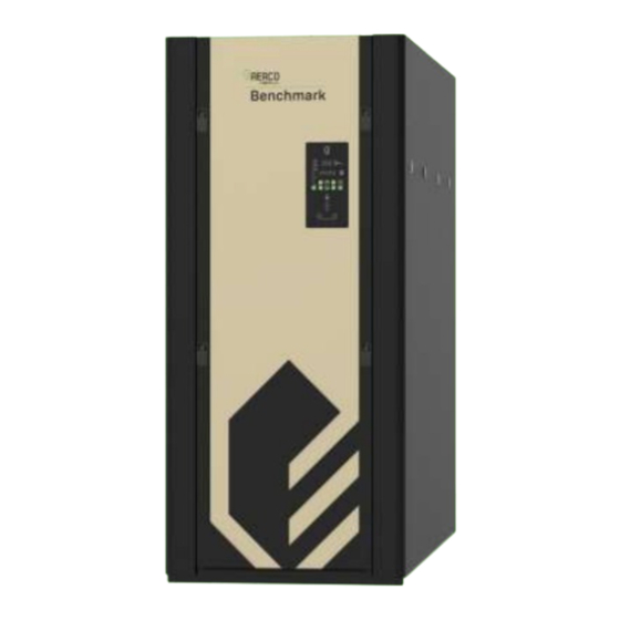
- Page 1 Operation and Maintenance Manual Benchmark Boilers ® Natural Gas, Propane Gas and Dual Fuel Fired Modulating & Condensing Boilers Models 5000 and 6000 Other documents for this product include: OMM-0117, GF-202 Installation & Startup Manual TAG-0019, GF-2070 Boiler Application Guide TAG-0022, GF-2050 Vent-Combustion Air Guide TAG-0047, GF-2030 Benchmark Gas Guide TAG-0048, GF-2060 Benchmark Power Guide...
-
Page 2: Table Of Contents
Benchmark 5000-6000 Operation & Maintenance Manual CONTENTS TABLE OF CONTENTS FOREWORD ...................... 5 SECTION 1: SAFETY PRECAUTIONS ..............9 1.1 WARNINGS & CAUTIONS ........................9 1.2 EMERGENCY SHUTDOWN ......................... 10 1.3 PROLONGED SHUTDOWN ......................... 10 1.4 IMPORTANT – FOR MASSACHUSETTS INSTALLATIONS ............... 11 SECTION 2: OPERATION ................. - Page 3 Benchmark 5000-6000 Operation & Maintenance Manual CONTENTS 4.5.1 Pilot Regulator Pressure Testing ........................44 4.5.2 Pilot Regulator Pressure Calibration ....................... 46 4.6 SAFETY DEVICE TESTING ......................... 47 4.7 BURNER INSPECTION ........................48 4.8 REFRACTORY REMOVAL & REPLACEMENT ................... 51 4.8.1 Rear Refractory Removal and Replacement ....................51 4.8.2 Front Refractory Replacement ........................
- Page 4 Benchmark 5000-6000 Operation & Maintenance Manual CONTENTS APPENDIX H: C-MORE CONTROLLER VIEWS ............ 141 APPENDIX I: RECOMMENDED SPARES ............143 APPENDIX J: LONG TERM BLOWER STORAGE ..........145 OMM-0118_B • GF-203 • 5/9/2019 Technical Support • (800) 526-0288 • Mon-Fri, 8 am - 5 pm EST Page 4 of 148...
-
Page 5: Foreword
Benchmark 5000-6000 Operation & Maintenance Manual FORWARD FOREWORD The AERCO Benchmark (BMK) 5000 MBH (1465 kW) and 6000 MBH (1758 kW) natural gas and dual fuel propane/natural gas fueled boilers are modulating and condensing units. They represent a true industry advance that meets the needs of today's energy and environmental concerns. - Page 6 Benchmark 5000-6000 Operation & Maintenance Manual FORWARD AERCO Technical Terminology TERMINOLOGY MEANING A (Amp) Ampere AERCO Control System, AERCO’s boiler management systems ADDR Address AGND Analog Ground ALRM Alarm ANSI American National Standards Institute, ASME American Society of Mechanical Engineers Auxiliary Building Automation System, often used interchangeably with EMS (see below)
- Page 7 Benchmark 5000-6000 Operation & Maintenance Manual FORWARD AERCO Technical Terminology TERMINOLOGY MEANING Ground Header Hexadecimal Number (0 – 9, A – F) Horse Power Heat Exchanger Hertz (Cycles Per Second) I.D. Inside Diameter Ignition IGST Board Ignition/Stepper Board, contained in C-More Controller INTLK (INTL’K) Interlock Input/Output...
- Page 8 Benchmark 5000-6000 Operation & Maintenance Manual FORWARD AERCO Technical Terminology TERMINOLOGY MEANING Pounds per Square Inch (1 PSI = 6.89 kPa) Point-to-Point (usually over RS232 networks) P&T Pressure and Temperature ProtoNode Hardware interface between BAS and a boiler or water heater Poly Vinyl Chloride, a common synthetic plastic Pulse Width Modulation REF (Ref)
-
Page 9: Section 1: Safety Precautions
Benchmark 5000-6000 Operation & Maintenance Manual SECTION 1: SAFETY PRECAUTIONS SECTION 1: SAFETY PRECAUTIONS 1.1 WARNINGS & CAUTIONS Installers and operating personnel MUST, at all times, observe all safety regulations. The following warnings and cautions are general and must be given the same attention as specific precautions included in these instructions. -
Page 10: Emergency Shutdown
Benchmark 5000-6000 Operation & Maintenance Manual SECTION 1: SAFETY PRECAUTIONS 1.2 EMERGENCY SHUTDOWN If overheating occurs or the gas supply fails to shut off, close the manual gas shutoff valve (Figure 1-1) located external to the unit. NOTE: The Installer must identify and indicate the location of the emergency shutdown manual gas valve to operating personnel. -
Page 11: Important - For Massachusetts Installations
Benchmark 5000-6000 Operation & Maintenance Manual SECTION 1: SAFETY PRECAUTIONS 1.4 IMPORTANT – FOR MASSACHUSETTS INSTALLATIONS REQUIREMENTS FOR MASSACHUSETTS INSTALLATIONS Boiler Installations within the Commonwealth of Massachusetts must conform to the following requirements: • Boiler must be installed by a plumber or a gas fitter who is licensed within the Commonwealth of Massachusetts. - Page 12 Benchmark 5000-6000 Operation & Maintenance Manual SECTION 1: SAFETY PRECAUTIONS REQUIREMENTS FOR MASSACHUSETTS INSTALLATIONS 4. INSPECTION: The state or local gas inspector of the side wall horizontally vented gas fueled equipment shall not approve the installation unless, upon inspection, the inspector observes carbon monoxide detectors and signage installed in accordance with the provisions of 248 CMR 5.08(2)(a)1 through 4.
-
Page 13: Section 2: Operation
Benchmark 5000-6000 Operation & Maintenance Manual SECTION 2: OPERATION SECTION 2: OPERATION 2.1 INTRODUCTION The information in this section provides a guide to the operation of the Benchmark Boiler using the C-More Controller mounted on the front of the unit. It is imperative that the initial startup of this unit be performed by factory trained personnel. -
Page 14: C-More Controller Description
Benchmark 5000-6000 Operation & Maintenance Manual SECTION 2: OPERATION 2.2 C-MORE CONTROLLER DESCRIPTION All Benchmark boilers utilize the C-More Controller’s front panel, shown in Figure 2-1. This panel contains all of the controls, indicators and displays necessary to operate, adjust and troubleshoot the boiler. - Page 15 Benchmark 5000-6000 Operation & Maintenance Manual SECTION 2: OPERATION TABLE 2-1: Controls, Indicators, and Displays (ref. Figure 2-1) CONTROL, INDICATOR ITEM FUNCTION or DISPLAY LED STATUS INDICATORS Four Status LEDs indicate the current operating status as follows: Lights when RS232 communication is occurring – see Item 4. COMM = Lights when the valve position (fire rate) is being controlled using the front MANUAL =...
- Page 16 Benchmark 5000-6000 Operation & Maintenance Manual SECTION 2: OPERATION TABLE 2-1: Controls, Indicators, and Displays (ref. Figure 2-1) CONTROL, INDICATOR ITEM FUNCTION or DISPLAY MENU KEYPAD Six (6) keys which provide the following functions for the C- menus: More Controller Steps through the main menu categories, shown in Figure 2-2, below.
-
Page 17: C-More Controller Menus
Benchmark 5000-6000 Operation & Maintenance Manual SECTION 2: OPERATION 2.3 C-MORE CONTROLLER MENUS The C-More Controller incorporates an extensive menu structure which permits the operator to set up, and configure the unit. The menu structure consists of five major menu categories which are applicable to this manual. - Page 18 Benchmark 5000-6000 Operation & Maintenance Manual SECTION 2: OPERATION * Boiler Sequencing Technology Boiler Sequencing Technology (BST) appears only if enabled. See Section 6 in the Benchmark 5000 – 6000 Installation and Startup Guide, OMM-0117 (GF-202) for instructions. Figure 2-2: Menu Structure NOTE: The following sections provide brief descriptions of the options contained in each menu.
-
Page 19: Operating Menu
Benchmark 5000-6000 Operation & Maintenance Manual SECTION 2: OPERATION 2.4 OPERATING Menu The Operating menu displays a number of key operating parameters for the unit. All items in this menu except O2 Monitor (item 15) are “Read-Only” and cannot be changed. This menu can be accessed without entering a password. -
Page 20: Setup Menu
Benchmark 5000-6000 Operation & Maintenance Manual SECTION 2: OPERATION 2.5 SETUP Menu The Setup menu (Table 2-3) permits the operator to enter the unit password (159) which is required to change the menu options. To prevent unauthorized use, the password will time-out after 1 hour. -
Page 21: Configuration Menu
Benchmark 5000-6000 Operation & Maintenance Manual SECTION 2: OPERATION 2.6 CONFIGURATION Menu The Configuration menu shown in Table 2-4 permits adjustment of the Internal Setpoint (Setpt) temperature regardless of whether the valid password has been entered. Setpt is required for operation in the CONSTANT SETPOINT mode. - Page 22 Benchmark 5000-6000 Operation & Maintenance Manual SECTION 2: OPERATION TABLE 2-4: CONFIGURATION Menu AVAILABLE CHOICES OR LIMITS MENU ITEM DISPLAY DEFAULT Minimum Maximum Setpt Hi Limit Setpt Lo Limit 210°F (98.9° 180°F (82.2°C) Temp Hi Limit 40°F (4.4° 210°F (98.9° 195°F (90.6°...
-
Page 23: Tuning Menu
Benchmark 5000-6000 Operation & Maintenance Manual SECTION 2: OPERATION 2.7 TUNING Menu The Tuning menu items in Table 2-5 are Factory set for each individual unit. Do not change these menu entries unless specifically requested to do so by factory-trained personnel. TABLE 2-5: TUNING Menu AVAILABLE CHOICES OR LIMITS MENU ITEM DISPLAY... -
Page 24: Bst (Boiler Sequencing Technology) Menu
Benchmark 5000-6000 Operation & Maintenance Manual SECTION 2: OPERATION 2.9 BST (Boiler Sequencing Technology) Menu The BST menu must be enabled in order to be displayed and accessed. The BST Menu item, located at the end of the Configuration menu (item 37 in Table 2-4), must be se to Enabled. The BST menu contains all of the items required to configure, operate and monitor the functionality of the BST System. - Page 25 Benchmark 5000-6000 Operation & Maintenance Manual SECTION 2: OPERATION TABLE 2-7: BST Menu AVAILABLE CHOICES OR LIMITS MENU ITEM DISPLAY DEFAULT Minimum Maximum Mdbus Temp Units Degrees C or Degrees F Degrees C Header Temp Addr Header Temp Point BST Outdoor Sens Disabled Enabled Disabled...
- Page 26 Benchmark 5000-6000 Operation & Maintenance Manual SECTION 2: OPERATION TABLE 2-7: BST Menu AVAILABLE CHOICES OR LIMITS MENU ITEM DISPLAY DEFAULT Minimum Maximum BST Setpt HI Limit BST Setpt Lo Limit 220°F (104.4°C) 195°F (90.6°C) BST Prop Band 1°F (-17.2°C) 120°F (48.9°C) 100°F (37.8°C) BST Intgral Gain...
-
Page 27: Calibration Menu
Benchmark 5000-6000 Operation & Maintenance Manual SECTION 2: OPERATION * NOTE: The 1 BST Units 8 menu item shows the current status for each unit controlled by BST, up to a maximum of 8 units. The possible characters displayed are: - = Off Line * = Not Available (fault, etc.) 0 = Off... - Page 28 Benchmark 5000-6000 Operation & Maintenance Manual SECTION 2: OPERATION TABLE 2-8: Calibration Menu AVAILABLE CHOICES OR LIMITS MENU ITEM DISPLAY DEFAULT Minimum Maximum Exhst Module Temp 100 °F 500 °F 190 °F Exhst Warn Temp 100 °F 500 °F 180 °F Exhst Tmp VP Adj Exhst Adj Rate VP Change Rate...
- Page 29 Benchmark 5000-6000 Operation & Maintenance Manual SECTION 2: OPERATION TABLE 2-8: Calibration Menu AVAILABLE CHOICES OR LIMITS MENU ITEM DISPLAY DEFAULT Minimum Maximum Inlet Air Offset Inlet Wtr Offset Outlet Wtr Offset 24 hr Max Cycles 9999 24 hr Max Ovrtemp 9999 0-10v Out Test 10.0...
-
Page 30: Section 3: Modes Of Operation
Benchmark 5000-6000 Operation & Maintenance Manual SECTION 3 – MODES OF OPERATION SECTION 3: MODES OF OPERATION Benchmark boilers are capable of being operated in any one of six different modes. The following sections provide descriptions of each of these operating modes. Each boiler is shipped from the factory tested and configured for the ordered mode of operation. -
Page 31: Indoor/Outdoor Startup
Benchmark 5000-6000 Operation & Maintenance Manual SECTION 3 – MODES OF OPERATION 3.1.4 Indoor/Outdoor Startup Startup in the INDOOR/OUTDOOR RESET mode is accomplished as follows: NOTE: A design engineer typically provides design outdoor air temperature and supply header temperature data. Indoor / Outdoor Setup Instructions 1. -
Page 32: Setting The Setpoint
Benchmark 5000-6000 Operation & Maintenance Manual SECTION 3 – MODES OF OPERATION 3.2.1 Setting the Setpoint The setpoint temperature of the unit is adjustable from 40°F to 240°F (4.4°C to 115.6°C). To set the unit for operation in the CONSTANT SETPOINT mode, the following menu settings must be made in the Configuration menu: TABLE 3-1: Constant Setpoint Mode Settings MENU OPTION... -
Page 33: Remote Setpoint Field Wiring
Benchmark 5000-6000 Operation & Maintenance Manual SECTION 3 – MODES OF OPERATION If the Network setting is selected for RS-485 Modbus operation, a valid Comm Address must be entered in the Setup menu. Refer to Modbus Communication Manual GF-114 for additional information. -
Page 34: Direct Drive Field Wiring
Benchmark 5000-6000 Operation & Maintenance Manual SECTION 3 – MODES OF OPERATION NOTE: If a voltage, rather than current signal is used to control the remote setpoint, a DIP switch adjustment must be made on the CPU Board located in the C-More Controller Assembly. Contact your local AERCO representative for details. -
Page 35: Aerco Control System (Acs)
Benchmark 5000-6000 Operation & Maintenance Manual SECTION 3 – MODES OF OPERATION 3.5 AERCO CONTROL SYSTEM (ACS) NOTE: ACS is for installations with 9 or more boilers. It utilizes only RS-485 signaling to the boiler. Installations with 1 to 8 boilers can use Boiler Sequencing Technology (see Section 6 in Benchmark 5000 –... -
Page 36: Combination Control System (Ccs)
Benchmark 5000-6000 Operation & Maintenance Manual SECTION 3 – MODES OF OPERATION 3.6 COMBINATION CONTROL SYSTEM (CCS) NOTE: Only ACS can be utilized for the Combination Control System. A Combination Control System (CCS) is one that uses multiple boilers to cover both space- heating and domestic hot water needs. -
Page 37: Combination Control System Field Wiring
Benchmark 5000-6000 Operation & Maintenance Manual SECTION 3 – MODES OF OPERATION 3.6.1 Combination Control System Field Wiring Wiring for this system is between the ACS, the ACS Relay Box, and the terminals in the I/O Box. Wire the units using a shielded twisted pair of 18 to 22 AWG wire. When wiring multiple units, each unit’s wiring must conform to the above. -
Page 38: Section 4: Maintenance
Benchmark 5000-6000 Operation & Maintenance Manual SECTION 4 – MAINTENANCE SECTION 4: MAINTENANCE 4.1 MAINTENANCE SCHEDULE The unit requires regular routine maintenance to keep up efficiency and reliability. For best operation and life of the unit, routine maintenance procedures should be performed in the time periods specified in Table 4-1. -
Page 39: Pilot Burner
Benchmark 5000-6000 Operation & Maintenance Manual SECTION 4 – MAINTENANCE Kit P/N Description 12 Month service 58025-11 Services Pilot Burner, Flame Rod & Condensate trap 58025-11 plus: Burner, LWCO, Air Pump Filter & Air Filter 58025-12 24-Month Waterside/ replacement Fireside service 58025-15 Same as 58025-12 except clean (not replace) Air Filter 58025-14... - Page 40 Benchmark 5000-6000 Operation & Maintenance Manual SECTION 4 – MAINTENANCE To inspect/replace the Pilot Burner and/or Pilot Burner Rod, perform the following procedure: Pilot Burner Maintenance Instructions 1. Set the C-More Controller’s ON/OFF switch to the OFF position. Disconnect AC power from the unit.
-
Page 41: Main Flame Detector
Benchmark 5000-6000 Operation & Maintenance Manual SECTION 4 – MAINTENANCE 4.3 MAIN FLAME DETECTOR The Main Flame Detector (Replacement Kit P/N 65182) is located on the Blower Flange near the top of the unit (see Figure 4-1a, above). The Main Flame Detector may be hot. Allow the unit to cool sufficiently before removing the Main Flame Detector. - Page 42 Benchmark 5000-6000 Operation & Maintenance Manual SECTION 4 – MAINTENANCE Sensor Maintenance Instructions 4. Next, loosen and remove the O sensor and crush washer from the back plate using a 15/16" open-end wrench. 5. Thoroughly inspect the O2 sensor. If corroded, the sensor should be replaced. Ensure that the hole in the refractory is clean and that the gas sample suction tube is not clogged.
- Page 43 Benchmark 5000-6000 Operation & Maintenance Manual SECTION 4 – MAINTENANCE 4.4.1 Air Eductor Air Pump Maintenance Benchmark 5000 and 6000 units contain an Air Eductor assembly, mounted on the opening in unit’s back panel, just behind the 0 Sensor Cover (see Figure 4-2, above). It includes an air pump, which draws an air sample from the combustion chamber, causing it to flow past the Oxygen sensor mounted on the burner’s rear plate, ensuring its accuracy (see Air Pump Voltage setting in the Operating menu, Appendix A1 for more information).
-
Page 44: Combustion Calibration & Pilot Regulator Adjustment
Benchmark 5000-6000 Operation & Maintenance Manual SECTION 4 – MAINTENANCE 4.5 COMBUSTION CALIBRATION & PILOT REGULATOR ADJUSTMENT Combustion settings must be checked at the intervals shown in Table 4-1 as part of the maintenance requirements. Refer to Section 4.5 of the Benchmark 5000 – 6000 Installation and Startup Guide, OMM-0117 (GF-202)for combustion calibration instructions. - Page 45 Benchmark 5000-6000 Operation & Maintenance Manual SECTION 4 – MAINTENANCE Pilot Regulator Pressure Test Procedure Instructions MANUAL PILOT SHUT-OFF SOLENOID VALVE VALVES TO AIR/FUEL PILOT VALVE REGULATOR TEE WITH 1/4" NPT PLUG Install manometer here for Pilot Regulator tests GAS INLET UPSTREAM LOW HIGH GAS PRESSURE SWITCH GAS PRESSURE SWITCH...
-
Page 46: Pilot Regulator Pressure Calibration
Benchmark 5000-6000 Operation & Maintenance Manual SECTION 4 – MAINTENANCE 4.5.2 Pilot Regulator Pressure Calibration The instructions in this section apply to both the Natural Gas and Propane gas trains. If either the Natural Gas or Propane Pilot Regulator pressure is below 4.6” W.C. (1.15 kPa) or above 5.0”... -
Page 47: Safety Device Testing
Benchmark 5000-6000 Operation & Maintenance Manual SECTION 4 – MAINTENANCE Pilot Regulator Pressure Calibration Procedure Instructions 17. OPEN the external gas supply upstream of the unit. 18. Ensure power is restored and the boiler is turned on in the MANUAL mode. 19. -
Page 48: Burner Inspection
Benchmark 5000-6000 Operation & Maintenance Manual SECTION 4 – MAINTENANCE 4.7 BURNER INSPECTION The Burner assembly is located at the front of the unit's heat exchanger. The Burner assembly may be hot. Therefore, allow the unit to cool sufficiently before removing the Burner assembly. The following parts will be required for reassembly after Burner inspection: BMK 750/1000 Burner Inspection Parts PART NO. - Page 49 Benchmark 5000-6000 Operation & Maintenance Manual SECTION 4 – MAINTENANCE BMK 5000/6000 Burner Inspection Instructions 18. Remove the Blower from the Burner by pulling outward. Be careful not to allow it to swing and damage other equipment components. Refer to the exploded view in Figure 4-6. 19.
- Page 50 Benchmark 5000-6000 Operation & Maintenance Manual SECTION 4 – MAINTENANCE BMK 5000/6000 Burner Inspection Instructions TURNBUCKLE BLOWER BLOCKED INLET SWITCH 3/8-16 NUTS (6) BLOWER PROOF SWITCH 5/8-11 BOLTS (4) (A/F VALVE TO GAS TRAIN) AIR/FUEL VALVE GAS TRAIN SOME COMPONENTS REMOVED FOR CLARITY GAS TRAIN...
-
Page 51: Refractory Removal & Replacement
Benchmark 5000-6000 Operation & Maintenance Manual SECTION 4 – MAINTENANCE 4.8 REFRACTORY REMOVAL & REPLACEMENT WARNING! The heat exchanger insulation utilizes ceramic fiber material. Wear a fitted NIOSH-approved particulate respirator (3m n95 or equiv.) When servicing the heat exchanger and burner assemblies. - Page 52 Benchmark 5000-6000 Operation & Maintenance Manual SECTION 4 – MAINTENANCE Rear Refractory Replacement Instructions SENSOR COVER LOCATION (cover removed) SPRING LATCH AIR EDUCTOR Access the rear panel nuts (behind arrows) are on the RIGHT REAR PANEL rail & base inside the unit, accessible after removing the side panel on each side.
- Page 53 Benchmark 5000-6000 Operation & Maintenance Manual SECTION 4 – MAINTENANCE Rear Refractory Replacement Instructions IMPORTANT! If the rear refractory (P/N 83027) was damaged during removal, it should be replaced with a new part. If rear refractory replacement is required, a 2 hour burn-in period at a 30% fire rate must be performed to drive off organic binders.
-
Page 54: Front Refractory Replacement
Benchmark 5000-6000 Operation & Maintenance Manual SECTION 4 – MAINTENANCE Rear Refractory Replacement Instructions WARNING! The heat exchanger insulation utilizes ceramic fiber material. Wear a fitted NIOSH- approved particulate respirator (3m n95 or equiv.) When servicing the heat exchanger and burner assemblies. -
Page 55: Condensate Drain Trap
Benchmark 5000-6000 Operation & Maintenance Manual SECTION 4 – MAINTENANCE 4.9 CONDENSATE DRAIN TRAP Benchmark boilers contain a condensate trap (P/N 24441), located external to the unit and attached to the drain connection from the exhaust manifold (the location on the unit is shown in Figure 2-8 of the Benchmark 5000 –... -
Page 56: Air Filter Cleaning And Replacement
Benchmark 5000-6000 Operation & Maintenance Manual SECTION 4 – MAINTENANCE 4.10 AIR FILTER CLEANING and REPLACEMENT Benchmark 5000 and 6000 boilers are equipped with two air filters which should be cleaned and re-oiled every 12 months (Cleaning Kit P/N 58041) and replaced every 24 months (P/N 88014),. The air filter is located at the air fuel valve inlet, as shown in Figure 4-11. -
Page 57: Low Water Cutoff (Lwco) Capacitor Test
Benchmark 5000-6000 Operation & Maintenance Manual SECTION 4 – MAINTENANCE 4.11 LOW WATER CUTOFF (LWCO) CAPACITOR TEST The LWCO capacitor should be tested for electrical shorts every 12 months and replaced, then tested, every 24 months. The LWCO capacitor integrity test consists of two parts as described in the next two sections. -
Page 58: Low Water Cutoff (Lwco) - Capacitor Electrical Short Test
Benchmark 5000-6000 Operation & Maintenance Manual SECTION 4 – MAINTENANCE 4.11.1 Low Water Cutoff (LWCO) - Capacitor Electrical Short Test This test determines if there is an electrical short between the LWCO capacitor and the heat exchanger. Perform the capacitor electrical short test as described below. Low Water Cutoff –... -
Page 59: Low Water Cutoff (Lwco) - Standard C-More Controller Test
Benchmark 5000-6000 Operation & Maintenance Manual SECTION 4 – MAINTENANCE Low Water Cutoff – Capacitor Electrical Short Test Instructions 5. Confirm that the ohmmeter does NOT read a short. NOTE: If the ohmmeter reads a short, the capacitor assembly needs to be replaced. Refer to document TID-0096, provided with the 24-month maintence kit, for LWCO replacement instructions. -
Page 60: Placing The Boiler Back In Service After Aprolonged Shutdown
Benchmark 5000-6000 Operation & Maintenance Manual SECTION 4 – MAINTENANCE 4.13 PLACING THE BOILER BACK IN SERVICE AFTER A PROLONGED SHUTDOWN After a prolonged shutdown (one year or more), the following procedures must be followed: Placing the Boiler Back In Service After Prolonged Shutdown Instructions 1. -
Page 61: Gas Valve Actuator Replacement
Benchmark 5000-6000 Operation & Maintenance Manual SECTION 4 – MAINTENANCE 4.14 GAS VALVE ACTUATOR REPLACEMENT If you need to replace the gas valve actuator, see TID-0092 for Actuator Replacement Kit P/N 27086-TAB. If you are replacing a newer actuator (P/N 124138), the wiring is unchanged. However, complete the instructions below only if you are replacing an older actuator (P/N 69171, shown in Figure 4-15 below) to change the wiring to accept the new actuator. -
Page 62: Section 5: Troubleshooting Guide
Benchmark 5000-6000 Operation & Maintenance Manual SECTION 5 – TROUBLESHOOTING GUIDE SECTION 5: TROUBLESHOOTING GUIDE 5.1 INTRODUCTION This troubleshooting guide is intended to aid service/maintenance personnel in isolating the cause of a fault in Benchmark boilers. The troubleshooting procedures contained herein are presented in tabular form on the following pages. - Page 63 Benchmark 5000-6000 Operation & Maintenance Manual SECTION 5 – TROUBLESHOOTING GUIDE (This page intentionally blank) OMM-0118_B • GF-203 • 5/9/2019 Technical Support • (800) 526-0288 • Mon-Fri, 8 am - 5 pm EST Page 63 of 148...
- Page 64 Benchmark 5000-6000 Operation & Maintenance Manual SECTION 5 – TROUBLESHOOTING GUIDE TABLE 5-1: Boiler Troubleshooting Procedures FAULT PROBABLE CAUSES CORRECTIVE ACTION INDICATION Blower stopped running due to thermal or Check combustion blower for signs of excessive heat or high current overload. current drain that may trip thermal or current overload devices.
- Page 65 Benchmark 5000-6000 Operation & Maintenance Manual SECTION 5 – TROUBLESHOOTING GUIDE TABLE 5-1: Boiler Troubleshooting Procedures FAULT PROBABLE CAUSES CORRECTIVE ACTION INDICATION Blower not running or running too slow. Start the unit. If the blower does not run check the blower solid state relay for input and output voltage.
- Page 66 Benchmark 5000-6000 Operation & Maintenance Manual SECTION 5 – TROUBLESHOOTING GUIDE TABLE 5-1: Boiler Troubleshooting Procedures FAULT PROBABLE CAUSES CORRECTIVE ACTION INDICATION Delayed Interlock Jumper not properly installed Check to insure jumper is properly installed across the delayed or missing. interlock terminals in the I/O Box.
- Page 67 Benchmark 5000-6000 Operation & Maintenance Manual SECTION 5 – TROUBLESHOOTING GUIDE TABLE 5-1: Boiler Troubleshooting Procedures FAULT PROBABLE CAUSES CORRECTIVE ACTION INDICATION 7. Pilot View Port is blocked. 7. Remove ad clean Pilot View Port. Also, ensure that the hole in the refractory is clear.
- Page 68 Benchmark 5000-6000 Operation & Maintenance Manual SECTION 5 – TROUBLESHOOTING GUIDE TABLE 5-1: Boiler Troubleshooting Procedures FAULT PROBABLE CAUSES CORRECTIVE ACTION INDICATION Incorrect supply gas pressure. Check to ensure gas pressure at inlet of SSOV does not exceed 14” W.C. (3487 Pa) Defective SSOV Actuator.
- Page 69 Benchmark 5000-6000 Operation & Maintenance Manual SECTION 5 – TROUBLESHOOTING GUIDE TABLE 5-1: Boiler Troubleshooting Procedures FAULT PROBABLE CAUSES CORRECTIVE ACTION INDICATION See HIGH WATER TEMPERATURE SWITCH See HIGH WATER TEMPERATURE SWITCH OPEN. HIGH WATER OPEN. TEMPERATURE Temp HI Limit setting is too low. Check Temp HI Limit setting.
- Page 70 Benchmark 5000-6000 Operation & Maintenance Manual SECTION 5 – TROUBLESHOOTING GUIDE TABLE 5-1: Boiler Troubleshooting Procedures FAULT PROBABLE CAUSES CORRECTIVE ACTION INDICATION Air/Fuel Valve not rotating to ignition position. Start the unit. The Air/Fuel Valve should rotate to the purge (open) position, then back to ignition position (towards closed) during the ignition cycle.
- Page 71 Benchmark 5000-6000 Operation & Maintenance Manual SECTION 5 – TROUBLESHOOTING GUIDE TABLE 5-1: Boiler Troubleshooting Procedures FAULT PROBABLE CAUSES CORRECTIVE ACTION INDICATION Insufficient water level in system. Check system for sufficient water level. Defective water level circuitry. Test water level circuitry using the C-More Controller front panel LOW WATER LOW WATER TEST and RESET buttons.
- Page 72 Benchmark 5000-6000 Operation & Maintenance Manual SECTION 5 – TROUBLESHOOTING GUIDE TABLE 5-1: Boiler Troubleshooting Procedures FAULT PROBABLE CAUSES CORRECTIVE ACTION INDICATION A/F Valve rotated open to purge and did not Start the unit. The Air/Fuel Valve should rotate to the purge (open) rotate to ignition position.
- Page 73 Benchmark 5000-6000 Operation & Maintenance Manual SECTION 5 – TROUBLESHOOTING GUIDE TABLE 5-1: Boiler Troubleshooting Procedures FAULT PROBABLE CAUSES CORRECTIVE ACTION INDICATION 1. Remote setpoint signal not present: 1. Check I/O Box to ensure signal is hooked up. Not yet installed. Hook up if not installed.
- Page 74 Benchmark 5000-6000 Operation & Maintenance Manual SECTION 5 – TROUBLESHOOTING GUIDE TABLE 5-1: Boiler Troubleshooting Procedures FAULT PROBABLE CAUSES CORRECTIVE ACTION INDICATION Actuator not allowing for full closure of gas Observe operation of the Safety Shut-Off Valve (SSOV) through valve. indicator on the Valve actuator and ensure that the valve is fully and not partially closing.
-
Page 75: Additional Faults Without Specific Fault Messages
Benchmark 5000-6000 Operation & Maintenance Manual SECTION 5 – TROUBLESHOOTING GUIDE 5.2 ADDITIONAL FAULTS WITHOUT SPECIFIC FAULT MESSAGES Refer to Table 5-2 to troubleshoot faults which may occur without a specific fault message being displayed. TABLE 5-2: Boiler Troubleshooting Procedures with No Fault Message Displayed OBSERVED INCIDENT PROBABLE CAUSES CORRECTIVE ACTION... - Page 76 Benchmark 5000-6000 Operation & Maintenance Manual SECTION 5 – TROUBLESHOOTING GUIDE NATURAL GAS PILOT SOLENOID VALVES NATURAL GAS PILOT REGULATOR NATURAL GAS TEE with 1/4" PLUG DOWNSTREAM TO AIR/FUEL (Install manometer SSOV VALVE here for Pilot Regulator test) MANUAL SHUT- NATURAL GAS OFF VALVE PILOT GAS VALVE...
- Page 77 Benchmark 5000-6000 Operation & Maintenance Manual SECTION 5 – TROUBLESHOOTING GUIDE BURNER PLATE MAIN FLAME DETECTOR BLOWER FLANGE SIGHT GLASS PILOT BURNER PILOT FLAME DETECTORS (2 EA.) TO PILOT BLOWER GAS LINE Figure 5-2: Pilot Burner & Flame Detector Locations DAMPING ORIFICE BRASS HEX HEAD (Remove to access the...
- Page 78 Benchmark 5000-6000 Operation & Maintenance Manual SECTION 5 – TROUBLESHOOTING GUIDE Continued on Sheet 2 OMM-0118_B • GF-203 • 5/9/2019 Technical Support • (800) 526-0288 • Mon-Fri, 8 am - 5 pm EST Page 78 of 148...
- Page 79 Benchmark 5000-6000 Operation & Maintenance Manual SECTION 5 – TROUBLESHOOTING GUIDE Figure 5-4a: Pilot Assembly Troubleshooting Flow Chart (Sheet 1 of 2) Continued from Sheet 1 OMM-0118_B • GF-203 • 5/9/2019 Technical Support • (800) 526-0288 • Mon-Fri, 8 am - 5 pm EST Page 79 of 148...
- Page 80 Benchmark 5000-6000 Operation & Maintenance Manual SECTION 5 – TROUBLESHOOTING GUIDE Figure 5-4b: Pilot Assembly Troubleshooting Flow Chart (Sheet 2 of 2) OMM-0118_B • GF-203 • 5/9/2019 Technical Support • (800) 526-0288 • Mon-Fri, 8 am - 5 pm EST Page 80 of 148...
-
Page 81: Section 6: Aertrim Operation
Benchmark 5000-6000 Operation & Maintenance Manual SECTION 6 – AERTRIM OPERATION SECTION 6: AERTRIM OPERATION 6.1 AERtrim INTRODUCTION Advanced combustion control systems need to maintain precise air/fuel ratios to maximize efficiency. Gas and oil-fired boilers often deviate from the ideal air-fuel ratio due to environmental variations such as humidity, atmospheric pressure, filter dust loading, delivered gas energy content and other factors. -
Page 82: Operation Details
Benchmark 5000-6000 Operation & Maintenance Manual SECTION 6 – AERTRIM OPERATION AERtrim Activation Instructions 1. Record the following information from the unit you wish to activate: • The unit’s Alpha – Year – Serial Number, found on the unit’s code plate. For example, for a unit built in 2017: N-17-0355. - Page 83 Benchmark 5000-6000 Operation & Maintenance Manual SECTION 6 – AERTRIM OPERATION Figure 6-3 graphically shows the functional logic of the AERtrim system and how the blower voltage (BV), O Limits, and air/fuel ratio interact during an AERtrim operation. The limits are fixed presets within the controller.
-
Page 84: Aertrim Auto Calibration
Benchmark 5000-6000 Operation & Maintenance Manual SECTION 6 – AERTRIM OPERATION 6.4 AERtrim AUTO CALIBRATION AERtrim includes an automatic sensor calibration feature, which helps maintain oxygen sensor readout accuracy. This feature is disabled by default but may be enabled during AERtrim activation. -
Page 85: Aertrim Menu Items
Benchmark 5000-6000 Operation & Maintenance Manual SECTION 6 – AERTRIM OPERATION 6.5 AERtrim MENU ITEMS Most of the menu items below require the level 3 password to access. TABLE 6-1: AERtrim Menu Items MENU ITEMS DESCRIPTION This is available in operating menu. Selecting and enabling O2 Monitoring Monitor activates the O sensor for 2 hours during the 10 hours O... -
Page 86: Aertrim Menu Values And Defaults
Benchmark 5000-6000 Operation & Maintenance Manual SECTION 6 – AERTRIM OPERATION 6.6 AERtrim MENU VALUES and DEFAULTS BMK 5000 AERtrim Values MENU ITEM MINIMUM MAXIMUM DEFAULT Settle Time 120 Sec 20 Sec Trim Gain 0.250 Max Tries 5.5% Target 5.5% 5.5% (must be between... - Page 87 Benchmark 5000-6000 Operation & Maintenance Manual SECTION 6 – AERTRIM OPERATION BMK 6000 AERtrim Values MENU ITEM MINIMUM MAXIMUM DEFAULT Settle Time 120 Sec 20 Sec Trim Gain 0.250 Max Tries 5.5% Target 5.5% 5.5% (must be between O 5.5% Upper &...
-
Page 88: Aertrim Maintenance And Troubleshooting
Benchmark 5000-6000 Operation & Maintenance Manual SECTION 6 – AERTRIM OPERATION 6.7 AERtrim MAINTENANCE and TROUBLESHOOTING The AERtrim system, which maximizes blower efficiency, depends on the O sensor. The AERtrim system needs only minimal maintenance. It is recommended that you inspect the oxygen sensor for accuracy every 12 months by comparing it to a sensor reading from a properly calibrated flue analyzer. - Page 89 Benchmark 5000-6000 Operation & Maintenance Manual SECTION 6 – AERTRIM OPERATION The C-More does not display a message when O levels are within the target range. However, if levels fall outside the target range, one of the messages listed in Table 4-3 will be displayed when you view the Trim State menu item in the O2 Trim menu.
- Page 90 Benchmark 5000-6000 Operation & Maintenance Manual SECTION 6 – AERTRIM OPERATION (This page intentionally blank) OMM-0118_B • GF-203 • 5/9/2019 Technical Support • (800) 526-0288 • Mon-Fri, 8 am - 5 pm EST Page 90 of 148...
-
Page 91: Appendix A: Boiler Menu Item Descriptions
Benchmark 5000-6000 Operation & Maintenance Manual APPENDIX A: BOILER MENU DESCRIPTIONS Appendix A: BOILER MENU ITEM DESCRIPTIONS TABLE A-1: OPERATING MENU ITEM DESCRIPTIONS See Section 2-4 OPERATING Menu for a range of choices and the default values. TABLE A-1: OPERATING Menu Item Descriptions MENU OPTIONS DESCRIPTION This is the setpoint temperature to which the control is set when... - Page 92 Benchmark 5000-6000 Operation & Maintenance Manual APPENDIX A: BOILER MENU DESCRIPTIONS TABLE A-1: OPERATING Menu Item Descriptions MENU OPTIONS DESCRIPTION A voltage signal proportional to the current drawn by the Air Eductor’s Air Pump. This pump draws a sample of gas across the sensor anytime the boiler has proven flame operation.
- Page 93 Benchmark 5000-6000 Operation & Maintenance Manual APPENDIX A: BOILER MENU DESCRIPTIONS TABLE A-2: SETUP MENU ITEM DESCRIPTIONS See Section 2-5 for a range of choices and the default values. TABLE A-2: SETUP Menu Item Descriptions MENU OPTIONS DESCRIPTION Allows Level 1 or Level 2 password to be entered. Entering the Level 1 Password (159) allows options in the Setup, Configuration and Tuning menus to be modified.
- Page 94 Benchmark 5000-6000 Operation & Maintenance Manual APPENDIX A: BOILER MENU DESCRIPTIONS TABLE A-3: CONFIGURATION MENU ITEM DESCRIPTIONS See Section 2-6 for a range of choices and the default values. The Configuration menu settings are Factory-Set in accordance with the requirements specified with each individual order.
- Page 95 Benchmark 5000-6000 Operation & Maintenance Manual APPENDIX A: BOILER MENU DESCRIPTIONS TABLE A-3: CONFIGURATION Menu Item Descriptions MENU OPTIONS DESCRIPTION Specifies the amount of time to wait, up to 120 seconds, Aux Start On Dly between activating the Aux Relay (due to a demand) and checking the pre-purge string to start the boiler.
- Page 96 Benchmark 5000-6000 Operation & Maintenance Manual APPENDIX A: BOILER MENU DESCRIPTIONS TABLE A-3: CONFIGURATION Menu Item Descriptions MENU OPTIONS DESCRIPTION Deadband High and Deadband Low settings create an “Outlet Temperature” Zone in which no Valve Position corrections will be attempted. The Deadband ZONE is defined as operating with an Outlet Temperature between Active Setpoint + Deadband High and Active Setpoint –...
- Page 97 Benchmark 5000-6000 Operation & Maintenance Manual APPENDIX A: BOILER MENU DESCRIPTIONS TABLE A-4: TUNING MENU ITEM DESCRIPTIONS See Section 2-7 for a range of choices and the default values. TABLE A-4: TUNING Menu Item Descriptions MENU OPTIONS DESCRIPTION Generates a fire rate based on the error that exists between the setpoint temperature and the actual outlet temperature.
- Page 98 Benchmark 5000-6000 Operation & Maintenance Manual APPENDIX A: BOILER MENU DESCRIPTIONS TABLE A-5: COMBUSTION CALIBRATION MENU ITEM DESCRIPTIONS See Section 2-8 for a range of choices and the default values. NOTE: The Level 2 Password must be entered to view the options in the Combustion Cal menu. This Menu is used during the Combustion Calibration procedures described in Section 4.4 of the Benchmark 5000 –...
- Page 99 Benchmark 5000-6000 Operation & Maintenance Manual APPENDIX A: BOILER MENU DESCRIPTIONS TABLE A-6: CALIBRATION MENU ITEM DESCRIPTIONS See Section 2-10 for a range of choices and the default values. TABLE A-6: CALIBRATION Menu Item Descriptions MENU OPTION DESCRIPTION Allows the Air/Fuel Valve stepper motor feedback current to be Stepper Fbk calibrated at the 0% (fully closed) and 100% (fully open) positions.
- Page 100 Benchmark 5000-6000 Operation & Maintenance Manual APPENDIX A: BOILER MENU DESCRIPTIONS Allows the Pulse Width Modulation (PWM) duty cycle to be PWM In Adj adjusted from -5.0% to +5.0% in 0.1% increments. Analog In Adj Allows adjustment of the analog input from -5.0% to +5.0%. Allows adjustment of the water Flow Rate Input from Flow In Adj -5.0% to +5.0%.
- Page 101 Benchmark 5000-6000 Operation & Maintenance Manual APPENDIX A: BOILER MENU DESCRIPTIONS Temperature Channel Offset: Items 43 – 48 embody the feature, which allow the user to field calibrate all six temperature channels by entering an offset corresponding to the desired temperature channel. –...
- Page 102 Benchmark 5000-6000 Operation & Maintenance Manual APPENDIX A: BOILER MENU DESCRIPTIONS (This page intentionally blank) OMM-0118_B • GF-203 • 5/9/2019 Technical Support • (800) 526-0288 • Mon-Fri, 8 am - 5 pm EST Page 102 of 148...
-
Page 103: Appendix B: Startup, Status & Display Messages
Benchmark 5000-6000 Operation & Maintenance Manual APPENDIX B – STARTUP, STATUS, AND DISPLAY MESSAGES Appendix B: Startup, STATUS & DISPLAY MESSAGES Appendix B1: Startup and Status Messages TABLE B-1: Startup and Status Messages MESSAGE DESCRIPTION DEMAND DELAY Displayed if Demand Delay is active. XX sec DISABLED Displayed if ON/OFF switch is set to OFF. -
Page 104: Appendix B2: Fault Messages
Benchmark 5000-6000 Operation & Maintenance Manual APPENDIX B – STARTUP, STATUS, AND DISPLAY MESSAGES Appendix B2: Fault Messages TABLE B-2: Fault Messages Fault Message Fault Description AIRFLOW FAULT The Blower Proof switch opened during purge, or air inlet is blocked. DURING PURGE AIRFLOW FAULT The Blower Proof switch opened during ignition. - Page 105 Benchmark 5000-6000 Operation & Maintenance Manual APPENDIX B – STARTUP, STATUS, AND DISPLAY MESSAGES TABLE B-2: Fault Messages Fault Message Fault Description LOW WATER The Low Water Cutoff board is indicating low water level. LEVEL NETWORK COMM The RS-485 network information is not present or is corrupted. FAULT % OUT OF RANGE % has gone below 3% or above 8%.
- Page 106 Benchmark 5000-6000 Operation & Maintenance Manual APPENDIX B – STARTUP, STATUS, AND DISPLAY MESSAGES (This page intentionally blank) OMM-0118_B • GF-203 • 5/9/2019 Technical Support • (800) 526-0288 • Mon-Fri, 8 am - 5 pm EST Page 106 of 148...
-
Page 107: Appendix C: Sensor Resistance/Voltage Chart
Benchmark 5000-6000 Operation & Maintenance Manual APPENDIX C – SENSOR RESISTANCE/VOLTAGE CHART Appendix C: SENSOR RESISTANCE/VOLTAGE CHART Temperature Sensor Resistance Voltage Chart (BALCO) TEMPERATURE RES (OHMS) VOLTS* °F °C 779.0 1.93 -34.4 797.5 1.96 -28.9 816.3 1.99 -23.3 835.4 2.02 -17.2 854.8 2.05... - Page 108 Benchmark 5000-6000 Operation & Maintenance Manual APPENDIX C – SENSOR RESISTANCE/VOLTAGE CHART (This page intentionally blank) OMM-0118_B • GF-203 • 5/9/2019 Technical Support • (800) 526-0288 • Mon-Fri, 8 am - 5 pm EST Page 108 of 148...
-
Page 109: Appendix D: Recommended Periodic Testing
Benchmark 5000-6000 Operation & Maintenance Manual APPENDIX D – RECOMMENDED PERIODIC TESTING Appendix D: RECOMMENDED PERIODIC TESTING WARNING! Periodic testing of all boiler controls and safety devices is required to determine that they are operating as designed. Precautions shall be taken while tests are being performed to protect against bodily injury and property damage. - Page 110 Benchmark 5000-6000 Operation & Maintenance Manual APPENDIX D – RECOMMENDED PERIODIC TESTING Recommended Periodic Testing ITEM FREQUENCY ACTION BY REMARKS See Section 5.5 of the Benchmark 5000 – 6000 High water temp. Annually Service Technician Installation and Startup Guide, OMM-0117 (GF- safety control test 202).
-
Page 111: Appendix E: Indoor/Outdoor Reset Ratio Charts
Benchmark 5000-6000 Operation & Maintenance Manual APPENDIX E: INDOOR/OUTDOOR RESET RATIO CHARTS Appendix E: INDOOR/OUTDOOR RESET RATIO CHARTS Header Temperature for a Building Reference Temperature = 50°F (10.0°C) AIR TEMP RESET RATIO °F °C 10.0 -1.1 -3.9 -6.7 -9.4 -12.2 -15.0 -17.8 -20.6... - Page 112 Benchmark 5000-6000 Operation & Maintenance Manual APPENDIX E: INDOOR/OUTDOOR RESET RATIO CHARTS Header Temperature for a Building Reference Temperature = 65°F (18.3°C) AIR TEMP RESET RATIO °F °C 18.3 15.6 12.8 10.0 -1.1 -3.9 -6.7 -9.4 -12.2 -15.0 -17.8 -20.6 -23.3 -26.1 -28.9...
- Page 113 Benchmark 5000-6000 Operation & Maintenance Manual APPENDIX E: INDOOR/OUTDOOR RESET RATIO CHARTS Header Temperature for a Building Reference Temperature = 75°F (23.9°C) AIR TEMP RESET RATIO °F °C 23.9 21.1 18.3 15.6 12.8 10.0 -1.1 -3.9 -6.7 -9.4 -12.2 -15.0 -17.8 -20.6 -23.3...
- Page 114 Benchmark 5000-6000 Operation & Maintenance Manual APPENDIX E: INDOOR/OUTDOOR RESET RATIO CHARTS Header Temperature for a Building Reference Temperature = 90°F (32.2°C) AIR TEMP RESET RATIO °F °C 32.2 29.4 26.7 23.9 21.1 18.3 15.6 12.8 10.0 -1.1 -3.9 -6.7 -9.4 -12.2 -15.0...
-
Page 115: Appendix F: Part Lists And Drawings
Benchmark 5000-6000 Operation & Maintenance Manual APPENDIX E: INDOOR/OUTDOOR RESET RATIO CHARTS Appendix F: PART LISTS AND DRAWINGS Benchmark 5000 & 6000 Part List Item # Qty Part # Description Replacement Kit 58132 THERMOWELL 64081 EXHAUST MANIFOLD 65011 TRANSFORMER 115V/24V 100VA 39131 EXHAUST MANIFOLD 65109... - Page 116 Benchmark 5000-6000 Operation & Maintenance Manual APPENDIX F – PART LIST DRAWINGS Optional Accessories / Parts Part # Description 58067 SAMPLING TUBE KIT 92084-6 MOTORIZED SEQUENCING VALVE Wiring Harnesses (not shown in figures below) Part # Description 63004 HARNESS: 460V TRANSFORMER (460V ONLY) 63083 HARNESS: O2 SENSOR 63090...
- Page 117 Benchmark 5000-6000 Operation & Maintenance Manual APPENDIX F – PART LIST DRAWINGS FRONT REAR CROSS-SECTION RIGHT-SIDE VIEW LEFT-SIDE VIEW REAR VIEW * DUAL FUEL ONLY Benchmark 5000 & 6000 Part List 10/12/2017 AERCO International, Inc. Whole Boiler P/N 28500 (BMK 6000) Blauvelt, NY 10913 Sheet 3 of 7 28657 (BMK 5000)
- Page 118 Benchmark 5000-6000 Operation & Maintenance Manual APPENDIX F – PART LIST DRAWINGS NOTE: Complete Air/Fuel Valve, Blower and Burner part part list shown below Benchmark 5000 & 6000 Part List 10/12/2017 AERCO International, Inc. Whole Boiler P/N 28500 (BMK 6000) Blauvelt, NY 10913 Sheet 4 of 7 28657 (BMK 5000)
- Page 119 Benchmark 5000-6000 Operation & Maintenance Manual APPENDIX F – PART LIST DRAWINGS Benchmark 5000 & 6000 Part List 10/12/2017 AERCO International, Inc. Whole Boiler P/N 28500 (BMK 6000) Blauvelt, NY 10913 Sheet 5 of 7 28657 (BMK 5000) OMM-0118_B • GF-203 • 5/9/2019 Technical Support •...
- Page 120 Benchmark 5000-6000 Operation & Maintenance Manual APPENDIX F – PART LIST DRAWINGS REAR FRONT FRONT VIEW – DUAL FUEL MODEL SHOWN OVERHEAD VIEW DOUBLE BLOCK & BLEED VENT LINE P/N 22219 Benchmark 5000 & 6000 Part List 10/12/2017 AERCO International, Inc. Whole Boiler P/N 28500 (BMK 6000) Blauvelt, NY 10913 Sheet 6 of 7...
- Page 121 Benchmark 5000-6000 Operation & Maintenance Manual APPENDIX F – PART LIST DRAWINGS TRANSFORMER RELAY ASSEMBLY (P/N 24358, 24358-2) POWER I/O BOX P/N 24353-3 (not shown) POWER / I/O BOX HARNESSES PART # DESCRIPTION 63004 HARNESS: 460V TRANSFORMER 63090 HARNESS ASSY: TEMP LIM CONT PWR 63104 I/O INTERLOCK HARNESS 63105...
- Page 122 58089 SOLENOID VALVE: 1/4" NPT 60032-1 GAS PRESSURE SWITCH: 1-20" W.C. 24383 ACTUATOR: SSOV W/ REGULATOR 92143 1/4" BALL VALVE: WATTS Part number of Replacement Kit AERCO Benchmark 5000 & 6000 FM Gas Train 10/19/2017 International, Inc. Blauvelt, NY 10913...
- Page 123 Benchmark 5000-6000 Operation & Maintenance Manual APPENDIX F – PART LIST DRAWINGS Benchmark 5000 DF & 6000 DF Gas Train – P/N 22187 Item Part # Description 22185 DUAL FUEL GAS TRAIN – NATURAL GAS 22186 DUAL FUEL GAS TRAIN – PROPANE 970087-26 FLEXIBLE GAS TUBE, 26”...
- Page 124 SOLENOID VALVE: 1/4" NPT 60032-1 SWITCH: GAS PRESSURE 1-20" W.C. 24383 ACTUATOR: SSOV W/ REGULATOR 92143 1/4" BALL VALVE: WATTS Part number of Replacement Kit AERCO Benchmark 5000 DF & 6000 DF Gas Train – Natural Gas 01/16/2017 International, Inc.
- Page 125 Benchmark 5000-6000 Operation & Maintenance Manual APPENDIX F – PART LIST DRAWINGS Benchmark 5000 DF & 6000 DF Gas Train – Propane – P/N 22186 Item Qty Part # Description Item Qty Part # Description 24383 ACTUATOR: SSOV W/ REGULATOR 60020 SWITCH: GAS PRESSURE 2-20"...
- Page 126 Benchmark 5000-6000 Operation & Maintenance Manual APPENDIX F – PART LIST DRAWINGS BMK 6000 Burner Assy. (P/N 24328-TAB), BMK 5000 Burner Assy. P/N 24495-TAB Item Qty Part # Description Item Qty Part # Description 24371 FRONT PLATE ASSY 29700 IGNITOR: PILOT 46025 BURNER 88016...
-
Page 127: Appendix G: Wiring Diagrams
Benchmark 5000-6000 Operation & Maintenance Manual APPENDIX G – WIRING DIAGRAMS Appendix G: WIRING DIAGRAMS Wiring Diagram 68043 rev D Sheet 1 of 2 OMM-0118_B • GF-203 • 5/9/2019 Technical Support • (800) 526-0288 • Mon-Fri, 8 am - 5 pm EST Page 127 of 148... - Page 128 Benchmark 5000-6000 Operation & Maintenance Manual APPENDIX G – WIRING DIAGRAMS Wiring Diagram 68043 rev D Sheet 2 of 2 OMM-0118_B • GF-203 • 5/9/2019 Technical Support • (800) 526-0288 • Mon-Fri, 8 am - 5 pm EST Page 128 of 148...
- Page 129 Benchmark 5000-6000 Operation & Maintenance Manual APPENDIX G – WIRING DIAGRAMS Wiring Diagram 68048 rev D Sheet 1 of 2 OMM-0118_B • GF-203 • 5/9/2019 Technical Support • (800) 526-0288 • Mon-Fri, 8 am - 5 pm EST Page 129 of 148...
- Page 130 Benchmark 5000-6000 Operation & Maintenance Manual APPENDIX G – WIRING DIAGRAMS Wiring Diagram 68048 rev D Sheet 2 of 2 OMM-0118_B • GF-203 • 5/9/2019 Technical Support • (800) 526-0288 • Mon-Fri, 8 am - 5 pm EST Page 130 of 148...
- Page 131 Benchmark 5000-6000 Operation & Maintenance Manual APPENDIX G – WIRING DIAGRAMS Wiring Diagram 68052 rev C Sheet 1 of 2 OMM-0118_B • GF-203 • 5/9/2019 Technical Support • (800) 526-0288 • Mon-Fri, 8 am - 5 pm EST Page 131 of 148...
- Page 132 Benchmark 5000-6000 Operation & Maintenance Manual APPENDIX G – WIRING DIAGRAMS Wiring Diagram 68052 rev C Sheet 2 of 2 OMM-0118_B • GF-203 • 5/9/2019 Technical Support • (800) 526-0288 • Mon-Fri, 8 am - 5 pm EST Page 132 of 148...
- Page 133 Benchmark 5000-6000 Operation & Maintenance Manual APPENDIX G – WIRING DIAGRAMS Wiring Diagram 68053 rev C Sheet 1 of 2 OMM-0118_B • GF-203 • 5/9/2019 Technical Support • (800) 526-0288 • Mon-Fri, 8 am - 5 pm EST Page 133 of 148...
- Page 134 Benchmark 5000-6000 Operation & Maintenance Manual APPENDIX G – WIRING DIAGRAMS Wiring Diagram 68053 rev C Sheet 2 of 2 OMM-0118_B • GF-203 • 5/9/2019 Technical Support • (800) 526-0288 • Mon-Fri, 8 am - 5 pm EST Page 134 of 148...
- Page 135 Benchmark 5000-6000 Operation & Maintenance Manual APPENDIX G – WIRING DIAGRAMS Wiring Diagram 68076 rev C Sheet 1 of 2 OMM-0118_B • GF-203 • 5/9/2019 Technical Support • (800) 526-0288 • Mon-Fri, 8 am - 5 pm EST Page 135 of 148...
- Page 136 Benchmark 5000-6000 Operation & Maintenance Manual APPENDIX G – WIRING DIAGRAMS Wiring Diagram 68076 rev C Sheet 2 of 2 OMM-0118_B • GF-203 • 5/9/2019 Technical Support • (800) 526-0288 • Mon-Fri, 8 am - 5 pm EST Page 136 of 148...
- Page 137 Benchmark 5000-6000 Operation & Maintenance Manual APPENDIX G – WIRING DIAGRAMS Wiring Diagram 68077 rev B Sheet 1 of 2 OMM-0118_B • GF-203 • 5/9/2019 Technical Support • (800) 526-0288 • Mon-Fri, 8 am - 5 pm EST Page 137 of 148...
- Page 138 Benchmark 5000-6000 Operation & Maintenance Manual APPENDIX G – WIRING DIAGRAMS Wiring Diagram 68077 rev B Sheet 2 of 2 OMM-0118_B • GF-203 • 5/9/2019 Technical Support • (800) 526-0288 • Mon-Fri, 8 am - 5 pm EST Page 138 of 148...
-
Page 139: Bmk 5000/6000 Standard Fuel Model Wiring Diagrams
Benchmark 5000-6000 Operation & Maintenance Manual APPENDIX G – WIRING DIAGRAMS BMK 5000/6000 STANDARD FUEL MODEL WIRING DIAGRAMS Standard BMK 5000/6000 Drawing Number: 22222 rev B Gas Train Wiring Diagram Sheet 1 of 1 OMM-0118_B • GF-203 • 5/9/2019 Technical Support • (800) 526-0288 • Mon-Fri, 8 am - 5 pm EST Page 139 of 148... - Page 140 Benchmark 5000-6000 Operation & Maintenance Manual APPENDIX G – WIRING DIAGRAMS Drawing Number: 63035-2 rev B, Duel Fuel Selector Switch OMM-0118_B • GF-203 • 5/9/2019 Technical Support • (800) 526-0288 • Mon-Fri, 8 am - 5 pm EST Page 140 of 148...
- Page 141 Benchmark 5000-6000 Operation & Maintenance Manual APPENDIX H – C-MORE CONTROLLER VIEWS Appendix H: C-MORE CONTROLLER VIEWS CONNECTOR BOARD P/N 124366 LOW WATER CUTOFF BOARD P/N 124363 PMC BOARD P/N 124364 DISPLAY BOARD P/N 124365 GREEN LED P/N 124948 ENCLOSURE P/N 124951 POWER SUPPLY BOARD ROCKER...
- Page 142 Benchmark 5000-6000 Operation & Maintenance Manual APPENDIX H – C-MORE CONTROLLER VIEWS INTERLOCK HARNESS CONNECTOR (16 PIN) TO INPUT/OUTPUT (I/O) BOX SHELL HARNESS CONNECTOR (19 PIN) GAS TRAIN HARNESS CONNECTOR (9 PIN) A/F VALVE HARNESS CONNECTOR (16 PIN) EXT. SENSOR/COMM HARNESS CONNECTOR (24 PIN) TO INPUT/OUTPUT (I/O) BOX SENSOR HARNESS CONNECTOR...
- Page 143 Benchmark 5000-6000 Operation & Maintenance Manual APPENDIX I – RECOMMENDED SPARE PARTS Appendix I: RECOMMENDED SPARES NOTE: Refer to the Parts List Illustrations in Appendix F for the locations of the recommended and optional spare parts listed below. TABLE I-1: Recommended Emergency Spare Parts DESCRIPTION PART NUMBER Actuator Replacement Kit: SSOV with P.O.C.
- Page 144 Benchmark 5000-6000 Operation & Maintenance Manual APPENDIX I – RECOMMENDED SPARE PARTS (This page intentionally blank) OMM-0118_B • GF-203 • 5/9/2019 Technical Support • (800) 526-0288 • Mon-Fri, 8 am - 5 pm EST Page 144 of 148...
- Page 145 Benchmark 5000-6000 Operation & Maintenance Manual APPENDIX J – LONG TERM STORAGE Appendix J: LONG TERM BLOWER STORAGE CAUTION! Failure to adhere to the instructions below voids all warranties in their entirety. Damage can result if the Blower is left in long term storage (exceeding 30 days after receipt of equipment).
- Page 146 Benchmark 5000-6000 Operation & Maintenance Manual APPENDIX J – LONG TERM STORAGE Long Term Blower Storage Instructions General Motor Procedure: If the motor is not put into service immediately, the motor must be stored in a clean, dry, warm location. Minimum temperature of 50°F. (10°C,). Several precautionary steps must be performed to avoid motor damage during storage.
- Page 147 Benchmark 5000-6000 Operation & Maintenance Manual NOTES: OMM-0118_B • GF-203 • 5/9/2019 Technical Support • (800) 526-0288 • Mon-Fri, 8 am - 5 pm EST Page 147 of 148...
- Page 148 Benchmark 5000-6000 Operation & Maintenance Manual Change Log: Date Description Changed by 2/15/2018 Rev A: Initial release Rev B: DIR 18-45: Changed part number of Gas Pressure Switch 60032 to 60032-1. DIR 18-55: Changed Air Inlet Temp Sensor part number from 61024 to 123449 in Appendix F.
Need help?
Do you have a question about the Aerco Benchmark OMM-0117 and is the answer not in the manual?
Questions and answers