Table of Contents
Advertisement
Quick Links
Operation and Maintenance Manual
Benchmark
Natural Gas, Propane Gas and Dual Fuel
Fired Modulating & Condensing Boilers
Models 750 through 3000
Other documents for this product include:
OMM-0121, GF-205 Installation & Startup Manual
TAG-0019, GF-2070 Boiler Application Guide
TAG-0022, GF-2050 Vent-Combustion Air Guide
TAG-0047, GF-2030 Benchmark Gas Guide
TAG-0048, GF-2060 Benchmark Power Guide
Applies to serial number:
G-19-0001 and above
Disclaimer
The information contained in this manual is subject to change without notice
from AERCO International, Inc. AERCO makes no warranty of any kind with
respect to this material, including, but not limited to, implied warranties of
merchantability and fitness for a particular application. AERCO International is
not liable for errors appearing in this manual, not for incidental or consequential
damages occurring in connection with the furnishing, performance, or use of
these materials
OMM-0122_D • GF-206 • 5/9/2019
®
Boilers
Advertisement
Table of Contents

Subscribe to Our Youtube Channel
Related Manuals for Watts AERCO Benchmark OMM-0121


Summary of Contents for Watts AERCO Benchmark OMM-0121
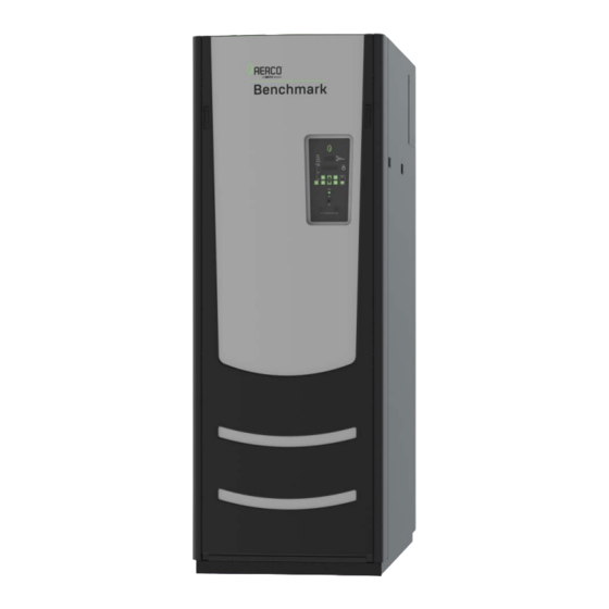
- Page 1 Operation and Maintenance Manual ® Benchmark Boilers Natural Gas, Propane Gas and Dual Fuel Fired Modulating & Condensing Boilers Models 750 through 3000 Other documents for this product include: OMM-0121, GF-205 Installation & Startup Manual TAG-0019, GF-2070 Boiler Application Guide TAG-0022, GF-2050 Vent-Combustion Air Guide TAG-0047, GF-2030 Benchmark Gas Guide TAG-0048, GF-2060 Benchmark Power Guide...
-
Page 2: Table Of Contents
Benchmark 750-3000 Boiler Operation & Maintenance Manual CONTENTS TABLE OF CONTENTS FOREWORD ...................... 5 SECTION 1: SAFETY PRECAUTIONS ..............9 1.1 WARNINGS & CAUTIONS ........................9 1.2 EMERGENCY SHUTDOWN ......................... 10 1.3 PROLONGED SHUTDOWN ......................... 10 1.4 IMPORTANT – FOR MASSACHUSETTS INSTALLATIONS ............... 11 SECTION 2: OPERATION ................. - Page 3 Benchmark 750-3000 Boiler Operation & Maintenance Manual CONTENTS 4.3 FLAME DETECTOR ..........................45 4.4 O SENSOR ............................45 4.5 SAFETY DEVICE TESTING ......................... 46 4.6 BURNER INSPECTION ........................46 4.6.1 BMK 750/1000 BURNER INSPECTION ......................47 4.6.2 BMK 1500 – 3000 BURNER INSPECTION ......................49 4.7 CONDENSATE DRAIN TRAP ......................
- Page 4 Benchmark 750-3000 Boiler Operation & Maintenance Manual CONTENTS (This page intentionally blank) OMM-0122_D • GF-206 • 5/9/2019 Technical Support • (800) 526-0288 • Mon-Fri, 8 am - 5 pm EST Page 4 of 164...
-
Page 5: Foreword
Benchmark 750-3000 Boiler Operation & Maintenance Manual FORWARD FOREWORD The AERCO Benchmark (BMK) 750, 1000, 1500, 2000, 2500, and 3000 natural gas and propane fueled boilers are modulating and condensing units. They represent a true industry advance that meets the needs of today's energy and environmental concerns. Designed for application in any closed loop hydronic system, the Benchmark's modulating capability relates energy input directly to fluctuating system loads. - Page 6 Benchmark 750-3000 Boiler Operation & Maintenance Manual FORWARD AERCO Technical Terminology Meanings TERMINOLOGY MEANING A (Amp) Ampere AERCO Control System, AERCO’s boiler management systems ADDR Address AGND Analog Ground ALRM Alarm ANSI American National Standards Institute, ASME American Society of Mechanical Engineers Auxiliary Building Automation System, often used interchangeably with EMS (see below)
- Page 7 Benchmark 750-3000 Boiler Operation & Maintenance Manual FORWARD AERCO Technical Terminology Meanings TERMINOLOGY MEANING Header Hexadecimal Number (0 – 9, A – F) Horse Power Heat Exchanger Hertz (Cycles Per Second) I.D. Inside Diameter Ignition IGST Board Ignition/Stepper Board, contained in the C-More Controller INTLK (INTL’K) Interlock Input/Output...
- Page 8 Benchmark 750-3000 Boiler Operation & Maintenance Manual FORWARD AERCO Technical Terminology Meanings TERMINOLOGY MEANING P&T Pressure and Temperature ProtoNode Hardware interface between BAS and a boiler or water heater Poly Vinyl Chloride, a common synthetic plastic Pulse Width Modulation REF (Ref) Reference RES.
-
Page 9: Section 1: Safety Precautions
Benchmark 750-3000 Boiler Operation & Maintenance Manual SECTION 1: SAFETY PRECAUTIONS SECTION 1: SAFETY PRECAUTIONS 1.1 WARNINGS & CAUTIONS Installers and operating personnel MUST, at all times, observe all safety regulations. The following warnings and cautions are general and must be given the same attention as specific precautions included in these instructions. -
Page 10: Emergency Shutdown
Benchmark 750-3000 Boiler Operation & Maintenance Manual SECTION 1: SAFETY PRECAUTIONS 1.2 EMERGENCY SHUTDOWN If overheating occurs or the gas supply fails to shut off, close the manual gas shutoff valve (Figure 1-1) located external to the unit. NOTE: The Installer must identify and indicate the location of the emergency shutdown manual gas valve to operating personnel. -
Page 11: Important - For Massachusetts Installations
Benchmark 750-3000 Boiler Operation & Maintenance Manual SECTION 1: SAFETY PRECAUTIONS 1.4 IMPORTANT – FOR MASSACHUSETTS INSTALLATIONS Requirements For Massachusetts Installations Boiler Installations within the Commonwealth of Massachusetts must conform to the following requirements: • Boiler must be installed by a plumber or a gas fitter who is licensed within the Commonwealth of Massachusetts. - Page 12 Benchmark 750-3000 Boiler Operation & Maintenance Manual SECTION 1: SAFETY PRECAUTIONS Requirements For Massachusetts Installations 4. INSPECTION: The state or local gas inspector of the side wall horizontally vented gas fueled equipment shall not approve the installation unless, upon inspection, the inspector observes carbon monoxide detectors and signage installed in accordance with the provisions of 248 CMR 5.08(2)(a)1 through 4.
-
Page 13: Section 2: Operation
Benchmark 750-3000 Boiler Operation & Maintenance Manual SECTION 2: OPERATION SECTION 2: OPERATION 2.1 INTRODUCTION The information in this section provides a guide to the operation of the Benchmark Boiler using the C-More Controller mounted on the front of the unit. It is imperative that the initial startup of this unit be performed by factory trained personnel. -
Page 14: C-More Controller Description
Benchmark 750-3000 Boiler Operation & Maintenance Manual SECTION 2: OPERATION 2.2 C-MORE CONTROLLER DESCRIPTION All Benchmark boilers utilize the C-More Controller shown in Figure 2-1. This panel contains all of the controls, indicators and displays necessary to operate, adjust and troubleshoot the boiler. These operating controls, indicators and displays are listed and described in Table 2-1. - Page 15 Benchmark 750-3000 Boiler Operation & Maintenance Manual SECTION 2: OPERATION TABLE 2-1: Controls, Indicators, And Displays (ref. Figure 2-1) CONTROL, INDICATOR ITEM FUNCTION or DISPLAY LED STATUS INDICATORS Four Status LEDs indicate the current operating status as follows: COMM = Lights when RS232 communication is occurring –...
- Page 16 Benchmark 750-3000 Boiler Operation & Maintenance Manual SECTION 2: OPERATION TABLE 2-1: Controls, Indicators, And Displays (ref. Figure 2-1) CONTROL, INDICATOR ITEM FUNCTION or DISPLAY MENU KEYPAD Six (6) keys which provide the following functions for the C-More Controller menus: Steps through the main menu categories shown in Figure 2-2.
-
Page 17: C-More Controller Menus
Benchmark 750-3000 Boiler Operation & Maintenance Manual SECTION 2: OPERATION 2.3 C-MORE CONTROLLER MENUS The C-More Controller incorporates an extensive menu structure which permits the operator to set up, and configure the unit. The menu structure consists of five major menu categories which are applicable to this manual. - Page 18 Benchmark 750-3000 Boiler Operation & Maintenance Manual SECTION 2: OPERATION * Only if BST is enabled. BST is described in detail in Section 6 of the Benchmark 750 – 3000 Installation and Startup Guide, OMM-0121 (GF-205). Figure 2-2: Menu Structure NOTE: The following sections provide brief descriptions of the options contained in each menu.
-
Page 19: Operating Menu
Benchmark 750-3000 Boiler Operation & Maintenance Manual SECTION 2: OPERATION 2.4 OPERATING Menu The Operating menu displays a number of key operating parameters for the unit. All items in this menu except O2 Monitor (item 15) are “Read-Only” and cannot be changed. This menu can be accessed without entering a password. -
Page 20: Setup Menu
Benchmark 750-3000 Boiler Operation & Maintenance Manual SECTION 2: OPERATION 2.5 SETUP Menu The Setup menu permits the operator to enter the unit password (159) which is required to change the menu options. To prevent unauthorized use, the password will time-out after 1 hour. Therefore, the correct password must be reentered when required. -
Page 21: Configuration Menu
Benchmark 750-3000 Boiler Operation & Maintenance Manual SECTION 2: OPERATION 2.6 CONFIGURATION Menu The Configuration menu permits adjustment of the Internal Setpoint (Setpt) temperature regardless of whether the valid password has been entered. Setpt is required for operation in the CONSTANT SETPOINT mode. The remaining options in this menu require the valid password to be entered, prior to changing existing entries. - Page 22 Benchmark 750-3000 Boiler Operation & Maintenance Manual SECTION 2: OPERATION TABLE 2-4: CONFIGURATION Menu AVAILABLE CHOICES OR LIMIT MENU ITEM DISPLAY DEFAULT Minimum Maximum Setpt Hi Limit Setpt Lo Limit 210°F (98.9°C) 180°F (82.2°C) Temp Hi Limit 40°F (4.4° 210°F (98.9° 195°F (90.6°...
-
Page 23: Tuning Menu
Benchmark 750-3000 Boiler Operation & Maintenance Manual SECTION 2: OPERATION 2.7 TUNING Menu The Tuning menu items are Factory set for each individual unit. Do not change these menu entries unless specifically requested to do so by factory-trained personnel. A full description of each item appears in Appendix A-4. TABLE 2-5: TUNING Menu MENU ITEM DISPLAY MINIMUM... -
Page 24: Bmk 1500/2000 Combustion Cal Menus
Benchmark 750-3000 Boiler Operation & Maintenance Manual SECTION 2: OPERATION 2.8.2 BMK 1500/2000 COMBUSTION CAL Menus TABLE 2-7a: COMBUSTION CAL Menu: BMK 1500/2000 SINGLE FUEL – NATURAL GAS DEFAULT MENU ITEM DISPLAY MINIMUM MAXIMUM BMK 1500 BMK 2000 CAL Voltage 16% 1.80 –... -
Page 25: Bmk 2500/3000 Combustion Cal Menus
Benchmark 750-3000 Boiler Operation & Maintenance Manual SECTION 2: OPERATION 2.8.3 BMK 2500/3000 COMBUSTION CAL Menus TABLE 2-8a: COMBUSTION CAL Menu: BMK 2500/3000 SINGLE FUEL – NATURAL GAS DEFAULT MENU ITEM DISPLAY MINIMUM MAXIMUM BMK 2500 BMK 3000 CAL Voltage 16% 2.20 –... -
Page 26: Bst (Boiler Sequencing Technology) Menu
Benchmark 750-3000 Boiler Operation & Maintenance Manual SECTION 2: OPERATION 2.9 BST (Boiler Sequencing Technology) Menu The BST menu must be enabled in order to be displayed and accessed. The BST Menu item, located at the end of the Configuration menu (item 37 in Table 2-4), must be set to Enabled. The BST menu contains all of the items required to configure, operate and monitor the functionality of the BST System. - Page 27 Benchmark 750-3000 Boiler Operation & Maintenance Manual SECTION 2: OPERATION TABLE 2-9: BST Menu AVAILABLE CHOICES OR LIMIT MENU ITEM DISPLAY DEFAULT Minimum Maximum Header Temp Addr Header Temp Point BST Outdoor Sens Disabled Enabled Disabled Outdr Tmp Source Outdoor Temp Network Outdoor Temp Outdoor Tmp Addr...
- Page 28 Benchmark 750-3000 Boiler Operation & Maintenance Manual SECTION 2: OPERATION TABLE 2-9: BST Menu AVAILABLE CHOICES OR LIMIT MENU ITEM DISPLAY DEFAULT Minimum Maximum BST Deadband Hi BST Deadband Lo Deadband En Time 120 Sec 30 Sec BST FR Up Rate BST Bldg Ref Tmp 40°F (4.4°C) 230°F (110°C)
-
Page 29: Calibration Menu
Benchmark 750-3000 Boiler Operation & Maintenance Manual SECTION 2: OPERATION 2.10 CALIBRATION MENU The Calibration menu is used by factory trained service personnel to adjust or reset the parameters listed below. A full description of each item appears in Appendix A-6. TABLE 2-10: CALIBRATION Menu AVAILABLE CHOICES OR LIMIT MENU ITEM DISPLAY... - Page 30 Benchmark 750-3000 Boiler Operation & Maintenance Manual SECTION 2: OPERATION TABLE 2-10: CALIBRATION Menu AVAILABLE CHOICES OR LIMIT MENU ITEM DISPLAY DEFAULT Minimum Maximum A/F Sensitivity Power Reset Automatic or Manual Automatic Water Temp Reset Automatic or Manual Automatic Gas Press Reset Automatic or Manual Manual Min Off Time...
-
Page 31: Section 3: Modes Of Operation
Benchmark 750-3000 Boiler Operation & Maintenance Manual SECTION 3 – MODES OF OPERATION SECTION 3: MODES OF OPERATION 3.1 INTRODUCTION The boiler is capable of being operated in any one of six different modes. The following sections provide descriptions of each of these operating modes. Each boiler is shipped from the factory tested and configured for the ordered mode of operation. -
Page 32: Indoor/Outdoor Startup
Benchmark 750-3000 Boiler Operation & Maintenance Manual SECTION 3 – MODES OF OPERATION 3.2.4 Indoor/Outdoor Startup Startup in the INDOOR/OUTDOOR RESET mode is accomplished as follows: NOTE: A design engineer typically provides design outdoor air temperature and supply header temperature data. Indoor / Outdoor Setup Instructions 1. -
Page 33: Setting The Setpoint
Benchmark 750-3000 Boiler Operation & Maintenance Manual SECTION 3 – MODES OF OPERATION 3.3.1 Setting the Setpoint The setpoint temperature of the unit is adjustable from 40°F to 240°F (4.4°C to 115.6°C). To set the unit for operation in the CONSTANT SETPOINT mode, you must set menu items Internal Setpt and Boiler Mode in the Configuration menu as follows: TABLE 3-1: Constant Setpoint Mode Settings MENU OPTION... -
Page 34: Remote Setpoint Field Wiring
Benchmark 750-3000 Boiler Operation & Maintenance Manual SECTION 3 – MODES OF OPERATION If the Network setting is selected for RS-485 Modbus operation, a valid Comm Address must be entered in the Setup menu. Refer to Modbus Communication Manual GF-114 for additional information. -
Page 35: Direct Drive Field Wiring
Benchmark 750-3000 Boiler Operation & Maintenance Manual SECTION 3 – MODES OF OPERATION NOTE: If a voltage, rather than current signal is used to control the remote setpoint, a DIP switch adjustment must be made on the CPU Board located in the C-More Controller. Contact your local AERCO representative for details. -
Page 36: Aerco Control System (Acs)
Benchmark 750-3000 Boiler Operation & Maintenance Manual SECTION 3 – MODES OF OPERATION 3.6 AERCO CONTROL SYSTEM (ACS) NOTE: ACS is for installations with 9 or more boilers. It utilizes only RS-485 signaling to the boiler. Installations with 1 to 8 boilers can use Boiler Sequencing Technology (BST), as described in Section 6 of the Benchmark 750 –... -
Page 37: Combination Control System (Ccs)
Benchmark 750-3000 Boiler Operation & Maintenance Manual SECTION 3 – MODES OF OPERATION 3.7 COMBINATION CONTROL SYSTEM (CCS) NOTE: Only ACS can be utilized for the Combination Control System. A Combination Control System (CCS) is one that uses multiple boilers to cover both space- heating and domestic hot water needs. -
Page 38: Combination Control System Field Wiring
Benchmark 750-3000 Boiler Operation & Maintenance Manual SECTION 3 – MODES OF OPERATION 3.7.1 Combination Control System Field Wiring Wiring for this system is between the ACS, the ACS Relay Box, and the terminals in the I/O Box. Wire the units using a shielded twisted pair of 18 to 22 AWG wire. When wiring multiple units, each unit’s wiring must conform to the above. -
Page 39: Section 4: Maintenance
Benchmark 750-3000 Boiler Operation & Maintenance Manual SECTION 4 – MAINTENANCE SECTION 4: MAINTENANCE 4.1 MAINTENANCE SCHEDULE All Benchmark boilers require regular routine maintenance to keep up efficiency and reliability. For best operation and life of the unit, the following routine maintenance procedures should be performed in the time periods specified in Table 4-1. -
Page 40: Igniter-Injector
Benchmark 750-3000 Boiler Operation & Maintenance Manual SECTION 4 – MAINTENANCE 4.2 IGNITER-INJECTOR The igniter-injector (Kit P/N 58023) is located on the burner plate at the top of the boiler. In addition to providing the ignition spark required to light the burner, the igniter-injector also contains a gas injector tube which connects to the staged ignition assembly. - Page 41 Benchmark 750-3000 Boiler Operation & Maintenance Manual SECTION 4 – MAINTENANCE BLOWER A/F VALVE BLOWER PLENUM PLENUM IGNITER- INJECTOR ASSEMBLY BLOCKED INLET SWITCH LEAN O SENSOR AIR/FUEL FLAME VALVE PLENUM FLANGE/ DETECTOR BURNER TOP PLATE FLAME BURNER OBSERVATION PORT Figure 4-1b: BMK 1500/2000 Burner Assembly (Removed from Boiler) BLOWER A/F VALVE BLOWER...
- Page 42 Benchmark 750-3000 Boiler Operation & Maintenance Manual SECTION 4 – MAINTENANCE The igniter-injector may be hot, therefore, care should be exercised to avoid burns. It is easier to remove the igniter-injector from the unit after the unit has cooled to room temperature. To inspect/replace the Igniter: Igniter-Injector Maintenance Procedure Instructions 1.
- Page 43 Benchmark 750-3000 Boiler Operation & Maintenance Manual SECTION 4 – MAINTENANCE Igniter-Injector Maintenance Procedure Instructions STAGED IGNITION COMPRESSION SOLENOID FITTING & ELBOW FLAME DETECTOR & BLOWER GASKET PLENUM O2 SENSOR FLEX GAS & WASHER HOSE NIPPLE FLAME OBSERVATION INJECTOR-IGNITOR PORT ASSY WITH INDEXING (CLOCKING) WASHERS BURNER PLATE...
- Page 44 Benchmark 750-3000 Boiler Operation & Maintenance Manual SECTION 4 – MAINTENANCE Igniter-Injector Maintenance Procedure Instructions BLOWER POSITION BURNER PLATE INJECTOR TUBE INSIDE THIS ARC INJECTOR TUBE IGNITER-INJECTOR Figure 4-3a: BMK 750/1000 Igniter-Injector Orientation POSITION INJECTOR TUBE INJECTOR TUBE INSIDE THIS ARC IGNITER-INJECTOR FLAME DETECTOR...
-
Page 45: Flame Detector
Benchmark 750-3000 Boiler Operation & Maintenance Manual SECTION 4 – MAINTENANCE 4.3 FLAME DETECTOR The flame detector (kit P/N 24356-1) is located on the burner plate at the top of the unit (see Figure 4-1a through 4-1c and 4-2a through 4-2c, above). The flame detector may be hot. Allow the unit to cool sufficiently before removing the flame detector. -
Page 46: Safety Device Testing
Benchmark 750-3000 Boiler Operation & Maintenance Manual SECTION 4 – MAINTENANCE 4.5 SAFETY DEVICE TESTING Systematic and thorough tests of the operating and safety devices should be performed to ensure that they are operating as designed. Certain code requirements, such as ASME CSD-1, require that these tests be performed on a scheduled basis. -
Page 47: Bmk 750/1000 Burner Inspection
Benchmark 750-3000 Boiler Operation & Maintenance Manual SECTION 4 – MAINTENANCE 4.6.1 BMK 750/1000 BURNER INSPECTION BMK 750/1000 Burner Inspection Instructions REAR FRONT BLOWER BURNER PLATE 3/16”–16 HEX NUTS (8) BLOWER PROOF SWITCH IGNITER-INJECTOR BLOCKED INLET STAGED IGNITION SWITCH ASSEMBLY 1/2"... - Page 48 Benchmark 750-3000 Boiler Operation & Maintenance Manual SECTION 4 – MAINTENANCE BMK 750/1000 Burner Inspection Instructions 3. Disconnect the lead wire from the flame detector installed on the burner plate. See Figure 4-4b. 4. Remove the two (2) screws securing the flame detector to the plate. The flame detector is secured to the burner plate with one (1) #10-32 screw and one (1) #8-32 screw.
-
Page 49: Bmk 1500 - 3000 Burner Inspection
Benchmark 750-3000 Boiler Operation & Maintenance Manual SECTION 4 – MAINTENANCE 4.6.2 BMK 1500 – 3000 BURNER INSPECTION BMK 1500-3000 Burner Inspection Instructions 5/16” x 1-3/4” BOLTS, IGNITER- BLOWER 5/16” WASHERS & INJECTOR PLENUM NYLOCK NUTS (4 each) ASSEMBLY 3/8”-16 BLOWER HEX NUTS BURNER PLATE... - Page 50 Benchmark 750-3000 Boiler Operation & Maintenance Manual SECTION 4 – MAINTENANCE BMK 1500-3000 Burner Inspection Instructions 5/16” x 1-3/4” BOLTS, BLOWER PLENUM 5/16” WASHERS & NYLOCK NUTS (4 each) IGNITER- BLOWER INJECTOR A/F VALVE ASSEMBLY PLENUM AIR/FUEL BURNER VALVE FILTER PLATE 1/2”...
- Page 51 Benchmark 750-3000 Boiler Operation & Maintenance Manual SECTION 4 – MAINTENANCE BMK 1500-3000 Burner Inspection Instructions 1. Set the ON/OFF switch on the C-More Controller to the OFF position. Disconnect AC power from the unit and turn off the gas supply. 2.
- Page 52 Benchmark 750-3000 Boiler Operation & Maintenance Manual SECTION 4 – MAINTENANCE BMK 1500-3000 Burner Inspection Instructions IMPORTANT! NOTE: Use ALL THREE gaskets provided, even if there The LOWER RELEASE GASKET (P/N 81186) features four tabs around its periphery. is only one existing gasket being replaced. 81183 –...
-
Page 53: Condensate Drain Trap
Benchmark 750-3000 Boiler Operation & Maintenance Manual SECTION 4 – MAINTENANCE 4.7 CONDENSATE DRAIN TRAP Benchmark boilers contain a condensate trap (P/N 24441), located external to the unit and attached to the drain connection from the exhaust manifold at the rear of the unit (shown in Figure 2-6a and 2-6b of the Benchmark 750 –... -
Page 54: Air Filter Cleaning And Replacement
Benchmark 750-3000 Boiler Operation & Maintenance Manual SECTION 4 – MAINTENANCE 4.8 AIR FILTER CLEANING and REPLACEMENT The Benchmark boiler is equipped with an air filter which should be cleaned and re-oiled every 12 months and replaced every 24 months. The air filter is located at the air fuel valve inlet, as shown in Figure 4-8. -
Page 55: Water Cutoff (Lwco) Capacitor Integrity Test
Benchmark 750-3000 Boiler Operation & Maintenance Manual SECTION 4 – MAINTENANCE Air Filter Cleaning and Replacement Instructions 5. The filter may be cleaned in hot soapy water to remove oil and dirt. It should then be thoroughly dried and then sprayed with a light coating of K&N® Air Filter Oil (or equivalent specifically formulated for air filters) prior to reinstallation. -
Page 56: Low Water Cutoff (Lwco) - Capacitor Electrical Short Test
Benchmark 750-3000 Boiler Operation & Maintenance Manual SECTION 4 – MAINTENANCE 4.9.1 Low Water Cutoff (LWCO) - Capacitor Electrical Short Test This test determines if there is an electrical short between the LWCO capacitor and the heat exchanger. Perform the capacitor electrical short test as described below. Low Water Cutoff –... -
Page 57: Low Water Cutoff (Lwco) - Standard C-More Test
Benchmark 750-3000 Boiler Operation & Maintenance Manual SECTION 4 – MAINTENANCE 4.9.2 Low Water Cutoff (LWCO) - Standard C-More Test Perform the standard Low Water Cutoff test using the C-More Controller as described below. Low Water Cutoff (LWCO) - Standard C-More Test Instructions 1. -
Page 58: Placing The Boiler Back In Service After Aprolonged Shutdown
Benchmark 750-3000 Boiler Operation & Maintenance Manual SECTION 4 – MAINTENANCE 4.11 PLACING THE BOILER BACK IN SERVICE AFTER A PROLONGED SHUTDOWN After a prolonged shutdown (one year or more), the following procedures must be followed: Placing The Boiler Back In Service After A Prolonged Shutdown Instructions 1. -
Page 59: Section 5: Troubleshooting Guide
Benchmark 750-3000 Boiler Operation & Maintenance Manual SECTION 5 – TROUBLESHOOTING GUIDE SECTION 5: TROUBLESHOOTING GUIDE 5.1 INTRODUCTION This troubleshooting guide is intended to aid service/maintenance personnel in isolating the cause of a fault in Benchmark 750 through 3000 boilers. The troubleshooting procedures contained herein are presented in tabular form on the following pages. - Page 60 Benchmark 750-3000 Boiler Operation & Maintenance Manual SECTION 5 – TROUBLESHOOTING GUIDE (This page intentionally blank) OMM-0122_D • GF-206 • 5/9/2019 Technical Support • (800) 526-0288 • Mon-Fri, 8 am - 5 pm EST Page 60 of 164...
- Page 61 Benchmark 750-3000 Boiler Operation & Maintenance Manual SECTION 5 – TROUBLESHOOTING GUIDE TABLE 5-1: Boiler Troubleshooting Procedures Fault Probable Causes Corrective Action Indication Blower stopped running due to thermal or Check combustion blower for signs of excessive heat or high current current overload.
- Page 62 Benchmark 750-3000 Boiler Operation & Maintenance Manual SECTION 5 – TROUBLESHOOTING GUIDE TABLE 5-1: Boiler Troubleshooting Procedures Fault Probable Causes Corrective Action Indication Blower not running or running too slow. Start the unit. If the blower does not run check the blower solid state relay for input and output voltage.
- Page 63 Benchmark 750-3000 Boiler Operation & Maintenance Manual SECTION 5 – TROUBLESHOOTING GUIDE TABLE 5-1: Boiler Troubleshooting Procedures Fault Probable Causes Corrective Action Indication Delayed Interlock Jumper not properly installed Check to insure jumper is properly installed across the delayed or missing. interlock terminals in the I/O Box.
- Page 64 Benchmark 750-3000 Boiler Operation & Maintenance Manual SECTION 5 – TROUBLESHOOTING GUIDE TABLE 5-1: Boiler Troubleshooting Procedures Fault Probable Causes Corrective Action Indication Worn Flame Detector or cracked ceramic. Remove and inspect the Flame Detector for signs of wear or cracked ceramic.
- Page 65 Benchmark 750-3000 Boiler Operation & Maintenance Manual SECTION 5 – TROUBLESHOOTING GUIDE TABLE 5-1: Boiler Troubleshooting Procedures Fault Probable Causes Corrective Action Indication Faulty Water temperature switch. Test the temperature switch to insure it trips at its actual water temperature setting. Incorrect PID settings.
- Page 66 Benchmark 750-3000 Boiler Operation & Maintenance Manual SECTION 5 – TROUBLESHOOTING GUIDE TABLE 5-1: Boiler Troubleshooting Procedures Fault Probable Causes Corrective Action Indication Air/Fuel Valve not rotating. Start the unit. The Air/Fuel Valve should rotate to the purge (open) position. If the valve does not rotate at all or does not rotate fully open, check the Air/Fuel Valve calibration.
- Page 67 Benchmark 750-3000 Boiler Operation & Maintenance Manual SECTION 5 – TROUBLESHOOTING GUIDE TABLE 5-1: Boiler Troubleshooting Procedures Fault Probable Causes Corrective Action Indication Interlock jumper not installed or removed. Check for a jumper properly installed across the interlock terminals in the I/O box. If there are two external wires on these terminals check any Energy Energy Management System does not have unit Management system to see if they have the units disabled (a jumper...
- Page 68 Benchmark 750-3000 Boiler Operation & Maintenance Manual SECTION 5 – TROUBLESHOOTING GUIDE TABLE 5-1: Boiler Troubleshooting Procedures Fault Probable Causes Corrective Action Indication A/F Valve rotated open to purge and did not Start the unit. The Air/Fuel Valve should rotate to the purge (open) rotate to ignition position.
- Page 69 Benchmark 750-3000 Boiler Operation & Maintenance Manual SECTION 5 – TROUBLESHOOTING GUIDE TABLE 5-1: Boiler Troubleshooting Procedures Fault Probable Causes Corrective Action Indication Combustion Calibration incorrect. Check Combustion Analyzer and recalibrate the boiler. O2 % OUT OF Blocked inlet air duct or louver. Unblock air inlet and measure open area for combustion air to the RANGE room.
- Page 70 Benchmark 750-3000 Boiler Operation & Maintenance Manual SECTION 5 – TROUBLESHOOTING GUIDE TABLE 5-1: Boiler Troubleshooting Procedures Fault Probable Causes Corrective Action Indication SSOV relay failed on IGST board. Press CLEAR button and restart unit. If fault persists, replace Ignition/Stepper (IGST) Board. Floating Neutral.
-
Page 71: Additional Faults Without Specific Fault Messages
Benchmark 750-3000 Boiler Operation & Maintenance Manual SECTION 5 – TROUBLESHOOTING GUIDE 5.2 ADDITIONAL FAULTS WITHOUT SPECIFIC FAULT MESSAGES Refer to Table 5-2 to troubleshoot faults which may occur without a specific fault message being displayed. TABLE 5-2: Boiler Troubleshooting With No Fault Message Displayed Observed Incident Probable Causes Corrective Action... - Page 72 Benchmark 750-3000 Boiler Operation & Maintenance Manual SECTION 5 – TROUBLESHOOTING GUIDE DAMPING ORIFICE BRASS HEX HEAD (Remove to access the Gas Pressure Adjustment Screw). COVER SCREW Figure 5-1: SSOV Actuator With Gas Pressure Adjustment (SKP25) OMM-0122_D • GF-206 • 5/9/2019 Technical Support •...
-
Page 73: Appendix A: Boiler Menu Item Descriptions
Benchmark 750-3000 Boiler Operation & Maintenance Manual APPENDIX A: BOILER MENU DESCRIPTIONS Appendix A: BOILER MENU ITEM DESCRIPTIONS TABLE A-1: OPERATING MENU ITEM DESCRIPTIONS See section 2-4 OPERATING Menu for a range of choices and the default values. TABLE A-1: OPERATING Menu Item Descriptions MENU OPTIONS DESCRIPTION This is the setpoint temperature to which the control is set... - Page 74 Benchmark 750-3000 Boiler Operation & Maintenance Manual APPENDIX A: BOILER MENU DESCRIPTIONS An additional parameter associated with the Operating menu, Manual Valve Pos (Min = 0, Max = 100) does not appear in this menu, but can be displayed by pushing the Auto/Man button on the C-More Controller’s front face.
- Page 75 Benchmark 750-3000 Boiler Operation & Maintenance Manual APPENDIX A: BOILER MENU DESCRIPTIONS TABLE A-2: SETUP MENU ITEM DESCRIPTIONS See section 2-5 SETUP Menu for a range of choices and the default values. TABLE A-2: SETUP Menu Item Descriptions MENU OPTIONS DESCRIPTION Allows Level 1 or Level 2 password to be entered.
- Page 76 Benchmark 750-3000 Boiler Operation & Maintenance Manual APPENDIX A: BOILER MENU DESCRIPTIONS TABLE A-3: CONFIGURATION MENU ITEM DESCRIPTIONS See section 2-6 CONFIGURATION Menu for a range of choices and the default values. The Configuration menu settings are Factory-Set in accordance with the requirements specified with each individual order.
- Page 77 Benchmark 750-3000 Boiler Operation & Maintenance Manual APPENDIX A: BOILER MENU DESCRIPTIONS TABLE A-3: CONFIGURATION Menu Item Descriptions MENU OPTIONS DESCRIPTION Specifies the amount of time to wait, up to 120 seconds, Aux Start On Dly between activating the Aux Relay (due to a demand) and checking the pre-purge string to start the boiler.
- Page 78 Benchmark 750-3000 Boiler Operation & Maintenance Manual APPENDIX A: BOILER MENU DESCRIPTIONS TABLE A-3: CONFIGURATION Menu Item Descriptions MENU OPTIONS DESCRIPTION Deadband High and Deadband Low settings create an “Outlet Temperature” Zone in which no Valve Position corrections will be attempted. The Deadband ZONE is defined as operating with an Outlet Temperature between Active Setpoint + Deadband High and Active Setpoint –...
- Page 79 Benchmark 750-3000 Boiler Operation & Maintenance Manual APPENDIX A: BOILER MENU DESCRIPTIONS TABLE A-4: TUNING MENU ITEM DESCRIPTIONS See section 2-7 TUNING Menu for a range of choices and the default values. TABLE A-4: TUNING Menu Item Descriptions MENU OPTIONS DESCRIPTION Generates a fire rate based on the error that exists between the setpoint temperature and the actual outlet temperature.
- Page 80 Benchmark 750-3000 Boiler Operation & Maintenance Manual APPENDIX A: BOILER MENU DESCRIPTIONS TABLE A-5: COMBUSTION CALIBRATION MENU ITEM DESCRIPTIONS See section 2-8 COMBUSTION CAL Menu for a range of choices and the default values. NOTE: The Level 2 Password must be entered to view the options in the Combustion Cal menu. This Menu is used during the Combustion Calibration procedures described in Section 4.4 of the Benchmark 750 –...
- Page 81 Benchmark 750-3000 Boiler Operation & Maintenance Manual APPENDIX A: BOILER MENU DESCRIPTIONS TABLE A-6: CALIBRATION MENU ITEM DESCRIPTIONS See section 2-10 CALIBRATION Menu for a range of choices and the default values. TABLE A-6: CALIBRATION Menu Item Descriptions MENU OPTION DESCRIPTION Allows the Air/Fuel Valve stepper motor feedback current to be calibrated at Stepper Fbk...
- Page 82 Benchmark 750-3000 Boiler Operation & Maintenance Manual APPENDIX A: BOILER MENU DESCRIPTIONS TABLE A-6: CALIBRATION Menu Item Descriptions MENU OPTION DESCRIPTION Supply Gas Pressure Allows adjustment of the Supply Gas Pressure level from In Adj -5.0% to +5.0% in 0.1 % increments. Allows adjustment of the Gas Plate dp level from -5.0% to +5.0% in 0.1% Gas Plate dp In Adj increments.
- Page 83 Benchmark 750-3000 Boiler Operation & Maintenance Manual APPENDIX A: BOILER MENU DESCRIPTIONS TABLE A-6: CALIBRATION Menu Item Descriptions MENU OPTION DESCRIPTION – Outdr Air Offset Range: -20 to + 20 (either ºF or °C) – Inlet Air Offset Range: -20 to + 20 (either ºF or °C) –...
- Page 84 Benchmark 750-3000 Boiler Operation & Maintenance Manual APPENDIX A: BOILER MENU DESCRIPTIONS (This page intentionally blank) OMM-0122_D • GF-206 • 5/9/2019 Technical Support • (800) 526-0288 • Mon-Fri, 8 am - 5 pm EST Page 84 of 164...
-
Page 85: Appendix B: Startup, Status, & Fault Messages
Benchmark 750-3000 Boiler Operation & Maintenance Manual APPENDIX B – STARTUP, STATUS, AND FAULT MESSAGES Appendix B: STARTUP, STATUS, & FAULT MESSAGES TABLE B-1: STARTUP AND STATUS MESSAGES TABLE B-1: Startup and Status Messages MESSAGE DESCRIPTION DEMAND DELAY Displayed if Demand Delay is active. XX sec DISABLED Displayed if ON/OFF switch is set to OFF. - Page 86 Benchmark 750-3000 Boiler Operation & Maintenance Manual APPENDIX B – STARTUP, STATUS, AND FAULT MESSAGES TABLE B-2: FAULT MESSAGES TABLE B-2: Fault Messages FAULT MESSAGE FAULT DESCRIPTION AIRFLOW FAULT The Blower Proof switch opened during purge, or air inlet is blocked. DURING PURGE AIRFLOW FAULT The Blower Proof switch opened during ignition.
- Page 87 Benchmark 750-3000 Boiler Operation & Maintenance Manual APPENDIX B – STARTUP, STATUS, AND FAULT MESSAGES TABLE B-2: Fault Messages FAULT MESSAGE FAULT DESCRIPTION NETWORK COMM The RS-485 network information is not present or is corrupted. FAULT % OUT OF RANGE % has gone below 3% or above 8%.
- Page 88 Benchmark 750-3000 Boiler Operation & Maintenance Manual APPENDIX B – STARTUP, STATUS, AND FAULT MESSAGES (This page intentionally blank) OMM-0122_D • GF-206 • 5/9/2019 Technical Support • (800) 526-0288 • Mon-Fri, 8 am - 5 pm EST Page 88 of 164...
-
Page 89: Appendix C: Sensor Resistance/Voltage Chart
Benchmark 750-3000 Boiler Operation & Maintenance Manual APPENDIX C – SENSOR RESISTANCE/VOLTAGE CHART Appendix C: SENSOR RESISTANCE/VOLTAGE CHART Temperature Sensor Resistance Voltage Chart (BALCO) TEMPERATURE RES (OHMS) VOLTS* °F °C 779.0 1.93 -34.4 797.5 1.96 -28.9 816.3 1.99 -23.3 835.4 2.02 -17.2 854.8... - Page 90 Benchmark 750-3000 Boiler Operation & Maintenance Manual APPENDIX C – SENSOR RESISTANCE/VOLTAGE CHART (This page intentionally blank) OMM-0122_D • GF-206 • 5/9/2019 Technical Support • (800) 526-0288 • Mon-Fri, 8 am - 5 pm EST Page 90 of 164...
-
Page 91: Appendix D: Recommended Periodic Testing
Benchmark 750-3000 Boiler Operation & Maintenance Manual APPENDIX D – RECOMMENDED PERIODIC TESTING Appendix D: RECOMMENDED PERIODIC TESTING WARNING! Periodic testing of all boiler controls and safety devices is required to determine that they are operating as designed. Precautions shall be taken while tests are being performed to protect against bodily injury and property damage. - Page 92 Benchmark 750-3000 Boiler Operation & Maintenance Manual APPENDIX D – RECOMMENDED PERIODIC TESTING Recommended Periodic Testing ITEM FREQUENCY ACTION BY REMARKS Operating controls Annually Operator See section 2.2. See section 5.8 in the Benchmark 750 – 3000 Low air flow Monthly Operator Installation and Startup Guide, OMM-0121...
-
Page 93: Appendix E: Indoor/Outdoor Reset Ratio Charts
Benchmark 750-3000 Boiler Operation & Maintenance Manual APPENDIX E: INDOOR/OUTDOOR RESET RATIO CHARTS Appendix E: INDOOR/OUTDOOR RESET RATIO CHARTS Header Temperature for a Building Reference Temperature = 50°F (10.0°C) AIR TEMP RESET RATIO °F °C 10.0 -1.1 -3.9 -6.7 -9.4 -12.2 -15.0 -17.8... - Page 94 Benchmark 750-3000 Boiler Operation & Maintenance Manual APPENDIX E: INDOOR/OUTDOOR RESET RATIO CHARTS Header Temperature for a Building Reference Temperature = 65°F (18.3°C) AIR TEMP RESET RATIO °F °C 18.3 15.6 12.8 10.0 -1.1 -3.9 -6.7 -9.4 -12.2 -15.0 -17.8 -20.6 -23.3 -26.1...
- Page 95 Benchmark 750-3000 Boiler Operation & Maintenance Manual APPENDIX E: INDOOR/OUTDOOR RESET RATIO CHARTS Header Temperature for a Building Reference Temperature = 75°F (23.9°C) AIR TEMP RESET RATIO °F °C 23.9 21.1 18.3 15.6 12.8 10.0 -1.1 -3.9 -6.7 -9.4 -12.2 -15.0 -17.8 -20.6...
- Page 96 Benchmark 750-3000 Boiler Operation & Maintenance Manual APPENDIX E: INDOOR/OUTDOOR RESET RATIO CHARTS Header Temperature for a Building Reference Temperature = 90°F (32.2°C) AIR TEMP RESET RATIO °F °C 32.2 29.4 26.7 23.9 21.1 18.3 15.6 12.8 10.0 -1.1 -3.9 -6.7 -9.4 -12.2...
-
Page 97: Appendix F: Benchmark 750/1000 Part List
Benchmark 750-3000 Boiler Operation & Maintenance Manual APPENDIX F – BENCHMARK 750/1000 PART LIST Appendix F: BENCHMARK 750/1000 PART LIST Benchmark 750 and Benchmark 1000 Part List Item # Qty Part # Description TERMINAL BLOCK: DIN MOUNTED: 65121 EXHAUST MANIFOLD TERMINAL GROUND BLOCK: DIN 65122 43086... - Page 98 Description 30 PSI 50 PSI 75 PSI 100 PSI 150 PSI 60 PSI 125 PSI 160 PSI Number Apollo Conbraco Apollo Watts Watts Watts Watts Kunkle 24286 6” Exhaust Kit 24441 Condensate Trap Assy. 92006-5 1” Ball Valve 123675-2 Tridicator...
- Page 99 Benchmark 750-3000 Boiler Operation & Maintenance Manual APPENDIX F – BENCHMARK 750/1000 PART LIST Benchmark 750/1000 Gas Trains FM Gas Train 22140-1 Propane Gas Train 22140-3 DBB Gas Train 22140-2 LEFT-REAR VIEW FRONT VIEW RIGHT-REAR VIEW Benchmark 750/1000 Part List 09/28/2017 AERCO International, Inc.
- Page 100 Benchmark 750-3000 Boiler Operation & Maintenance Manual APPENDIX F – BENCHMARK 750/1000 PART LIST Benchmark 750/1000 Burner – Air/Fuel Valve Assembly P/N 24276-TAB Full Diagram Below Benchmark 750/1000 Part List 09/28/2017 AERCO International, Inc. Blauvelt, NY BMK 750 28321-TAB rev F 10913 Sheet 4 of 6 BMK 1000 28253-TAB rev F...
- Page 101 Benchmark 750-3000 Boiler Operation & Maintenance Manual APPENDIX F – BENCHMARK 750/1000 PART LIST Benchmark 750/1000 Part List 09/28/2017 AERCO International, Inc. Blauvelt, NY BMK 750 28321-TAB rev F 10913 Sheet 5 of 6 BMK 1000 28253-TAB rev F OMM-0122_D • GF-206 • 5/9/2019 Technical Support •...
- Page 102 Benchmark 750-3000 Boiler Operation & Maintenance Manual APPENDIX F – BENCHMARK 750/1000 PART LIST TOP VIEW REAR VIEW LEFT SIDE VIEW FRONT VIEW RIGHT SIDE VIEW Benchmark 750/1000 Part List 09/28/2017 AERCO International, Inc. Blauvelt, NY BMK 750 28321-TAB rev F 10913 Sheet 6 of 6 BMK 1000 28253-TAB rev F...
- Page 103 Benchmark 750-3000 Boiler Operation & Maintenance Manual APPENDIX F – BENCHMARK 750/1000 PART LIST Benchmark 750/1000 FM Gas Train – P/N 22140-1 Item Qty Part # Description Item Part # Description 95026 1.25"NPT 125#: THREADED FLANGE 92006-5 VALVE: BALL 1" NPT 92036 VALVE: SSOV 1"...
- Page 104 Benchmark 750-3000 Boiler Operation & Maintenance Manual APPENDIX F – BENCHMARK 750/1000 PART LIST Benchmark 750/1000 DBB Gas Train – P/N 22140-2 Item Qty Part # Description Item Part # Description 95026 1.25" NPT 125#: THREADED FLANGE 92006-5 VALVE: BALL 1" NPT 92036 VALVE: SSOV 1"...
- Page 105 Benchmark 750-3000 Boiler Operation & Maintenance Manual APPENDIX F – BENCHMARK 750/1000 PART LIST BMK 750/1000 PROPANE Gas Train – P/N 22140-3 Item Qty Part # Description Item Qty Part # Description 95026 THREADED FLANGE: 1.25" NPT 125# 92006-3 VALVE: FULL PORT BALL 1/2" NPT BRASS 92103 VALVE: SSOV 1/2"...
- Page 106 Benchmark 750-3000 Boiler Operation & Maintenance Manual APPENDIX F – BENCHMARK 750/1000 PART LIST Benchmark 750/1000 Burner, Blower, Air/Fuel Valve Assy. – P/N 24276-TAB Item Qty Part # Description Item Part # Description 42140 PLATE: BURNER 46026 BURNER: BMK 1.0 81143 GASKET: BURNER 24367-1...
-
Page 107: Appendix G: Benchmark 1500/2000 Part List
Benchmark 750-3000 Boiler Operation & Maintenance Manual APPENDIX G – BENCHMARK 1500/2000 PART LIST Appendix G: BENCHMARK 1500/2000 PART LIST Benchmark 1500/1500DF & Benchmark 2000/2000DF Part List Item # Qty Part # Description 65121 TERMINAL BLOCK: DIN MOUNTED: WHT TERMINAL GROUND BLOCK: DIN EXHAUST MANIFOLD 65122 MOUNTED... - Page 108 58088-C150 150 PSI (1034 kPa) KIT (CONBRACO) 92023-7 123675-7 58087-7 125 PSI (862 kPa) 123620-W125 123675-6 58088-W30 30 PSI (207 kPa) KIT (WATTS) 92023-8 123675-5 58087-8 160 PSI (1103 kPa) 123620-K160 123675-7 58088-W50 50 PSI (345 kPa) KIT (WATTS) 92023-9...
- Page 109 Benchmark 750-3000 Boiler Operation & Maintenance Manual APPENDIX G – BENCHMARK 1500/2000 PART LIST Benchmark 1500/1500DF, 2000/2000DF Part List 10/02/2017 AERCO International, Inc. Benchmark 1500 29313-TAB rev G Blauvelt, NY 10913 Sheet 3 of 9 Benchmark 2000 29337-TAB rev G OMM-0122_D •...
- Page 110 Benchmark 750-3000 Boiler Operation & Maintenance Manual APPENDIX G – BENCHMARK 1500/2000 PART LIST Benchmark 1500/2000 Burner-Air/Fuel Valve Assembly P/N 24378, 24378-1 & 24378-2 Full part lists below Benchmark 1500/1500DF, 2000/2000DF Part List 10/02/2017 AERCO International, Inc. Benchmark 1500 29313-TAB rev G Blauvelt, NY 10913 Sheet 4 of 9 Benchmark 2000 29337-TAB rev G...
- Page 111 Benchmark 750-3000 Boiler Operation & Maintenance Manual APPENDIX G – BENCHMARK 1500/2000 PART LIST Benchmark 1500/2000 Benchmark 1500/2000 Standard FM Gas Train Double Block & Bleed Gas Train P/N 22188 P/N 22199 See full part lists below See full part lists below Benchmark 1500/1500DF, 2000/2000DF Part List 10/02/2017 AERCO...
- Page 112 Benchmark 750-3000 Boiler Operation & Maintenance Manual APPENDIX G – BENCHMARK 1500/2000 PART LIST Benchmark 1500DF/2000DF DUAL FUEL Gas Train P/N 22198 consists of: • 22188-1 NATURAL GAS gas train • 22197 PROPANE train Full gas train part lists are shown below NATURAL GAS Gas Train P/N 22188-1...
- Page 113 Benchmark 750-3000 Boiler Operation & Maintenance Manual APPENDIX G – BENCHMARK 1500/2000 PART LIST Benchmark 1500DF/2000DF DUAL FUEL Gas Train P/N 22201 consists of: • 22199-1 NATURAL GAS gas train • 22200 PROPANE train Full gas train part lists are shown below NATURAL GAS Gas Train P/N 22199-1...
- Page 114 Benchmark 750-3000 Boiler Operation & Maintenance Manual APPENDIX G – BENCHMARK 1500/2000 PART LIST REAR VIEW TOP VIEW FRONT VIEW LEFT SIDE VIEW Benchmark 1500/1500DF, 2000/2000DF Part List 10/02/2017 AERCO International, Inc. Benchmark 1500 29313-TAB rev G Blauvelt, NY 10913 Sheet 8 of 9 Benchmark 2000 29337-TAB rev G OMM-0122_D •...
- Page 115 Benchmark 750-3000 Boiler Operation & Maintenance Manual APPENDIX G – BENCHMARK 1500/2000 PART LIST PARTIAL FRONT VIEW Benchmark 1500/1500DF, 2000/2000DF Part List 10/02/2017 AERCO International, Inc. Benchmark 1500 29313-TAB rev G Blauvelt, NY 10913 Sheet 9 of 9 Benchmark 2000 29337-TAB rev G OMM-0122_D •...
- Page 116 Benchmark 750-3000 Boiler Operation & Maintenance Manual APPENDIX G – BENCHMARK 1500/2000 PART LIST Benchmark 1500-2000 Natural Gas Standard Gas Train – P/N 22188 Item Qty Part # Description Item Qty Part # Description 123542 FLANGE 2" 125# 2"NPT 97087-20 FLEX HOSE, 20"...
- Page 117 Benchmark 750-3000 Boiler Operation & Maintenance Manual APPENDIX G – BENCHMARK 1500/2000 PART LIST Benchmark 1500-2000 Natural Gas DBB Gas Train – P/N 22199 Item Qty Part No Description Item Qty Part No Description 123542 FLANGE 2" 125# 2" NPT 124094 UNION, 3/4"...
- Page 118 Benchmark 750-3000 Boiler Operation & Maintenance Manual APPENDIX G – BENCHMARK 1500/2000 PART LIST Benchmark 1500DF – 2000DF NATURAL GAS Gas Train – P/N 22188-1 Item Qty. Part No. Description Item Qty. Part No. Description 123542 FLANGE 2" 125# 2" NPT 93382 2'' NPT CAP 64048...
- Page 119 Benchmark 750-3000 Boiler Operation & Maintenance Manual APPENDIX G – BENCHMARK 1500/2000 PART LIST Benchmark 1500DF – 2000DF PROPANE Gas Train – P/N 22197 Item Qty. Part No. Description Item Qty. Part No. Description 92036 VALVE, SSOV 1" NPT 99017 SNUBBER, PRESSURE, 1/4"...
- Page 120 Benchmark 750-3000 Boiler Operation & Maintenance Manual APPENDIX G – BENCHMARK 1500/2000 PART LIST Benchmark 1500DF – 2000DF DBB NATURAL GAS Train – P/N 22199-1 Item Qty Part No. Description Item Qty Part No. Description 123542 FLANGE 2" 125# 2" NPT 9-291 UNION, 1"...
- Page 121 Benchmark 750-3000 Boiler Operation & Maintenance Manual APPENDIX G – BENCHMARK 1500/2000 PART LIST Benchmark 1500DF – 2000DF DBB PROPANE Gas Train – P/N 22200 Item Qty Part # Description Item Qty Part # Description 64048 ACTUATOR, SSOV W/ REGULATOR 92036 VALVE, SSOV 1"...
- Page 122 Benchmark 750-3000 Boiler Operation & Maintenance Manual APPENDIX G – BENCHMARK 1500/2000 PART LIST Benchmark 1500/2000 Burner Assembly – P/N 24378-TAB Item Part # Description Item Part # Description 58038 BLOWER: AMETEK 12.3" – Replacement Kit 81166 BURNER GASKET 43090 AIR FUEL VALVE PLENUM 58023 IGNITOR-INJECTOR –...
-
Page 123: Appendix H: Benchmark 2500/3000 Part List
Benchmark 750-3000 Boiler Operation & Maintenance Manual APPENDIX H: BENCHMARK 2500/3000 PART LIST Appendix H: BENCHMARK 2500/3000 PART LIST Benchmark 2500/2500 DF & Benchmark 3000/3000 DF Part List Item # Qty Part # Description 93230 SNUBBER - AIR/FUEL VALVE 64081 ECU, O SENSOR EXHAUST MANIFOLD... - Page 124 125 PSI (862 kPa) KIT (CONBRACO) 92016-6 123675-6 58048-C150 150 PSI (1034 kPa) KIT (CONBRACO) 92016-7 123675-7 24441 123540 58048-W50 50 PSI (345 kPa) KIT (WATTS) 92016-8 123675-5 58048-W60 60 PSI (414 kPa) KIT (WATTS) 92016-9 123675-6 58048-W75 75 PSI (517 kPa) KIT (WATTS) 92016-10...
- Page 125 Benchmark 750-3000 Boiler Operation & Maintenance Manual APPENDIX H – BENCHMARK 2500/3000 PART LIST Benchmark 2500/2500DF & 3000/3000DF Part List 10/09/2017 AERCO International, Inc. Blauvelt, NY Benchmark 2500 28536-TAB rev E 10913 Sheet 3 of 9 Benchmark 3000 28382-TAB rev F OMM-0122_D •...
- Page 126 Benchmark 750-3000 Boiler Operation & Maintenance Manual APPENDIX H – BENCHMARK 2500/3000 PART LIST Benchmark 2500/3000 Burner - Air/Fuel Valve Assembly P/N 26015-TAB & 26014-TAB Full part lists below Benchmark 2500/2500DF & 3000/3000DF Part List 10/09/2017 AERCO International, Inc. Blauvelt, NY Benchmark 2500 28536-TAB rev E 10913 Sheet 4 of 9...
- Page 127 Benchmark 750-3000 Boiler Operation & Maintenance Manual APPENDIX H – BENCHMARK 2500/3000 PART LIST Benchmark 3000 Benchmark 3000 Standard FM Gas Train Double Block & Bleed Gas Train P/N 22171 P/N 22173 See full drawing below See full drawing below Benchmark 2500 Benchmark 2500 Standard FM Gas Train...
- Page 128 Benchmark 750-3000 Boiler Operation & Maintenance Manual APPENDIX H – BENCHMARK 2500/3000 PART LIST NATURAL PROPANE INLET INLET NATURAL PROPANE INLET INLET Natural Gas Natural Gas P/N 22177 P/N 22177-1 Propane Propane P/N 22178 P/N 22178-1 Benchmark 3000 Dual Fuel Benchmark 3000 Dual Fuel FM Gas Train Double Block &...
- Page 129 Benchmark 750-3000 Boiler Operation & Maintenance Manual APPENDIX H – BENCHMARK 2500/3000 PART LIST NATURAL NATURAL PROPANE INLET PROPANE INLET INLET INLET Natural Gas Natural Gas P/N 22209-1 P/N 22210-1 Propane Propane P/N 22209-2 P/N 22210-2 Benchmark 2500 Dual Fuel Benchmark 2500 Dual Fuel FM Gas Train Double Block &...
- Page 130 Benchmark 750-3000 Boiler Operation & Maintenance Manual APPENDIX H – BENCHMARK 2500/3000 PART LIST REAR VIEW TOP VIEW LEFT SIDE VIEW FRONT VIEW Benchmark 2500/2500DF & 3000/3000DF Part List 10/09/2017 AERCO International, Inc. Blauvelt, NY Benchmark 2500 28536-TAB rev E 10913 Sheet 8 of 9 Benchmark 3000 28382-TAB rev F...
- Page 131 Benchmark 750-3000 Boiler Operation & Maintenance Manual APPENDIX H – BENCHMARK 2500/3000 PART LIST PARTIAL FRONT VIEW – FRONT PANEL REMOVED Benchmark 2500/2500DF & 3000/3000DF Part List 10/09/2017 AERCO International, Inc. Blauvelt, NY Benchmark 2500 28536-TAB rev E 10913 Sheet 9 of 9 Benchmark 3000 28382-TAB rev F OMM-0122_D •...
- Page 132 ACTUATOR: SSOV W/ 64048 REGULATOR 60032-1 SWITCH: GAS PRESSURE 1-20" W.C. 12951-2 BUSHING: CONTROL BOX 92143 1/4" BALL VALVE: WATTS 124136 VALVE: SSOV 2" NPT 9-294 UNION: 2" NPT 300# 97087-12 FLEX GAS TUBING 12" AERCO Benchmark 3000 FM Gas Train 01/17/2017 International, Inc.
- Page 133 PIPE PLUG: 1/4" NPT: STEEL 124142 VALVE: SSOV: DOUBLE BODY: 2" NPT 97087-16 TUBING: FLEXIBLE GAS 12" ACTUATOR: SSOV W/ REGULATOR 92143 1/4" BALL VALVE: WATTS 64048 27086-1 ACTUATOR: SSOV W/O P.O.C. SWITCH 9-294 UNION: 2" NPT 300# 99015 DAMPING ORIFICE: SSOV 60020 SWITCH: GAS PRESSURE 2-20"...
- Page 134 Benchmark 750-3000 Boiler Operation & Maintenance Manual APPENDIX H – BENCHMARK 2500/3000 PART LIST Benchmark 2500 FM Gas Train – P/N 22190 Item Qty Part # Description Item Qty Part # Description 123542 FLANGE 2" 125# 2"NPT 92077 1/4" NPT MXF BRASS BALL VALVE 92006-7 VALVE: BALL BRASS 1-1/2"...
- Page 135 Benchmark 750-3000 Boiler Operation & Maintenance Manual APPENDIX H – BENCHMARK 2500/3000 PART LIST Benchmark 2500 Natural Gas DBB Gas Train – P/N 22211 Item Qty Part # Description Item Qty Part # Description 123542 FLANGE 2" 125# 2"NPT 99017 SNUBBER: PRESSURE: 1/4"...
- Page 136 ACTUATOR: SSOV W/O P.O.C. 27086-1 60020 SWITCH: GAS PRESSURE 2-20" W.C. SWITCH 9-22 PIPE PLUG: 1/4" NPT: STEEL 92143 1/4" BALL VALVE: WATTS 93382 2'' NPT CAP AERCO Benchmark 3000DF Gas Train – NATURAL GAS 01/03/2017 International, Inc. Blauvelt, NY 10913...
- Page 137 9-22 PIPE PLUG: 1/4" NPT: STEEL 60020 SWITCH: GAS PRESSURE 2-20" W.C. 99017 SNUBBER: PRESSURE: 1/4" 92143 1/4" BALL VALVE: WATTS 93382 2'' NPT CAP 97087-12 FLEX HOSE 12” 99015 DAMPING ORIFICE: SSOV AERCO Benchmark 3000 DF Gas Train – PROPANE 01/03/2017 International, Inc.
- Page 138 PIPE PLUG: 1/4" NPT: STEEL 60020 SWITCH: GAS PRESSURE 2-20" W.C. 93382 2'' NPT CAP 92143 1/4" BALL VALVE: WATTS AERCO Benchmark 3000DF DBB Gas Train – NATURAL GAS 01/03/2017 International, Inc. Blauvelt, NY 10913 22177-1 rev F, component of 22183 Sheet 1 of 1 OMM-0122_D •...
- Page 139 Description 124142 VALVE: SSOV: DOUBLE BODY: 2" NPT 95030 FLANGE: SSOV 2" NPT ACTUATOR: SSOV W/ REGULATOR 92143 1/4" BALL VALVE: WATTS 64048 27086-1 ACTUATOR: SSOV W/O P.O.C. SWITCH 60032-1 SWITCH: GAS PRESSURE 1-20" W.C. 9-22 PIPE PLUG: 1/4" NPT: STEEL 60020 SWITCH: GAS PRESSURE 2-20"...
- Page 140 Benchmark 750-3000 Boiler Operation & Maintenance Manual APPENDIX H – BENCHMARK 2500/3000 PART LIST Benchmark 2500 Dual Fuel FM Gas Train, Natural Gas – P/N 22210-1 Item Part # Description Item Part # Description 123542 FLANGE 2" 125# 2" NPT 9-22 PIPE PLUG: 1/4"...
- Page 141 Benchmark 750-3000 Boiler Operation & Maintenance Manual APPENDIX H – BENCHMARK 2500/3000 PART LIST Benchmark 2500 Dual Fuel FM Gas Train – Propane – P/N 22210-2 Item Description Item Qty P/N Description 124150 VALVE: SSOV 1-1/2" NPT 9-22 PIPE PLUG: 1/4" NPT: STEEL ACTUATOR: SSOV W/ REGULATOR 12951-2 BUSHING: CONTROL BOX...
- Page 142 Benchmark 750-3000 Boiler Operation & Maintenance Manual APPENDIX H – BENCHMARK 2500/3000 PART LIST Benchmark 2500 DF DBB Gas Train – NATURAL GAS – P/N 22209-1 Item Qty Part # Description Item Qty Part # Description 123542 FLANGE 2" 125# 2"NPT 95029 FLANGE: SSOV 1 1/2"...
- Page 143 Benchmark 750-3000 Boiler Operation & Maintenance Manual APPENDIX H – BENCHMARK 2500/3000 PART LIST Benchmark 2500 DF DBB Gas Train – PROPANE – P/N 22209-2 Item Qty Part # Description Item Qty Part # Description ACTUATOR: SSOV W/ REGULATOR 99015 DAMPING ORIFICE: SSOV 64048 93382...
- Page 144 Benchmark 750-3000 Boiler Operation & Maintenance Manual APPENDIX H – BENCHMARK 2500/3000 PART LIST Burner Assembly: BMK 2500 P/N 26015-TAB, BMK 3000 P/N 26014-TAB Item Qty Part # Description Item Qty Part # Description 43091 BLOWER PLENUM (MACHINING) 60011-5 BLOWER PROOF SWITCH, BMK 2500 See Table 3 PHASE BLOWER –...
-
Page 145: Appendix I: Wiring Diagrams
Benchmark 750-3000 Boiler Operation & Maintenance Manual APPENDIX I – WIRING DIAGRAMS Appendix I: WIRING DIAGRAMS Benchmark 750/1000 – Drawing Number: 68038 rev H Sheet 1 of 2 OMM-0122_D • GF-206 • 5/9/2019 Technical Support • (800) 526-0288 • Mon-Fri, 8 am - 5 pm EST Page 145 of 164... - Page 146 Benchmark 750-3000 Boiler Operation & Maintenance Manual APPENDIX I – WIRING DIAGRAMS Benchmark 750/1000 – Drawing Number: 68038 rev H Sheet 2 of 2 OMM-0122_D • GF-206 • 5/9/2019 Technical Support • (800) 526-0288 • Mon-Fri, 8 am - 5 pm EST Page 146 of 164...
- Page 147 Benchmark 750-3000 Boiler Operation & Maintenance Manual APPENDIX I – WIRING DIAGRAMS Benchmark 1500/2000 – Drawing Number 68050 rev D page 1 of 2 OMM-0122_D • GF-206 • 5/9/2019 Technical Support • (800) 526-0288 • Mon-Fri, 8 am - 5 pm EST Page 147 of 164...
- Page 148 Benchmark 750-3000 Boiler Operation & Maintenance Manual APPENDIX I – WIRING DIAGRAMS Benchmark 1500/2000 – Drawing Number 68050 rev D page 2 of 2 OMM-0122_D • GF-206 • 5/9/2019 Technical Support • (800) 526-0288 • Mon-Fri, 8 am - 5 pm EST Page 148 of 164...
- Page 149 Benchmark 750-3000 Boiler Operation & Maintenance Manual APPENDIX I – WIRING DIAGRAMS Benchmark 1500/2000 DBB – Drawing Number 68071 rev D page 1 of 2 OMM-0122_D • GF-206 • 5/9/2019 Technical Support • (800) 526-0288 • Mon-Fri, 8 am - 5 pm EST Page 149 of 164...
- Page 150 Benchmark 750-3000 Boiler Operation & Maintenance Manual APPENDIX I – WIRING DIAGRAMS Benchmark 1500/2000 DBB – Drawing Number 68071 rev D page 2 of 2 OMM-0122_D • GF-206 • 5/9/2019 Technical Support • (800) 526-0288 • Mon-Fri, 8 am - 5 pm EST Page 150 of 164...
- Page 151 Benchmark 750-3000 Boiler Operation & Maintenance Manual APPENDIX I – WIRING DIAGRAMS Benchmark 3000 208 VAC – Diagram 68040 rev G, Sheet 1 of 2 OMM-0122_D • GF-206 • 5/9/2019 Technical Support • (800) 526-0288 • Mon-Fri, 8 am - 5 pm EST Page 151 of 164...
- Page 152 Benchmark 750-3000 Boiler Operation & Maintenance Manual APPENDIX I – WIRING DIAGRAMS Benchmark 3000 208 VAC – Drawing Number: 68040 rev G, Sheet 2 of 2 OMM-0122_D • GF-206 • 5/9/2019 Technical Support • (800) 526-0288 • Mon-Fri, 8 am - 5 pm EST Page 152 of 164...
- Page 153 Benchmark 750-3000 Boiler Operation & Maintenance Manual APPENDIX I – WIRING DIAGRAMS Benchmark 3000 460 VAC – Drawing Number: 68041 rev G Sheet 1 of 2 OMM-0122_D • GF-206 • 5/9/2019 Technical Support • (800) 526-0288 • Mon-Fri, 8 am - 5 pm EST Page 153 of 164...
- Page 154 Benchmark 750-3000 Boiler Operation & Maintenance Manual APPENDIX I – WIRING DIAGRAMS Benchmark 3000 460 VAC – Drawing Number: 68041 rev G Sheet 2 of 2 OMM-0122_D • GF-206 • 5/9/2019 Technical Support • (800) 526-0288 • Mon-Fri, 8 am - 5 pm EST Page 154 of 164...
- Page 155 Benchmark 750-3000 Boiler Operation & Maintenance Manual APPENDIX I – WIRING DIAGRAMS Benchmark 2500 208 VAC – Drawing Number: 68060 rev D Sheet 1 of 2 OMM-0122_D • GF-206 • 5/9/2019 Technical Support • (800) 526-0288 • Mon-Fri, 8 am - 5 pm EST Page 155 of 164...
- Page 156 Benchmark 750-3000 Boiler Operation & Maintenance Manual APPENDIX I – WIRING DIAGRAMS Benchmark 2500 208 VAC – Drawing Number: 68060 rev D Sheet 2 of 2 OMM-0122_D • GF-206 • 5/9/2019 Technical Support • (800) 526-0288 • Mon-Fri, 8 am - 5 pm EST Page 156 of 164...
- Page 157 Benchmark 750-3000 Boiler Operation & Maintenance Manual APPENDIX I – WIRING DIAGRAMS Benchmark 2500/3000 208 VAC DBB – Drawing Number: 68062 rev D Sheet 1 of 2 OMM-0122_D • GF-206 • 5/9/2019 Technical Support • (800) 526-0288 • Mon-Fri, 8 am - 5 pm EST Page 157 of 164...
- Page 158 Benchmark 750-3000 Boiler Operation & Maintenance Manual APPENDIX I – WIRING DIAGRAMS Benchmark 2500/3000 208 VAC DBB – Drawing Number: 68062 rev D Sheet 2 of 2 OMM-0122_D • GF-206 • 5/9/2019 Technical Support • (800) 526-0288 • Mon-Fri, 8 am - 5 pm EST Page 158 of 164...
- Page 159 Benchmark 750-3000 Boiler Operation & Maintenance Manual APPENDIX I – WIRING DIAGRAMS Benchmark 2500/3000 460 VAC DBB – Drawing Number: 68063 rev C Sheet 1 of 2 OMM-0122_D • GF-206 • 5/9/2019 Technical Support • (800) 526-0288 • Mon-Fri, 8 am - 5 pm EST Page 159 of 164...
- Page 160 Benchmark 750-3000 Boiler Operation & Maintenance Manual APPENDIX I – WIRING DIAGRAMS Benchmark 2500/3000 460 VAC DBB – Drawing Number: 68063 rev C Sheet 2 of 2 OMM-0122_D • GF-206 • 5/9/2019 Technical Support • (800) 526-0288 • Mon-Fri, 8 am - 5 pm EST Page 160 of 164...
-
Page 161: Appendix J: C-More Controller Views
Benchmark 750-3000 Boiler Operation & Maintenance Manual APPENDIX J – C-MORE CONTROLLER VIEWS Appendix J: C-MORE CONTROLLER VIEWS CONNECTOR BOARD P/N 124366 LOW WATER CUTOFF BOARD P/N 124363 PMC BOARD P/N 124364 DISPLAY BOARD P/N 124365 GREEN LED P/N 124948 ENCLOSURE P/N 124951 POWER SUPPLY BOARD... - Page 162 Benchmark 750-3000 Boiler Operation & Maintenance Manual APPENDIX J – C-MORE CONTROLLER VIEWS INTERLOCK HARNESS CONNECTOR (16 PIN) TO INPUT/OUTPUT (I/O) BOX SHELL HARNESS CONNECTOR (19 PIN) GAS TRAIN HARNESS CONNECTOR (9 PIN) A/F VALVE HARNESS CONNECTOR (16 PIN) EXT. SENSOR/COMM HARNESS CONNECTOR (24 PIN) TO INPUT/OUTPUT (I/O) BOX SENSOR HARNESS CONNECTOR...
-
Page 163: Appendix K: Recommended Spares
Benchmark 750-3000 Boiler Operation & Maintenance Manual APPENDIX K – RECOMMENDED SPARE PARTS Appendix K: RECOMMENDED SPARES NOTE: Refer to the Parts List Illustrations in Appendix F – H for the locations of the recommended and optional spare parts listed in the following tables. TABLE K-1: Recommended Emergency Spare Parts DESCRIPTION BMK 750/1000... - Page 164 Benchmark 750-3000 Boiler Operation & Maintenance Manual Change log: Date Description Changed By Rev C: DIR 17-070: Removed Manufacturer Name From High Gas Pressure Switch 11/29/2017 Chris Blair PIR 1459: Updated Enclosure Panels In Appendix F, H And H. (Reference 17-076) DIR 17-080: Verified and corrected part numbers in Appendix F through G.
Need help?
Do you have a question about the AERCO Benchmark OMM-0121 and is the answer not in the manual?
Questions and answers